EP0569111B1 - Dispositif anti-dérapant pour véhicules - Google Patents
Dispositif anti-dérapant pour véhicules Download PDFInfo
- Publication number
- EP0569111B1 EP0569111B1 EP93250129A EP93250129A EP0569111B1 EP 0569111 B1 EP0569111 B1 EP 0569111B1 EP 93250129 A EP93250129 A EP 93250129A EP 93250129 A EP93250129 A EP 93250129A EP 0569111 B1 EP0569111 B1 EP 0569111B1
- Authority
- EP
- European Patent Office
- Prior art keywords
- pivoting unit
- skid device
- holder
- pull
- pull line
- Prior art date
- Legal status (The legal status is an assumption and is not a legal conclusion. Google has not performed a legal analysis and makes no representation as to the accuracy of the status listed.)
- Expired - Lifetime
Links
Images


Classifications
-
- B—PERFORMING OPERATIONS; TRANSPORTING
- B60—VEHICLES IN GENERAL
- B60B—VEHICLE WHEELS; CASTORS; AXLES FOR WHEELS OR CASTORS; INCREASING WHEEL ADHESION
- B60B39/00—Increasing wheel adhesion
- B60B39/003—Vehicle mounted non-skid chains actuated by centrifugal force
- B60B39/006—Vehicle mounted non-skid chains actuated by centrifugal force characterised by a control system for the actuation of the rotating chain wheel
Definitions
- the invention relates to a non-skid device for motor vehicles with a plurality of chain strands attached to a holder which can be rotated by the vehicle tire and whose ends facing away from the cold are flung away from the holder under centrifugal force into the region of the ground contact surface of the rotating vehicle tire when the holder rotates in the operating position , with a swivel unit arranged on a support part attached to the vehicle and having a cavity, for a cantilever arm carrying the holder, and with means for initiating opposite swiveling movements into the swivel unit, by means of which the cantilever arm can be moved from its rest position into its operating position and back.
- an anti-skid device of the above type is known from DE-C-36 45 126.
- the support part is formed by a support tube which can be pushed back and forth for positioning purposes and can be pivoted about its longitudinal axis.
- At one end of the support part it carries a swivel unit, which can be driven by a flexible shaft and is designed as a worm gear, for the cantilever arm carrying the holder.
- the worm gear enables a very precise positioning of the anti-skid device, but its production outlay is comparatively high.
- simpler swivel assemblies which can be actuated by compressed air, as are known for example from EP-A-0 162 823, are often used.
- the swivel unit essentially consists of two disks arranged eccentrically on the swivel axis of the cantilever arm, into which opposing movements can be initiated by means of two Bowden cable pull ropes, whereby to actuate the cold from its rest position into its operating position Conveying pull rope a compressed air unit and a pneumatic spring for returning the holder from its operating position to the rest position, which latter is arranged together with the compressed air unit at a location of the vehicle which is relatively distant from the pivoting unit and consequently the use of long Bowden cables both for connecting the compressed air unit and also required for the connection of the compressed air spring to the swivel unit.
- the invention has for its object to simplify an anti-skid device of the type under consideration and to make it as compact as possible.
- This object is achieved according to the invention in that a first traction cable which can be actuated directly or indirectly by the driver of the vehicle is used to initiate the swiveling movement which transfers the cantilever arm from the rest position into the operating position and one end of which is attached to a first drive pulley connected to the swivel axis of the swivel unit and encloses it on at least a part of its circumference, that a second pull cord, under the action of a return spring, serves to initiate the pivoting movement which transfers the cantilever arm from the operating position into the rest position, the one end of which is connected to a second one connected to the pivot axis of the pivoting unit Drive disk is attached and encloses it on at least part of its circumference, and that the return spring is arranged in the cavity of the support member for the swivel unit.
- the anti-skid device according to the invention offers the same advantageous positioning possibility of the holder as the generic anti-skid device and on the other hand is characterized by an even simpler and more compact structure than the second known anti-skid device described, in that the supporting part as a housing is used for the protected accommodation of the return spring.
- the supporting part as a housing is used for the protected accommodation of the return spring.
- one of the required tension cords can be extremely short due to the arrangement of the return spring in the immediate vicinity of the swivel unit.
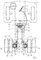
- a lever 2 of a pressurized gas source that can be fitted with pressurized gas cartridges 3 of a commercial type.
- the compressed gas cartridge 3 is opened and compressed gas can flow via the compressed gas line 4 into a compressed gas cylinder 5 with a membrane, not shown, which moves a piston rod 6 in the direction of arrow 7.
- a traverse 8 is connected to the piston rod 6, to which the ends of two pull strands 9 of Bowden cables 10 formed by ropes are fastened, one of which is connected to a swivel unit 11 for the cantilever arm 12 leads one of the two anti-skid devices.
- each boom arm 12 which can be pivoted about an axis 13
- a rotatable holder 14 for a plurality of chain strands 15 is fastened in each case.
- the pull strands 9 press the holders 14 designed as friction wheels against the flanks of the vehicle tires 16 assigned to them as long as the compressed gas cylinder 5 is pressurized with compressed gas.
- the coolers are returned from their operating position to a rest position.
- a pulling cord 17, which is also designed as a rope has an opposite movement into the pivot axis 13 of the extension arm 12, i.e. in the illustrated case, a counterclockwise movement is initiated.
- the tension cord 17 is driven by a return spring which acts on the tension cord via an abutment 19 attached to the end of the tension cord 17.
- the return spring 18 is protected in a cavity 20 of a support member 21.
- Figures 2 to 4 show details of the structure of the swivel unit 11 and the space-saving accommodation of the return spring 18.
- the support member 21 formed by a tube is connected by means of pipe clamps 22 via a holding plate 23 to the wheel axle 24 of the vehicle.
- the housing 25 of the swivel unit in which the swivel axis 13 of the extension arm 12 for the holder 14 is mounted, is captively connected to the support part 21.
- the tension cords 9 and 17 are introduced into the housing 25 of the pivoting unit 11 through openings 26, 27 located opposite one another.
- Both pull strands 9 and 17 enclose at least partially two drive disks 28, 29 arranged one above the other and non-rotatably connected to the pivot axis 13, the end of the pull strand 9 at 30 being connected to the drive disk 28 and the end of the pull strand 17 at 31 being connected to the drive disk 29.
- the apices of the drive disks 28 and 29 formed by eccentrics are arranged offset from one another by approximately 180 ° in such a way that the pull cord 9 in the operating position and the pull cord 17 in the rest position act on the largest possible lever arm on the pivot axis 13.
Landscapes
- Engineering & Computer Science (AREA)
- Automation & Control Theory (AREA)
- Mechanical Engineering (AREA)
- Braking Arrangements (AREA)
- Vehicle Body Suspensions (AREA)
- Pulleys (AREA)
- Regulating Braking Force (AREA)
Claims (7)
- Dispositif anti-dérapant pour véhicules, comprenant plusieurs tronçons de chaînes (15) fixés à un support (14) susceptible d'être déplacé en rotation par un pneu du véhicule, et dont les extrémités opposées au support (14) sont lancées du support (14) lorsqu'il est en rotation, en position de marche, sous l'influence de la force centrifuge, dans la région de la zone de contact au sol du pneu tournant (16) du véhicule, comprenant un entraînement en pivotement (11) disposé sur une pièce porteuse (21) fixée au véhicule et présentant un creux (20), pour un bras (12) portant le support (14), et comprenant des moyens pour communiquer à l'entraînement en pivotement (11) des mouvements de pivotement opposés par lesquels le bras (12) est susceptible d'être déplacé de la position de repos à la position de marche et inversement, caractérisé en ce qu'un premier tronçon de traction (9) susceptible d'être actionné directement ou indirectement par le conducteur du véhicule, et dont une extrémité est fixée à un premier disque d'entraînement (28) relié à l'axe de pivotement (13) de l'entraînement en pivotement (11), sert à communiquer à l'entraînement en pivotement (11) un mouvement de pivotement amenant le bras (12) de la position de repos à la position de marche, et entoure ce disque au moins sur une partie de son pourtour, en ce qu'un deuxième tronçon de traction (17), dont l'extrémité est fixée à un deuxième disque d'entraînement (29) relié à l'axe de pivotement (13) de l'entraînement en pivotement (11), sert, sous l'action d'un ressort de rappel (18), à communiquer à l'entraînement en pivotement (11) un mouvement de pivotement amenant le bras (12) de la position de marche à la position de repos, et entoure ce disque au moins sur une partie de son pourtour, et en ce que le ressort de rappel (18) est disposé dans le creux (20) de la pièce porteuse (21) pour l'entraînement en pivotement (11).
- Dispositif anti-dérapant selon la revendication 1, caractérisé en ce que l'entraînement en pivotement (11) comprend un boîtier (25) solidaire de la pièce porteuse (21), ledit boîtier (25) étant pourvu, sur des côtés opposés, d'ouvertures d'entrée (26, 27) pour les deux tronçons de traction (9, 17).
- Dispositif anti-dérapant selon la revendication 1 ou 2, caractérisé en ce que le ressort de rappel (18) est formé comme un ressort de compression entourant une partie du deuxième tronçon de traction (17) et dont la force est transmise à celui-ci par une butée (19) disposée à l'extrémité du deuxième tronçon de traction (17) opposée au deuxième disque d'entraînement (29).
- Dispositif anti-dérapant selon une ou plusieurs des revendications 1 à 3, caractérisé en ce que les disques d'entraînement (28, 29) sont formés comme des excentriques dont les sommets sont disposés de façon que le premier tronçon de traction (9), dans la position de marche, et le deuxième tronçon de traction (7), dans la position de repos, agissent sur l'axe de pivotement (13) de l'entraînement en pivotement (11) par un bras de levier plus long que dans les autres positions.
- Dispositif anti-dérapant selon la revendication 4, caractérisé en ce que les sommets des disques d'entraînement (28, 29) disposés excentriquement, sont décalés l'un par rapport à l'autre d'environ 180° dans le cas de tronçons d'entraînement (9, 17) introduits du même côté de l'axe de pivotement (13) dans le boîtier (24) de l'entraînement en pivotement (11).
- Dispositif anti-dérapant selon une ou plusieurs des revendications 1 à 5, caractérisé en ce que le premier tronçon de traction (9) est formé comme une partie d'un câble Bowden (10).
- Dispositif anti-dérapant selon une ou plusieurs des revendications 1 à 6, caractérisé en ce que la pièce porteuse (21) est formée d'un tuyau à l'extrémité duquel est disposé l'entraînement en pivotement (11).
Applications Claiming Priority (2)
| Application Number | Priority Date | Filing Date | Title |
|---|---|---|---|
| DE4215371 | 1992-05-08 | ||
| DE4215371A DE4215371A1 (de) | 1992-05-08 | 1992-05-08 | Gleitschutzvorrichtung für Kraftfahrzeuge |
Publications (2)
| Publication Number | Publication Date |
|---|---|
| EP0569111A1 EP0569111A1 (fr) | 1993-11-10 |
| EP0569111B1 true EP0569111B1 (fr) | 1995-08-09 |
Family
ID=6458528
Family Applications (1)
| Application Number | Title | Priority Date | Filing Date |
|---|---|---|---|
| EP93250129A Expired - Lifetime EP0569111B1 (fr) | 1992-05-08 | 1993-05-07 | Dispositif anti-dérapant pour véhicules |
Country Status (4)
| Country | Link |
|---|---|
| US (1) | US5386888A (fr) |
| EP (1) | EP0569111B1 (fr) |
| AT (1) | ATE126137T1 (fr) |
| DE (2) | DE4215371A1 (fr) |
Cited By (1)
| Publication number | Priority date | Publication date | Assignee | Title |
|---|---|---|---|---|
| WO2001058702A1 (fr) | 2000-02-10 | 2001-08-16 | Rud-Kettenfabrik Rieger & Dietz Gmbh U. Co. | Dispositif antiderapant |
Families Citing this family (8)
| Publication number | Priority date | Publication date | Assignee | Title |
|---|---|---|---|---|
| DE19801237A1 (de) * | 1998-01-09 | 1999-07-15 | Rud Ketten Rieger & Dietz | Gleitschutzvorrichtung |
| SE511257C2 (sv) | 1998-01-29 | 1999-09-06 | Vbg Prod Ab | Manöveranordning |
| KR100507138B1 (ko) * | 2001-12-26 | 2005-08-09 | 현대자동차주식회사 | 차량의 스노우체인 구동제어 장치 |
| US7118130B2 (en) * | 2004-01-23 | 2006-10-10 | Onspot Of North America, Inc. | Anti-skid tire chain device |
| US20110146866A1 (en) * | 2009-12-19 | 2011-06-23 | Samad Jafari Valilou | Automatic tire chain system |
| US9731553B2 (en) * | 2012-11-06 | 2017-08-15 | Shane Evan McKenna | Pneumatically-operated rigid linear chain and sprocket actuator for deploying a vehicle snow chain traction system |
| US10675914B2 (en) * | 2017-12-20 | 2020-06-09 | Dusawn Holdings LLC | Tire chains apparatus |
| CN110682732A (zh) * | 2019-09-28 | 2020-01-14 | 徐州顺达钢轮制造有限公司 | 一种防滑的钢轮 |
Family Cites Families (7)
| Publication number | Priority date | Publication date | Assignee | Title |
|---|---|---|---|---|
| AT32851B (de) * | 1906-08-22 | 1908-05-11 | Josef Roesch | Kanaltrockner. |
| US2264466A (en) * | 1940-12-23 | 1941-12-02 | Carleton A Weisel | Antiskid device for vehicles |
| SE8402335D0 (sv) * | 1984-04-27 | 1984-04-27 | Tornebecks Verksteder Kb | Anordning vid slirskydd |
| SE447811B (sv) * | 1985-03-01 | 1986-12-15 | Onspot Ab | Slirskydd |
| DE3611836A1 (de) * | 1986-04-05 | 1987-10-08 | Rud Ketten Rieger & Dietz | Gleitschutzvorrichtung |
| DE3645126C2 (en) * | 1986-07-30 | 1991-01-31 | Rud-Kettenfabrik Rieger & Dietz Gmbh U. Co, 7080 Aalen, De | Fastener for vehicle antiskid unit |
| US5076379A (en) * | 1990-11-19 | 1991-12-31 | Bahr William T | Mechanism for translation of linear motion to rotary motion |
-
1992
- 1992-05-08 DE DE4215371A patent/DE4215371A1/de not_active Withdrawn
-
1993
- 1993-05-06 US US08/058,526 patent/US5386888A/en not_active Expired - Lifetime
- 1993-05-07 DE DE59300447T patent/DE59300447D1/de not_active Expired - Fee Related
- 1993-05-07 AT AT93250129T patent/ATE126137T1/de not_active IP Right Cessation
- 1993-05-07 EP EP93250129A patent/EP0569111B1/fr not_active Expired - Lifetime
Cited By (3)
| Publication number | Priority date | Publication date | Assignee | Title |
|---|---|---|---|---|
| WO2001058702A1 (fr) | 2000-02-10 | 2001-08-16 | Rud-Kettenfabrik Rieger & Dietz Gmbh U. Co. | Dispositif antiderapant |
| DE10006770A1 (de) * | 2000-02-10 | 2001-08-23 | Rud Ketten Rieger & Dietz | Gleitschutzvorrichtung |
| DE10006770C2 (de) * | 2000-02-10 | 2003-10-23 | Rud Ketten Rieger & Dietz | Gleitschutzvorrichtung |
Also Published As
| Publication number | Publication date |
|---|---|
| EP0569111A1 (fr) | 1993-11-10 |
| ATE126137T1 (de) | 1995-08-15 |
| DE4215371A1 (de) | 1993-11-11 |
| DE59300447D1 (de) | 1995-09-14 |
| US5386888A (en) | 1995-02-07 |
Similar Documents
| Publication | Publication Date | Title |
|---|---|---|
| EP1799470B1 (fr) | Console de connecteur pour semi-remorque | |
| EP0191761A1 (fr) | Installation d'utilisation de l'energie de collision d'un vehicule pour tendre une ceinture de securite. | |
| EP0569111B1 (fr) | Dispositif anti-dérapant pour véhicules | |
| DE19734238A1 (de) | Schleppfahrzeug zum Manövrieren von Flugzeugen | |
| EP0110394A2 (fr) | Dispositif d'entraînement pour véhicules et marchandises | |
| DE69510343T2 (de) | Fahrzeug geeignet für strasse und schiene | |
| DE69912396T2 (de) | Schaltvorrichtung | |
| EP1634808A1 (fr) | Véhicule pour remorquer et manoeuvrer des aéronefs | |
| DE60104626T2 (de) | Hilfsantrieb für einen Anhänger | |
| DE2853108C2 (de) | Vorsatzgerät für einen Hublader mit zwei Stelleinrichtungen | |
| DE10113561B4 (de) | Vorschubvorrichtung für eine Ramm- und/oder Bohrvorrichtung | |
| DE102021003926B4 (de) | Kamerahalter und Fahrzeug | |
| DE19528952C2 (de) | Selbstfahrende Vorrichtung zum Innenbefahren von Rohren oder Kanälen | |
| AT409256B (de) | Einrichtung zur notbremsung von transportmitteln | |
| DE2644865A1 (de) | Vorrichtung zum verdrehen eines koerpers, insbesondere der spurstange eines kraftfahrzeugs | |
| EP0241411B1 (fr) | Dispositif antidérapant | |
| DE9206281U1 (de) | Gleitschutzvorrichtung für Kraftfahrzeuge | |
| DE19643371A1 (de) | Selbstfafhrende Vorrichtung zum Innenbefahren von Rohren oder Kanälen | |
| DE3223570C2 (fr) | ||
| DE19649962C2 (de) | Fahrbare Reinigungsmaschine mit Kehreinheit und Scheuereinheit | |
| EP1627846A2 (fr) | Chariot élévateurun avec un champ de vision agrandi | |
| DE4215370C2 (de) | Gleitschutzvorrichtung für Kraftfahrzeuge | |
| DE10006770C2 (de) | Gleitschutzvorrichtung | |
| DE19801237A1 (de) | Gleitschutzvorrichtung | |
| AT407105B (de) | Manuell schaltbare vorrichtung zum sicheren betätigen einer funktionseinheit, wie bremse, kupplung od. dgl. |
Legal Events
| Date | Code | Title | Description |
|---|---|---|---|
| PUAI | Public reference made under article 153(3) epc to a published international application that has entered the european phase |
Free format text: ORIGINAL CODE: 0009012 |
|
| AK | Designated contracting states |
Kind code of ref document: A1 Designated state(s): AT CH DE FR LI SE |
|
| 17P | Request for examination filed |
Effective date: 19931103 |
|
| 17Q | First examination report despatched |
Effective date: 19941013 |
|
| GRAA | (expected) grant |
Free format text: ORIGINAL CODE: 0009210 |
|
| AK | Designated contracting states |
Kind code of ref document: B1 Designated state(s): AT CH DE FR LI SE |
|
| REF | Corresponds to: |
Ref document number: 126137 Country of ref document: AT Date of ref document: 19950815 Kind code of ref document: T |
|
| REF | Corresponds to: |
Ref document number: 59300447 Country of ref document: DE Date of ref document: 19950914 |
|
| ET | Fr: translation filed | ||
| PLBE | No opposition filed within time limit |
Free format text: ORIGINAL CODE: 0009261 |
|
| 26N | No opposition filed | ||
| PGFP | Annual fee paid to national office [announced via postgrant information from national office to epo] |
Ref country code: FR Payment date: 19990517 Year of fee payment: 7 |
|
| PGFP | Annual fee paid to national office [announced via postgrant information from national office to epo] |
Ref country code: CH Payment date: 19990520 Year of fee payment: 7 |
|
| PG25 | Lapsed in a contracting state [announced via postgrant information from national office to epo] |
Ref country code: LI Free format text: LAPSE BECAUSE OF NON-PAYMENT OF DUE FEES Effective date: 20000531 Ref country code: CH Free format text: LAPSE BECAUSE OF NON-PAYMENT OF DUE FEES Effective date: 20000531 |
|
| REG | Reference to a national code |
Ref country code: CH Ref legal event code: PL |
|
| PG25 | Lapsed in a contracting state [announced via postgrant information from national office to epo] |
Ref country code: FR Free format text: LAPSE BECAUSE OF NON-PAYMENT OF DUE FEES Effective date: 20010131 |
|
| REG | Reference to a national code |
Ref country code: FR Ref legal event code: ST |
|
| PGFP | Annual fee paid to national office [announced via postgrant information from national office to epo] |
Ref country code: AT Payment date: 20070521 Year of fee payment: 15 |
|
| PGFP | Annual fee paid to national office [announced via postgrant information from national office to epo] |
Ref country code: SE Payment date: 20070522 Year of fee payment: 15 |
|
| PGFP | Annual fee paid to national office [announced via postgrant information from national office to epo] |
Ref country code: DE Payment date: 20080626 Year of fee payment: 16 |
|
| PG25 | Lapsed in a contracting state [announced via postgrant information from national office to epo] |
Ref country code: AT Free format text: LAPSE BECAUSE OF NON-PAYMENT OF DUE FEES Effective date: 20080507 |
|
| PG25 | Lapsed in a contracting state [announced via postgrant information from national office to epo] |
Ref country code: DE Free format text: LAPSE BECAUSE OF NON-PAYMENT OF DUE FEES Effective date: 20091201 |
|
| PG25 | Lapsed in a contracting state [announced via postgrant information from national office to epo] |
Ref country code: SE Free format text: LAPSE BECAUSE OF NON-PAYMENT OF DUE FEES Effective date: 20080508 |