EP0569208A1 - Lampe à décharge à basse pression - Google Patents
Lampe à décharge à basse pression Download PDFInfo
- Publication number
- EP0569208A1 EP0569208A1 EP93303444A EP93303444A EP0569208A1 EP 0569208 A1 EP0569208 A1 EP 0569208A1 EP 93303444 A EP93303444 A EP 93303444A EP 93303444 A EP93303444 A EP 93303444A EP 0569208 A1 EP0569208 A1 EP 0569208A1
- Authority
- EP
- European Patent Office
- Prior art keywords
- control circuit
- low pressure
- lamp assembly
- discharge lamp
- housing
- Prior art date
- Legal status (The legal status is an assumption and is not a legal conclusion. Google has not performed a legal analysis and makes no representation as to the accuracy of the status listed.)
- Granted
Links
- 239000007858 starting material Substances 0.000 claims abstract description 10
- 230000001154 acute effect Effects 0.000 claims description 2
- QSHDDOUJBYECFT-UHFFFAOYSA-N mercury Chemical compound [Hg] QSHDDOUJBYECFT-UHFFFAOYSA-N 0.000 abstract description 7
- 229910052753 mercury Inorganic materials 0.000 abstract description 7
- 239000011248 coating agent Substances 0.000 description 4
- 238000000576 coating method Methods 0.000 description 4
- PXHVJJICTQNCMI-UHFFFAOYSA-N Nickel Chemical compound [Ni] PXHVJJICTQNCMI-UHFFFAOYSA-N 0.000 description 2
- RYGMFSIKBFXOCR-UHFFFAOYSA-N Copper Chemical compound [Cu] RYGMFSIKBFXOCR-UHFFFAOYSA-N 0.000 description 1
- 229910000831 Steel Inorganic materials 0.000 description 1
- 239000004411 aluminium Substances 0.000 description 1
- XAGFODPZIPBFFR-UHFFFAOYSA-N aluminium Chemical compound [Al] XAGFODPZIPBFFR-UHFFFAOYSA-N 0.000 description 1
- 229910052782 aluminium Inorganic materials 0.000 description 1
- 238000000429 assembly Methods 0.000 description 1
- 230000000712 assembly Effects 0.000 description 1
- 229910052802 copper Inorganic materials 0.000 description 1
- 239000010949 copper Substances 0.000 description 1
- 230000008878 coupling Effects 0.000 description 1
- 238000010168 coupling process Methods 0.000 description 1
- 238000005859 coupling reaction Methods 0.000 description 1
- 230000002708 enhancing effect Effects 0.000 description 1
- 238000004519 manufacturing process Methods 0.000 description 1
- 239000000463 material Substances 0.000 description 1
- 238000005259 measurement Methods 0.000 description 1
- 229910052759 nickel Inorganic materials 0.000 description 1
- 239000004033 plastic Substances 0.000 description 1
- 229920003023 plastic Polymers 0.000 description 1
- 238000002310 reflectometry Methods 0.000 description 1
- 239000007921 spray Substances 0.000 description 1
- 238000004544 sputter deposition Methods 0.000 description 1
- 239000010959 steel Substances 0.000 description 1
- 238000001771 vacuum deposition Methods 0.000 description 1
Images



Classifications
-
- H—ELECTRICITY
- H01—ELECTRIC ELEMENTS
- H01J—ELECTRIC DISCHARGE TUBES OR DISCHARGE LAMPS
- H01J61/00—Gas-discharge or vapour-discharge lamps
- H01J61/02—Details
- H01J61/56—One or more circuit elements structurally associated with the lamp
-
- H—ELECTRICITY
- H01—ELECTRIC ELEMENTS
- H01J—ELECTRIC DISCHARGE TUBES OR DISCHARGE LAMPS
- H01J61/00—Gas-discharge or vapour-discharge lamps
- H01J61/02—Details
- H01J61/30—Vessels; Containers
- H01J61/32—Special longitudinal shape, e.g. for advertising purposes
- H01J61/327—"Compact"-lamps, i.e. lamps having a folded discharge path
Definitions
- This invention relate to a low pressure discharge lamp assembly, and in particular to a low pressure mercury vapour discharge lamp assembly.
- a lamp of this type comprises an H-shaped discharge tube terminating at one end in a connector which can be plugged into a base.
- the connector may contain starter circuitry, and the base usually houses a ballast.
- the base in turn terminates in a bayonet or screw connector for coupling with a light fitting.
- An entire discharge lamp assembly of the type described above is usually too long to fit into a conventional light fitting which has been designed to house an incandescent filament light bulb. As a result, many light fittings need to be changed to accommodate such a low pressure discharge lamp assembly.
- a low pressure discharge lamp assembly comprising a base terminating in a fitting, an elongate control circuit housing being mountable to the base opposite the fitting, and at least a pair of discharge tubes flanking the control circuit housing, the discharge tubes extending away from the base and being splayed away from one another.
- control circuit housing is provided with a reflective outer surface for reflecting light outwardly from the discharge tubes.
- the discharge tubes extend away from the base in a vee-shaped configuration.
- control circuit housing houses both ballast and electronic starter circuitry.
- control circuit housing is detachably mountable to the base via an electromechanical connection, the electromechanical connection including a first set of connectors for connecting the fitting electrically to the control circuit for powering thereof and a second set of connectors for connecting outputs from the control circuit to input leads connected to the discharge tubes.
- control circuit housing includes an electromagnetic and radio frequency interference shield for protecting the control circuit.
- the discharge tubes may be rectilinear.
- the control circuit housing is conveniently wedge-shaped, with the housing tapering outwardly from the base.
- An acute included angle of between 20° and 40°, and preferably 30°, may be defined between the discharge tubes.
- the maximum width of the assembly is advantageously defined by the outermost ends of the discharge tubes, and corresponds to or is less than the maximum width of a conventional incandescent filament light bulb.
- the overall length of the assembly is conveniently reduced by virtue both of the control circuit housing being positioned alongside and between the discharge tubes rather than between the fixed ends of the discharge tubes and the fitting and by the discharge tubes being splayed away from one another.
- a first embodiment of a low pressure mercury vapour discharge lamp assembly 10 comprises a base 12 terminating in a screw connector fitting 14.
- a pair of 7 Watt H-shaped biaxial mercury discharge tubes 16 and 18 of the type manufactured by General Electric extend upwardly from the base in a V-configuration, and are angled from one another at an included angle of approximately 24°, as shown at 20.
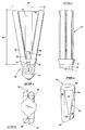
- the discharge tubes 16 and 18 flank a central housing 22 which is wedge-shaped in profile.
- the central housing 22 houses electronic starter circuitry as a well as a choke or ballast.
- the housing 22 has connection pins 24 which allow it to be plugged into a socket arrangement 26 which extends axially from the centre of the base 12.
- the housing preferably has a reflective metallic coating, such as an aluminium coating, applied to its outer surface by vacuum deposition for enhancing its reflectivity.
- the metallic coating doubles as an electromagnetic and radio frequency interference shield for effectively shielding the control circuitry.
- the reflective outer surface may alternatively be constituted by a white plastics material having a gloss finish.
- a further option is to spray a conductive nickel coating onto the outer surface of the housing.
- the housing has a pair of opposed reflective faces 28 and 30, which are arranged to reflect light emitted from the discharge tubes 16 and 18.
- Each face comprises a raised pair of triangular facets 32 and 34 flanked by a flat pair of triangular facets 36 and 38.
- Rectangular side faces 40 and 42 extend between the opposed faces 28 and 30.
- the facets 32 and 34 are angled at approximately 110° from one another in order to provide an even distribution of reflected light from the respective discharge tubes 16 and 18.
- the overall length 44 of the discharge lamp assembly from the top of the screw connector 14 to the end of the discharge tubes 16 and 18 is approximately 102mm.
- the maximum width 46 of the discharge lamp assembly is approximately 55 mm.
- the housing 22 is unplugged from the base and the discharge tubes 16 and 18 and the base 12 to which they are mounted are disposed of The housing 22 is then plugged into a replacement base 12, from which fresh discharge tubes 16 and 18 extend.
- FIG. 6 a second embodiment of a fluorescent lamp assembly 48 is shown which is similar to the embodiment of Figures 1 to 4, with a pair of FW U-shaped tubes 16A and 18A being angled further apart from one another at an included angle of 30°, as is shown at 50.
- the central housing 22A is of substantially the same shape as the central housing 22, save that it has rectangular side faces 40A and 42A which are substantially narrower than the rectangular side faces 40 and 42.
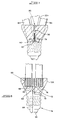
- a printed circuit board, which is indicated in broken outline at 52, is populated with various circuit components 54, including starter circuitry and at last one ballast or choke.
- a ten pin socket 56 is embedded within the base 12A.
- a first pair of leads 57 extends from the lower ends of the first two sockets 58. The leads 57 extend into a cathode terminal 60 of the fluorescent U-tube 16A.
- a similar pair of leads extend from second and third sockets 62 into an anode terminal of the U-tube 16A.
- a positive lead 64 extends from a base contact 66 of the fitting to the lower end of a fifth socket 68, and an earth or negative lead 70 extends from a sixth socket 72 to an outer earth or negative shell 74 of the screw fitting 14.
- the sixth to tenth sockets 76 are provided with corresponding lead which extend into the respective cathode and anode terminals of the U-tube 18A.
- One pair of cathode leads is shown at 78.
- the housing 22A terminates in a corresponding ten pin plug 80 which is arranged to plug into the socket 56.
- FIG. 9 an alternative embodiment of a discharge lamp assembly is shown having a pair of U-tubes 82 and 84 withcorresponding base portions 86 and 88 which extend upwardly from the base 12A in a splayed vee-shaped configuration
- the base portions 86 and 88 terminate in respective upright portions 90 and 92 which are parallel both to one another and to a central axis of symmetry 94.
- a suitably shaped control circuit housing 96 extends between the U-tubes 82 and 84.
- the housing has an upper portion 98 which is square-cylindrical in form, thereby allowing increased space for the various circuitry components such as the starter circuitry and the ballast.
- a conventional incandescent bulb is superimposed in broken outline at 100 onto the embodiment illustrated in Figure 9.
- FIG. 11A a downlight sample test was performed in which a conventional CAS-PROLUX ® 11W-PLE-230V-S lamp assembly 102 was fitted within a cascade downlighter 104. At an average light intensity was measured over a luminous area of 300 cm2 located beneath the downlighter 104. A accompanying polar graph 106 is shown in which average intensity in candelas per kilolumen was measured against degrees. Measurements were taken in the horizontal (0-180°) as well as the vertical (90-270°) planes. The same test was then performed with a fluorescent lamp assembly 48 of the type illustrated in Figure 5, so as to yield a polar graph 108.
- the fluorescent lamp assembly of the invention enjoys a number of advantages over conventional lamp assemblies. Its compact dimensions allow it to be fitted to conventional incandescent light sockets without having to change any light housings. For the same or an even greater light output, it has a power consumption considerably less than that of a conventional incandescent bulb. The bulbs can be replaced without disposing of the starter circuitry, and vice versa.
- the discharge light assembly of the invention makes use of rectilinear fluorescent tubes, which are relatively easy to manufacture in comparison with tubes having more unconventional curved shapes.
Landscapes
- Vessels And Coating Films For Discharge Lamps (AREA)
- Non-Portable Lighting Devices Or Systems Thereof (AREA)
- Circuit Arrangements For Discharge Lamps (AREA)
- Discharge Lamp (AREA)
- Discharge Lamps And Accessories Thereof (AREA)
- Common Detailed Techniques For Electron Tubes Or Discharge Tubes (AREA)
Applications Claiming Priority (2)
| Application Number | Priority Date | Filing Date | Title |
|---|---|---|---|
| ZA923212 | 1992-05-04 | ||
| ZA923212 | 1992-05-04 |
Publications (2)
| Publication Number | Publication Date |
|---|---|
| EP0569208A1 true EP0569208A1 (fr) | 1993-11-10 |
| EP0569208B1 EP0569208B1 (fr) | 1997-01-08 |
Family
ID=25581638
Family Applications (1)
| Application Number | Title | Priority Date | Filing Date |
|---|---|---|---|
| EP93303444A Expired - Lifetime EP0569208B1 (fr) | 1992-05-04 | 1993-05-04 | Lampe à décharge à basse pression |
Country Status (6)
| Country | Link |
|---|---|
| EP (1) | EP0569208B1 (fr) |
| JP (1) | JPH06132016A (fr) |
| AT (1) | ATE147541T1 (fr) |
| CA (1) | CA2095468A1 (fr) |
| DE (1) | DE69307181D1 (fr) |
| ZA (1) | ZA933158B (fr) |
Cited By (4)
| Publication number | Priority date | Publication date | Assignee | Title |
|---|---|---|---|---|
| DE29518894U1 (de) * | 1995-11-30 | 1996-01-25 | Holzer, Walter, Prof. Dr.h.c. Ing., 88709 Meersburg | Kompaktleuchtstofflampe mit Reflektor |
| DE29518752U1 (de) * | 1995-11-29 | 1996-01-25 | Holzer, Walter, Prof. Dr.h.c. Ing., 88709 Meersburg | Gasentladungsgefäß für einseitig gesockelte Leuchtstofflampen |
| DE4439727A1 (de) * | 1994-11-09 | 1996-05-15 | Walter Holzer | Sockel für Kompaktlampen |
| DE19607208A1 (de) * | 1996-02-26 | 1997-08-28 | Holzer Walter Prof Dr H C Ing | Leuchtstofflampe mit auswechselbarem Leuchtteil |
Citations (2)
| Publication number | Priority date | Publication date | Assignee | Title |
|---|---|---|---|---|
| EP0210877A1 (fr) * | 1985-06-27 | 1987-02-04 | Elene S.A. | Lampe à tube fluorescent |
| EP0447957A2 (fr) * | 1990-03-19 | 1991-09-25 | Walter Holzer | Lampe fluorescente compacte |
-
1993
- 1993-05-04 CA CA002095468A patent/CA2095468A1/fr not_active Abandoned
- 1993-05-04 EP EP93303444A patent/EP0569208B1/fr not_active Expired - Lifetime
- 1993-05-04 AT AT93303444T patent/ATE147541T1/de not_active IP Right Cessation
- 1993-05-04 DE DE69307181T patent/DE69307181D1/de not_active Expired - Lifetime
- 1993-05-05 ZA ZA933158A patent/ZA933158B/xx unknown
- 1993-05-06 JP JP5129908A patent/JPH06132016A/ja active Pending
Patent Citations (2)
| Publication number | Priority date | Publication date | Assignee | Title |
|---|---|---|---|---|
| EP0210877A1 (fr) * | 1985-06-27 | 1987-02-04 | Elene S.A. | Lampe à tube fluorescent |
| EP0447957A2 (fr) * | 1990-03-19 | 1991-09-25 | Walter Holzer | Lampe fluorescente compacte |
Cited By (5)
| Publication number | Priority date | Publication date | Assignee | Title |
|---|---|---|---|---|
| DE4439727A1 (de) * | 1994-11-09 | 1996-05-15 | Walter Holzer | Sockel für Kompaktlampen |
| DE29518752U1 (de) * | 1995-11-29 | 1996-01-25 | Holzer, Walter, Prof. Dr.h.c. Ing., 88709 Meersburg | Gasentladungsgefäß für einseitig gesockelte Leuchtstofflampen |
| DE29518894U1 (de) * | 1995-11-30 | 1996-01-25 | Holzer, Walter, Prof. Dr.h.c. Ing., 88709 Meersburg | Kompaktleuchtstofflampe mit Reflektor |
| DE19607208A1 (de) * | 1996-02-26 | 1997-08-28 | Holzer Walter Prof Dr H C Ing | Leuchtstofflampe mit auswechselbarem Leuchtteil |
| DE19607208C2 (de) * | 1996-02-26 | 2002-02-21 | Walter Holzer | Leuchtstofflampe mit auswechselbarem Leuchtteil |
Also Published As
| Publication number | Publication date |
|---|---|
| DE69307181D1 (de) | 1997-02-20 |
| ATE147541T1 (de) | 1997-01-15 |
| EP0569208B1 (fr) | 1997-01-08 |
| CA2095468A1 (fr) | 1993-11-05 |
| JPH06132016A (ja) | 1994-05-13 |
| ZA933158B (en) | 1993-12-07 |
Similar Documents
| Publication | Publication Date | Title |
|---|---|---|
| US4414489A (en) | Compact electric discharge lamp-and-ballast unit, and plug-in ballast module therefor | |
| CA1241991A (fr) | Adaptateur de douille permettant de substituer une lampe a decharge compacte a une lampe a incandescence | |
| US20050184667A1 (en) | CCFL illuminated device and method of use | |
| US6217190B1 (en) | Lighting assembly for multiple fluorescent lamps | |
| KR0129581Y1 (ko) | 컴팩트 형광등의 안정기 구조 | |
| US5320548A (en) | Screw-in adapter for single-based low-pressure discharge lamp, especially compact fluorescent lamp | |
| US7270441B2 (en) | Luminaire with special ballast | |
| US20070070631A1 (en) | [led lamp tube] | |
| EP0281079A2 (fr) | Lampe à décharge à basse pression | |
| US4746835A (en) | Fluorescent lamp device having oval cross sectional tubes | |
| US8256938B2 (en) | Method and system for converting a sodium street lamp to an efficient white light source | |
| EP0569208B1 (fr) | Lampe à décharge à basse pression | |
| JP2000106010A (ja) | 放電ランプ及び照明装置 | |
| US5672932A (en) | Compact lamp assembly with tubular portions arranged in V-shaped configuration | |
| US6107752A (en) | Coaxial applicators for electrodeless high intensity discharge lamps | |
| JP2003036703A (ja) | 照明装置 | |
| US5477439A (en) | Fluorescent lighting system | |
| HK91593A (en) | Adapter for a single-base low-pressure discharge lamp | |
| US6048220A (en) | Lampholder connector for multiple fluorescent lamps | |
| US20050218808A1 (en) | CCFL tube device | |
| EP0860655A3 (fr) | Réflecteur pour lampe à décharge | |
| US6429593B1 (en) | Lighting device | |
| CN1755892B (zh) | 具有可插电极的介质阻挡的放电灯 | |
| WO2010121964A1 (fr) | Unité coupleur-lampe pour lampes à décharge haute intensité sans électrode (ehid) pourvue d'une mémoire et communication de données et d'une traversée commandée en impédance, et système de décharge haute intensité sans électrode pourvu d'une telle unité coupleur-lampe | |
| US20060066245A1 (en) | Illumination system having a dielectric barrier discharge lamp and associated ballast |
Legal Events
| Date | Code | Title | Description |
|---|---|---|---|
| PUAI | Public reference made under article 153(3) epc to a published international application that has entered the european phase |
Free format text: ORIGINAL CODE: 0009012 |
|
| AK | Designated contracting states |
Kind code of ref document: A1 Designated state(s): AT BE CH DE DK ES FR GB GR IE IT LI LU MC NL PT SE |
|
| 17P | Request for examination filed |
Effective date: 19940505 |
|
| 17Q | First examination report despatched |
Effective date: 19950523 |
|
| GRAG | Despatch of communication of intention to grant |
Free format text: ORIGINAL CODE: EPIDOS AGRA |
|
| GRAH | Despatch of communication of intention to grant a patent |
Free format text: ORIGINAL CODE: EPIDOS IGRA |
|
| GRAH | Despatch of communication of intention to grant a patent |
Free format text: ORIGINAL CODE: EPIDOS IGRA |
|
| GRAA | (expected) grant |
Free format text: ORIGINAL CODE: 0009210 |
|
| AK | Designated contracting states |
Kind code of ref document: B1 Designated state(s): AT BE CH DE DK ES FR GB GR IE IT LI LU MC NL PT SE |
|
| PG25 | Lapsed in a contracting state [announced via postgrant information from national office to epo] |
Ref country code: NL Free format text: LAPSE BECAUSE OF FAILURE TO SUBMIT A TRANSLATION OF THE DESCRIPTION OR TO PAY THE FEE WITHIN THE PRESCRIBED TIME-LIMIT Effective date: 19970108 Ref country code: LI Effective date: 19970108 Ref country code: IT Free format text: LAPSE BECAUSE OF FAILURE TO SUBMIT A TRANSLATION OF THE DESCRIPTION OR TO PAY THE FEE WITHIN THE PRE;WARNING: LAPSES OF ITALIAN PATENTS WITH EFFECTIVE DATE BEFORE 2007 MAY HAVE OCCURRED AT ANY TIME BEFORE 2007. THE CORRECT EFFECTIVE DATE MAY BE DIFFERENT FROM THE ONE RECORDED.SCRIBED TIME-LIMIT Effective date: 19970108 Ref country code: GR Free format text: LAPSE BECAUSE OF FAILURE TO SUBMIT A TRANSLATION OF THE DESCRIPTION OR TO PAY THE FEE WITHIN THE PRESCRIBED TIME-LIMIT Effective date: 19970108 Ref country code: FR Effective date: 19970108 Ref country code: ES Free format text: THE PATENT HAS BEEN ANNULLED BY A DECISION OF A NATIONAL AUTHORITY Effective date: 19970108 Ref country code: DK Effective date: 19970108 Ref country code: CH Effective date: 19970108 Ref country code: BE Effective date: 19970108 Ref country code: AT Effective date: 19970108 |
|
| REF | Corresponds to: |
Ref document number: 147541 Country of ref document: AT Date of ref document: 19970115 Kind code of ref document: T |
|
| REG | Reference to a national code |
Ref country code: CH Ref legal event code: EP |
|
| REF | Corresponds to: |
Ref document number: 69307181 Country of ref document: DE Date of ref document: 19970220 |
|
| REG | Reference to a national code |
Ref country code: IE Ref legal event code: FG4D Free format text: 71421 |
|
| PG25 | Lapsed in a contracting state [announced via postgrant information from national office to epo] |
Ref country code: SE Effective date: 19970408 Ref country code: PT Effective date: 19970408 |
|
| PG25 | Lapsed in a contracting state [announced via postgrant information from national office to epo] |
Ref country code: DE Effective date: 19970409 |
|
| PGFP | Annual fee paid to national office [announced via postgrant information from national office to epo] |
Ref country code: GB Payment date: 19970425 Year of fee payment: 5 |
|
| PG25 | Lapsed in a contracting state [announced via postgrant information from national office to epo] |
Ref country code: IE Free format text: LAPSE BECAUSE OF NON-PAYMENT OF DUE FEES Effective date: 19970504 |
|
| PG25 | Lapsed in a contracting state [announced via postgrant information from national office to epo] |
Ref country code: LU Free format text: LAPSE BECAUSE OF NON-PAYMENT OF DUE FEES Effective date: 19970531 |
|
| NLV1 | Nl: lapsed or annulled due to failure to fulfill the requirements of art. 29p and 29m of the patents act | ||
| EN | Fr: translation not filed | ||
| REG | Reference to a national code |
Ref country code: CH Ref legal event code: PL |
|
| PLBE | No opposition filed within time limit |
Free format text: ORIGINAL CODE: 0009261 |
|
| STAA | Information on the status of an ep patent application or granted ep patent |
Free format text: STATUS: NO OPPOSITION FILED WITHIN TIME LIMIT |
|
| PG25 | Lapsed in a contracting state [announced via postgrant information from national office to epo] |
Ref country code: MC Effective date: 19971130 |
|
| 26N | No opposition filed | ||
| PG25 | Lapsed in a contracting state [announced via postgrant information from national office to epo] |
Ref country code: GB Free format text: LAPSE BECAUSE OF NON-PAYMENT OF DUE FEES Effective date: 19980504 |
|
| GBPC | Gb: european patent ceased through non-payment of renewal fee |
Effective date: 19980504 |