EP0569565B1 - A bandage for fixating a cannula of a venous catheter relative toa skin surface part of a person - Google Patents
A bandage for fixating a cannula of a venous catheter relative toa skin surface part of a person Download PDFInfo
- Publication number
- EP0569565B1 EP0569565B1 EP92922362A EP92922362A EP0569565B1 EP 0569565 B1 EP0569565 B1 EP 0569565B1 EP 92922362 A EP92922362 A EP 92922362A EP 92922362 A EP92922362 A EP 92922362A EP 0569565 B1 EP0569565 B1 EP 0569565B1
- Authority
- EP
- European Patent Office
- Prior art keywords
- bandage
- absorbing pad
- bandage according
- support sheet
- glue layer
- Prior art date
- Legal status (The legal status is an assumption and is not a legal conclusion. Google has not performed a legal analysis and makes no representation as to the accuracy of the status listed.)
- Expired - Lifetime
Links
Images

Classifications
-
- A—HUMAN NECESSITIES
- A61—MEDICAL OR VETERINARY SCIENCE; HYGIENE
- A61M—DEVICES FOR INTRODUCING MEDIA INTO, OR ONTO, THE BODY; DEVICES FOR TRANSDUCING BODY MEDIA OR FOR TAKING MEDIA FROM THE BODY; DEVICES FOR PRODUCING OR ENDING SLEEP OR STUPOR
- A61M25/00—Catheters; Hollow probes
- A61M25/01—Introducing, guiding, advancing, emplacing or holding catheters
- A61M25/02—Holding devices, e.g. on the body
-
- A—HUMAN NECESSITIES
- A61—MEDICAL OR VETERINARY SCIENCE; HYGIENE
- A61F—FILTERS IMPLANTABLE INTO BLOOD VESSELS; PROSTHESES; DEVICES PROVIDING PATENCY TO, OR PREVENTING COLLAPSING OF, TUBULAR STRUCTURES OF THE BODY, e.g. STENTS; ORTHOPAEDIC, NURSING OR CONTRACEPTIVE DEVICES; FOMENTATION; TREATMENT OR PROTECTION OF EYES OR EARS; BANDAGES, DRESSINGS OR ABSORBENT PADS; FIRST-AID KITS
- A61F13/00—Bandages or dressings; Absorbent pads
- A61F13/02—Adhesive bandages or dressings
- A61F13/0203—Adhesive bandages or dressings with fluid retention members
- A61F13/0206—Adhesive bandages or dressings with fluid retention members with absorbent fibrous layers, e.g. woven or non-woven absorbent pads or island dressings
-
- A—HUMAN NECESSITIES
- A61—MEDICAL OR VETERINARY SCIENCE; HYGIENE
- A61F—FILTERS IMPLANTABLE INTO BLOOD VESSELS; PROSTHESES; DEVICES PROVIDING PATENCY TO, OR PREVENTING COLLAPSING OF, TUBULAR STRUCTURES OF THE BODY, e.g. STENTS; ORTHOPAEDIC, NURSING OR CONTRACEPTIVE DEVICES; FOMENTATION; TREATMENT OR PROTECTION OF EYES OR EARS; BANDAGES, DRESSINGS OR ABSORBENT PADS; FIRST-AID KITS
- A61F13/00—Bandages or dressings; Absorbent pads
- A61F13/02—Adhesive bandages or dressings
- A61F13/0246—Adhesive bandages or dressings characterised by the skin-adhering layer
- A61F13/025—Adhesive bandages or dressings characterised by the skin-adhering layer having a special distribution arrangement of the adhesive
-
- A—HUMAN NECESSITIES
- A61—MEDICAL OR VETERINARY SCIENCE; HYGIENE
- A61F—FILTERS IMPLANTABLE INTO BLOOD VESSELS; PROSTHESES; DEVICES PROVIDING PATENCY TO, OR PREVENTING COLLAPSING OF, TUBULAR STRUCTURES OF THE BODY, e.g. STENTS; ORTHOPAEDIC, NURSING OR CONTRACEPTIVE DEVICES; FOMENTATION; TREATMENT OR PROTECTION OF EYES OR EARS; BANDAGES, DRESSINGS OR ABSORBENT PADS; FIRST-AID KITS
- A61F13/00—Bandages or dressings; Absorbent pads
- A61F13/02—Adhesive bandages or dressings
- A61F13/0259—Adhesive bandages or dressings characterised by the release liner covering the skin adhering layer
-
- A—HUMAN NECESSITIES
- A61—MEDICAL OR VETERINARY SCIENCE; HYGIENE
- A61F—FILTERS IMPLANTABLE INTO BLOOD VESSELS; PROSTHESES; DEVICES PROVIDING PATENCY TO, OR PREVENTING COLLAPSING OF, TUBULAR STRUCTURES OF THE BODY, e.g. STENTS; ORTHOPAEDIC, NURSING OR CONTRACEPTIVE DEVICES; FOMENTATION; TREATMENT OR PROTECTION OF EYES OR EARS; BANDAGES, DRESSINGS OR ABSORBENT PADS; FIRST-AID KITS
- A61F13/00—Bandages or dressings; Absorbent pads
- A61F2013/00361—Plasters
- A61F2013/00365—Plasters use
- A61F2013/00412—Plasters use for use with needles, tubes or catheters
-
- A—HUMAN NECESSITIES
- A61—MEDICAL OR VETERINARY SCIENCE; HYGIENE
- A61M—DEVICES FOR INTRODUCING MEDIA INTO, OR ONTO, THE BODY; DEVICES FOR TRANSDUCING BODY MEDIA OR FOR TAKING MEDIA FROM THE BODY; DEVICES FOR PRODUCING OR ENDING SLEEP OR STUPOR
- A61M25/00—Catheters; Hollow probes
- A61M25/01—Introducing, guiding, advancing, emplacing or holding catheters
- A61M25/02—Holding devices, e.g. on the body
- A61M2025/0246—Holding devices, e.g. on the body fixed on the skin having a cover for covering the holding means
-
- A—HUMAN NECESSITIES
- A61—MEDICAL OR VETERINARY SCIENCE; HYGIENE
- A61M—DEVICES FOR INTRODUCING MEDIA INTO, OR ONTO, THE BODY; DEVICES FOR TRANSDUCING BODY MEDIA OR FOR TAKING MEDIA FROM THE BODY; DEVICES FOR PRODUCING OR ENDING SLEEP OR STUPOR
- A61M25/00—Catheters; Hollow probes
- A61M25/01—Introducing, guiding, advancing, emplacing or holding catheters
- A61M25/02—Holding devices, e.g. on the body
- A61M2025/0266—Holding devices, e.g. on the body using pads, patches, tapes or the like
-
- A—HUMAN NECESSITIES
- A61—MEDICAL OR VETERINARY SCIENCE; HYGIENE
- A61M—DEVICES FOR INTRODUCING MEDIA INTO, OR ONTO, THE BODY; DEVICES FOR TRANSDUCING BODY MEDIA OR FOR TAKING MEDIA FROM THE BODY; DEVICES FOR PRODUCING OR ENDING SLEEP OR STUPOR
- A61M25/00—Catheters; Hollow probes
- A61M25/01—Introducing, guiding, advancing, emplacing or holding catheters
- A61M25/02—Holding devices, e.g. on the body
- A61M2025/0266—Holding devices, e.g. on the body using pads, patches, tapes or the like
- A61M2025/0273—Holding devices, e.g. on the body using pads, patches, tapes or the like having slits to place the pad around a catheter puncturing site
Definitions
- the present invention relates to a bandage for fixating a cannula of a venous catheter relative to a skin surface part of a person.
- a bandage for fixating a cannula of a venous catheter relative to a skin surface part of a person is known from US Patent No. 4.275.721.
- the known bandage comprises a support sheet of a foil material and of an oblong configuration.
- One side surface of the support sheet is provided with an adhesive layer or a sticky layer, on top of which an absorbing pad is arranged.
- the absorbing pad is located in its entirety within one half of the support sheet, and a rectilinear slit extends from the end or short side of the oblong or rectangularly shaped bandage which end or short side is farthest from the absorbing pad.
- this known bandage constitutes a conventional rectangularly shaped plaster having an offset arranged absorbing pad which is circumferentially enclosed or encircled by the adhesive layer, which rectangularly shaped plaster is further provided with a slit which extends from the short side of the rectangularly shaped plaster farthest from the absorbing pad.
- a conventional plaster may thus easily be converted into this known bandage by simply cutting the conventional plaster into the correct shape so as to locate the absorbing pad in the position offset relative to the centre of the rectangularly shaped bandage and by cutting the slit from the short side of the plaster farthest from the absorbing pad.
- the bandage known from the above-mentioned US Patent for fixating a cannula of a venous catheter relative to a person is by no means of a structure which has been optimized for its intentional application, i.e. for fixating a cannula of a venous catheter relative to a skin surface part of a patient or person.
- this known bandage has to be used in connection with a supporting pad which has to be inserted between the skin surface part of the patient or person and the cannula of the venous catheter, which cannula is to be fixated by means of the bandage.
- the supporting pad clearly makes it complicated to fixate the cannnula relative to the skin surface part by means of the bandage as not only the cannula has to be kept in a specific position while applying the bandage, but also the supporting pad has to be kept in a desired position supporting the cannula. It has further been realized that this rectangularly shaped, plaster-like bandage known from the above-mentioned US Patent suffers from inherent drawbacks originating from the fact that the overall structure is merely a conventional plaster.
- the structure has not been adapted to on the one hand handling the bandage while applying the bandage to the skin surface part of the patient or person for fixating the cannula of a venous catheter and also the supporting pad, if any, and on the other hand, fixating and maintaining the cannula of the venous catheter in a fixed position in order to eliminate any risk of moving the cannula of the venous catheter relative to the supporting skin surface part of the patient or person, which movement might cause damage to the vein of the patient or person, which vein has received the cannula of the venous catheter, or cause other severe damage due to perforation of tissue of the patient or person.
- An object of the present invention is to provide a bandage for fixating a cannula of a venous catheter relative to a skin surface part of a person, which bandage is optimized as to on the one hand the handling of the bandage and the cannula while applying the bandage to the cannula and the skin surface part of the person, to which skin surface part the cannula is to be fixated, and on the other hand the fixation of the cannula relative to the person's skin surface part for providing a reliable fixation of the cannula relative to the skin surface part in order to eliminate any risk of causing injuries or harm to the person as a result of unintentional shifting or movement of the cannula relative to the skin surface part.
- a particular advantage of the present invention originates from the fact that the bandage according to the present invention may be used without a supporting pad on which the cannula has to rest or has to be supported.
- a particular feature of the bandage according to the present invention relates to a highly advantageous absorbing capability due to an enlarged absorbing pad as compared to the above described conventional plaster-like bandage.
- a bandage for fixating a cannula of a venous catheter relative to a skin surface part of a person which bandage in accordance with the teaching of the present invention comprises: a support sheet of a foil material having opposite first and second side surfaces and defining an outer rim, an adhesive layer applied to and covering the first side surface, an absorbing pad arranged at and adhering to the first side surface, the absorbing pad being located at a distance from the outer rim and being circumferentially encircled by the adhesive layer, characterized in said absorbing pad further being divided into first and second parts, the first part being contiguous to the adhesive layer, a glue layer applied to the first side surface and covering the first part of the absorbing pad, the second part of the absorbing pad being uncovered by the glue layer, and a slit cut through the supporting sheet and extending from the outer rim through the adhesive layer and into
- the term adhesive layer is meant to describe a layer of an adhesive generating a coefficient of adhesion to a stainless steel surface (A.F.E.R.A.: "Association des Fabricants Eurofugs de Rubans Auto-Adhesifs", Test, ref. 4001) less than 1.97 N/cm (5 N/inch), e.g. of the order of 1.54 - 1.97 n/cm (4-5 N/inch), i.e. a fairly weak bond to the skin surface part of the type well-known from conventional plasters.
- a glue layer is meant to describe a layer of glue generating a coefficient of adhesion to a stainlss steel surface (A.F.E.R.A.: "Association des Fabricants Eurofugs de Rubans Auto-Adhesifs", Test, ref. 4001) of the order of 2.36 - 3.94 N/cm (6-10 N/inch), e.g. of the order of 2.75 - 3.15 N/cm (7-8 N/inch), i.e. an adhesion or a bond stronger than the bond obtained by means of an adhesive layer.
- A.F.E.R.A.: "Association des Fabricants Eurofugs de Rubans Auto-Adhesifs", Test, ref. 4001 of the order of 2.36 - 3.94 N/cm (6-10 N/inch), e.g. of the order of 2.75 - 3.15 N/cm (7-8 N/inch), i.e. an adhesion or a bond stronger than the bond obtained by means of an adhesive layer.
- the absorbing pad is divided into two parts, namely a first part covered by the glue layer and generating an absorbing reservoir inserted between the covering glue layer and the support sheet, and an uncovered or exposed part which is to be arranged covering the point of the skin surface part through which point the cannula is inserted into the vein and perforates the tissue.
- the provision of the glue layer in accordance with the teaching of the present invention firstly establishes a strong bond between the bandage and the supporting skin surface part and consequently an extremely reliable fixation of the bandage relative to the skin surface part.
- the glue layer brings about a strong bond between the support sheet of the bandage and the cannula of the venous catheter and consequently establishes an extremely reliable fixation of the cannula of the venous catheter relative to the skin surface part.
- the first part of the pad which part is provided with or covered with the glue layer, establishes the bond between the support sheet and the cannula and further between the support sheet and the skin surface part and establishes a water- and bacteria-tight barrier across the cannula of the venous catheter.
- the foil material of the support sheet of the bandage according to the present invention may be made from any appropriate material which may be used as a supporting sheet material.
- the adhesive layer and the glue layer are substantially water-impermeable, the foil material may be made from water-impermeable or water-permeable material.
- the foil material is, however, preferably a substantially water-impermeable material.
- the bandage may be of any appropriate configuration, such as a polygonal, circular or triangular configuration, however, preferably being of a rectangular configuration.
- the support sheet, and consequently the overall bandage is of a quadratic configuration.
- the absorbing pad of the bandage according to the present invention may be located at any appropriate location at a distance from the outer rim of the support sheet and circumferentially encircled by the adhesive layer.
- the absorbing pad of the bandage according to the present invention may be located centrally at the first side surface of the support sheet or alternatively located offset relative to a central position of the first side surface of the support sheet.
- the absorbing pad of the bandage may be of any appropriate configuration, such as a polygonal, circular, triangular, or preferably a rectangular or quadratic configuration.
- the glue layer characteristic of the present invention preferably additionally covers a part of the adhesive layer adjacent to the first part of the absorbing pad.
- the glue layer is advantageously perforated.
- the glue layer of the bandage according to the present invention may cover a minor area of the first side surface of the support sheet which area may be located at a distance from the outer rim of the support sheet.
- the glue layer constitutes a glue layer strip extending across the first side surface of the support sheet which further increases the bond between the support sheet and the skin surface part and consequently the overall fixation of the bandage and the cannula as well.
- the bandage preferably further comprises a release foil.
- the release foil of the bandage according to the present invention is preferably divided into two or more separate sections having individual gripping tabs adjoining one another, e.g. at the absorbing pad or preferably at said first part of said absorbing pad.
- the two or more separate sections of the release foil having individual gripping tabs may adjoin one another along a line crossing the slit.
- the two or more individual sections of the release foil should preferably adjoin one another at a position shifted away from the centre of the absorbing pad contrary to the structure known from the above-mentioned US patent, as the shifting of the position at which the individual sections of the release foil adjoin one another from the centre of the absorbing pad renders it far more easy to position the absorbing pad correctly relatively to the cannula of the venous catheter, or more precisely relative to the point at which the cannula is introduced into the vein of the person through the skin surface part of the person and to fixate the bandage relative to the skin surface part by removing the release foil.
- the slit constitutes a straight line
- the line along which the two or more separate sections of the release foil adjoin one another is preferably perpendicular to the slit constituting a straight line or a rectilinear slit.
- the rectilinear slit preferably extends from a short or long side of the rim of the rectangular or quadratic support sheet, and preferably perpendicular to the rim of the rectangular support sheet.
- a first embodiment of a bandage for fixating a cannula of a venous catheter relative to a skin surface part of a person is shown designated the reference numeral 10 in its entirety.
- the skin surface part may e.g. constitute a skin surface part at the back of the person's hand or a skin surface part on the back, forearm, chest or one of the legs of the person in question.
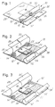
- the bandage 10 basically comprises a support sheet 12 of a foil material, such as a plastic material, a woven or non-woven fibrous material or any other appropriate foil material and of a substantially quadratic configuration.
- the sheet 12 is at its one side surface constituting a first side surface to be arranged in contact with and fixated relative to the skin surface part of the person in question, provided with an adhesive layer 14 covering the entire first side surface of the support sheet.
- an absorbing pad 16 is arranged on top of the adhesive layer 14, and adhering thereto.
- the absorbing pad 16 is made from a fibrous material which is an organic-compatible material.
- the absorbing pad 16 is, as is evident from Figs. 1 and 2, arranged centrally relative to the first side surface of the substantially quadratic support sheet 12.
- a glue layer 18 extends from one side of the substantially quadratic support sheet 12 to the opposite side of the substantially quadratic support sheet 12.
- the glue layer 18 may be constituted by a glue layer applied to the support sheet, e.g. by means of an applicator or a spray nozzle, or may comprise an adhesive tape including a carrier foil such as a woven or non-woven fibre material foil impregnated on both sides with a glue or adhesive and differs from the adhesive layer 14 in that the glue of the glue layer 18 provides a far stronger adhesion to the tissue or any other material as compared to the adhesion of the adhesive layer 14.
- the glue layer 18 serves the basic purposes of providing a stronger bond to the tissue of the skin surface part of the person, to which skin surface part the bandage 10 is applied so as to provide a stronger and more reliable and lasting fixation of the bandage as compared to a bandage of conventional structure, which conventional bandage is not provided with a glue layer similar to the glue layer 18 and of fixating the cannula of the venous catheter relative to the skin surface part of the person, as will be evident from the description below.
- the absorbing pad 16 is divided into two parts designated the reference numerals 22 and 24, respectively, which parts constitute a part uncovered by the glue layer 18 and a part covered by the glue layer 18, respectively.
- the glue layer 18 serves the additional or supplementary purpose of providing a strong and reliable fixation of the absorbing pad relative to the skin surface part of the person to which the bandage 10 is applied in order to eliminate any risk that the absorbing pad 16 during the application of the bandage or after the bandage has been applied to the skin surface, is shifted from a specific position relative to a perforated point of the skin surface part at which the uncovered part 22 of the absorbing pad 16 is arranged.
- a slit 20 is provided, which slit extends from a side of the substantially quadratic support sheet 12 perpendicular to the glue layer 18 and through the glue layer 18 and into the absorbing pad 16.
- the adhesive layer 14, the uncovered part 22 of the absorbing pad 16, and the glue layer 18 are covered by a total of three sheets of a release foil designated the reference numeral 26, 32, and 36.
- the sheet 26 constitutes a major sheet which covers the major surface part of the first side surface of the support sheet and extends from a side of the substantially quadratic support sheet 12, which side is opposite to the side from which the slit 20 extends into the glue layer 18, and covers not only the major part of the adhesive layer 14, the uncovered part 22 of the absorbing pad 16, but also approximately one half of the glue layer 18.
- the slit 20 also divides or partly separates the sheet 26 and divides a gripping tab of the sheet 26 into two separate gripping tabs 28 and 30.
- the two remaining release foil sheets 32 and 36 have gripping tabs, designated the reference numerals 34 and 38, respectively.
- the sheets 26 and 32,36 meet one another along a line extending along the glue layer 18 approximately at the central line of the glue layer 18, as is evident from Fig. 1.
- the provision of a total of three release foil sheets meeting one another along a line extending along the glue layer 18 provides a highly advantageous feature as to the application of the bandage 10, as will be discussed below with reference to Figs. 4 and 5.
- the release foil sheets 26, 32, and 36 are shown arranged in contact with and covering the adhesive layer 14, the glue layer 18, and the absorbing pad 16, whereas in Fig. 2, the release foil sheets 26, 32, and 36 are partly removed from the bandage 10 disclosing the adhesive layer 14, the glue layer 18, and further the absorbing pad 16, i.e. the adhering, wound-covering and absorbing parts of the bandage to be applied or arranged in contact with the skin surface part of the person in question to which skin surface part a cannula of a venous catheter is to be fixated.
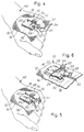
- a hand 40 of a person or a patient is shown. More precisely, the back of the hand is shown, to which a cannula assembly 50 is applied or arranged.
- the cannula assembly 50 is basically of a conventional structure and comprises an assembly body 52 from which a needle extends, which needle is shown in phantom lines in Fig. 5 and designated the reference numeral 58.
- the assembly body 52 further receives two plugs 54 and 56, which plug 54 serves the purpose of blocking an opening of the assembly body 52 and of allowing the administration or introduction of a medicament or a drug to the person or patient.
- the plug 54 serves the purpose of blocking an opening of the assembly body 52, to which opening the venous catheter is to be connected.
- the cannula assembly 50 further comprises two wing components, one of which is shown in phantom lines in Fig. 6 and designated the reference numeral 60.
- the wings such as the wing 60, serve the purpose of preventing the cannula assembly 50 from tilting as the cannula assembly is arranged in contact with the skin surface of the back of the person's hand after the needle 58 has been introduced into the vein at the back of the person's hand.
- the bandage 10 is applied on top of the cannula assembly 50, as is illustrated in Fig. 4, in order to firstly cover the point of the skin surface part of the person, through which point the needle 58 is introduced into the vein and perforates the tissue, secondly of fixating the cannula assembly 50 relative to the back of the person's hand, and thirdly of sealing said point through which the needle is introduced into the vein in order to exclude bacteria from the environment from getting into the vein and causing infections.
- the bandage 10 is preferably applied in the following way.
- the part 22 of the absorbing pad 16 is arranged above the point of the person's skin surface, through which point the needle 58 perforates the tissue, and the entire bandage 10 is arranged in a position, so to speak straddling the cannula assembly 50.
- the release foil sheet 26 is now removed by gripping one of the gripping tabs 28 and 30 and by pulling off the release foil sheet 26, while still maintaining the uncovered or exposed part 22 of the absorbing pad 16 in the intentional correct position.
- the needle 58 and the body 52 of the cannula assembly 50 is now partly fixated by pressing the uncovered part of the glue layer 18 into contact with the needle 58 and the body 52 of the cannula assembly 50 and further into intimate contact with the outer side surface of the person for fixating the bandage 10 relative to the person's skin.
- the release foil sheets 32 and 36 are removed one at a time, which renders it possible to fixate the wings of the body 52 of the cannula assembly 50 properly and correctly by simply tearing off the release foil sheet and pressing down the bandage against the back of the person's hand.
- Fig. 4 the stage of eventually removing the release foil sheet 32 is disclosed, whereas in Fig. 5, the entire bandage 10 is correctly applied and fixated for fixating the cannula assembly 50.
- Fig. 6 an enlarged, partly broken away view is shown illustrating the cannula assembly 50 and the adjacent parts of the bandage 10. It is to be emphasized that contrary to conventional bandages of this type, the bandage according to the present invention, as is evident from Fig.
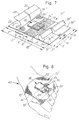
- FIGs. 3 and 7 second and third embodiments, respectively, of the bandage according to the present invention are shown, which embodiments are basically of a structure similar to the structure of the first embodiment of the bandage according to the present invention described above with reference to Figs. 1 and 2.
- the second embodiment shown in Fig. 3 basically differs from the above described first embodiment in that the bandage is of a somewhat different geometrical configuration as the support sheet is of a rectangular configuration.
- the second embodiment shown in Fig. 3 is identical to the first embodiment discussed above with reference to Figs. 1 and 2.
- FIG. 3 is in its entirety designated the reference numeral 10', and components or parts of the second embodiment 10' of the bandage according to the present invention, which components or parts differ from similar components of the first embodiment 10 of the bandage according to the present invention described above with reference to Figs. 1 and 2 in the geometrical shape or dimensions exclusively are designated the same reference numerals as the corresponding component or part of the first embodiment 10, however, supplemented with a '.
- the support sheet of the second embodiment 10' shown in Fig. 3 which support sheet corresponds to the support sheet 12 shown in Figs. 1 and 2, is designated the reference numeral 12'.
- the components or parts 14', 18', 26', 28', 30', 32', 34', 36', and 38' of the second embodiment 10' of the bandage according to the present invention correspond to the components 14, 18, 26, 28, 30, 32, 34, 36, and 38, respectively, shown in Figs. 1 and 2 and discussed above with reference thereto.
- the second embodiment 10' of the bandage according to the present invention is shown applied to the hand 40 of the person or patient to which the cannula assembly 50 is applied.
- the increased width of the second embodiment 10' as compared to the substantially quadratic first embodiment 10 shown in Figs. 4 and 5 is evident.
- a third embodiment of the bandage according to the present invention is shown, which bandage is designated the reference numeral 10''.
- components or parts of the third embodiment 10'' of the bandage according to the present invention which components or parts correspond to components or parts of the first embodiment 10 of the bandage according to the present invention described above with reference to Figs. 1 and 2 are designated the same numerals, however, added a ''.
- the third embodiment of the bandage 10'' shown in Fig. 7 differs from the first embodiment 10 shown in Figs. 1 and 2 in that the support sheet 12 is of a rectangular configuration.
- the absorbing pad 22 is arranged centrally relative to the support sheet 12' and the slit 20 extends from one of the long sides of the rectangularly shaped support sheets 12'
- the absorbing pad 16 of the third embodiment 10'' of the bandage according to the present invention shown in Fig. 7 is arranged offset relative to the centre of the support sheet 12''.
- the second embodiment 10'' constitutes an elongated structure as the slit 20 extends from one of the short sides of the rectangularly shaped support sheet 12'' which short side constitutes the short side relative to which the absorbing pad 16 is arranged at the longest distance.
- the glue layer 18'' is a perforated glue layer, as a number of holes 19 extending through the glue layer are provided.
- the perforation of the glue layer 18'' serves the purpose of rendering the second part 24'' of the absorbing pad 16 at least partially absorbing, so that the second part 24'' of the absorbing pad 16 may absorb liquid, such as blood, as the bandage 10'' is arranged on the back of a person's hand, as disclosed in Figs. 4, 5, and 8.
- the dimensions of the support sheet 12'' are indicated as the length l and the width w.
- the spacing or distances between the different components or parts of the bandage 10'' are designated references a, b, c, d, e, f, g, and h. These dimensions or distances are also applicable to the first embodiment 10 shown in Figs. 1 and 2, and the second embodiment 10' shown in Fig. 3.
- a dotted line 21 is further shown, which dotted line may be marked on the release foil sheets 32'' and 36'' and indicating a cutting line along which the bandage 10'' may be cut, e.g. by means of scissors, so as to convert the elongated, rectangularly shaped bandage 10'' into a quadratic bandage in which the absorbing pad 16 is arranged centrally relative to the support sheet 12''. Consequently, by reducing the length l of the entire bandage 10'' to the dimension w, the third embodiment 10'' shown in Fig 7 is modified into a bandage similar to the first embodiment 10 shown in Figs. 1 and 2, however, differing from the first embodiment 10 in that the glue layer 18'' is perforated.
- a fourth embodiment of the bandage according to the present invention is shown, which embodiment is basically of a structure similar to the structure of the first embodiment of the bandage according to the present invention described above with reference to Figs. 1 and 2.
- Fig. 9 discloses a side surface of the fourth embodiment of the bandage opposite to the side surface of the first, second, and third embodiments shown in Figs. 1 and 2, 3, and 7, i.e. a second side surface opposite to the first side surface to be arranged in contact with the skin surface part of the patient or person and consequently facing outwards.
- the fourth embodiment of the bandage according to the present invention shown in Fig. 9 is in its entirety designated the reference numeral 10''', and components or parts of the fourth embodiment 10''' of the bandage according to the present invention, which components or parts differ from similar components of the first embodiment 10 of the bandage according to the present invention described above with reference to Figs. 1 and 2 in the geometrical shape or dimensions exclusively, are designated the same reference numerals as the corresponding component or part of the first embodiment 10, however, supplemented with a '''.
- the components or parts 12''', 14''', and 18''' of the fourth embodiment 10''' of the bandage according to the present invention correspond to the components 12, 14, and 18, respectively, shown in Figs. 1 and 2 and discussed above with reference thereto.
- a non-rectilinear slit designated the reference numeral 25 is shown in Fig. 9, which slit serves the purpose of providing a tab 23 of the support foil 12, which tab may serve the purpose of fixating a tubing of the venous catheter as will be described below with reference to Fig. 10.
- the release foils 32 and 36 are combined into a single release foil having a single gripping tab 33.
- the release foil 26 is similarly enlarged and provided with a gripping tab 31, which gripping tab 31 meets the gripping tab 33 along a rectilinear segment of the slit 25, which rectilinear segment extends parallel with the glue layer 18'''.
- the reference numeral 25' designates an alternative configuration of the non-rectilinear slit 25.
- the fourth embodiment 10''' of the bandage according to the present invention is shown applied to the back of the hand 40 of the patient or person to which the cannula assembly 50 is applied.
- the cannula assembly 50 is further provided with a tubing 57 which is fixed to the plug 56 and further fixated relative to the back of the hand 40 by means of the tab 23 of the support foil 12''' of the fourth embodiment 10''', which tab 23 is applied across the tubing 57.
- the support sheet 12'' was made from a non-woven 100% polyester foil of the type CHICOPEE (TM), Keyback Style of a density of approx. 62 g/m 2 and of a thickness of approx. 300 ⁇ m.
- the length l and width w of the support sheet 12'' was 72 mm and 72 mm, respectively.
- the adhesive layer 14'' was a medical acrylic adhesive
- the glue layer 18'' was a synthetic rubber resin adhesive applied to both sides of a carrier strip of low density, non-woven polyester foil.
- the perforation holes 19 were constituted by cuts or slits of a length of approx. 2 mm.
- the absorbing pad 16 measured (b + c) x g: 28 mm x 21 mm and was made from 100% cotton fibres.
- the release foil from which the sheets 26, 32, and 36 were made was a siliconized paper foil of a density of approx. 100 g/m 2 and a thickness of approx. 100 ⁇ m.
- the width d of the glue layer 18 was 20 mm, the dimension b was 12 mm, and the dimension c was 16 mm.
- the distance a was 22 mm, and the dimension e was 18 mm.
- the dimensions f and h were both 36 mm.
- the length and the width of the support sheet 12 or 12' may be of the order 80 mm x 70 mm, 75 mm x 70 mm, 80 mm x 75 mm, 95 mm x 70 mm.
- the dimension a is preferably of the order of 20-25 mm
- the ratio b/c is preferably equal to or less than 1
- the distance e is preferably of the order of 15-30 mm
- the ratio (b + c)/g is preferably larger than 1, however, less than 2.
- the dimensions f and h are preferably identical.
- the support sheet may be made from spun bond, spun lace, woven or non-woven foil materials of polyester, nylon, polypropylene, polyethylene, polyurethane, polyvinylchloride, clear tape or other transparent or non-transparent material, or combinations thereof, e.g. providing a separate transparent area adjacent to the absorbing pad through which transparent area the tip of the needle of the venous catheter may be viewed or disclosed.
- the support sheet is made from a foil material of a thickness of 150-400 ⁇ m.
- the adhesive layer may be constituted by a medical, natural or synthetic rubber resin adhesive or other medical grade adhesive.
- the release foil may be constituted by a siliconized or non-siliconized polyester, polypropylene, polyethylene or similar plastic material. Preferably, the release foil is of a thickness of 70-150 ⁇ m.
- the absorbing pad may be made from cross-laid, fibre-bonded viscose-rayon or polyester material, including polyolefine and similar absorbent fibre material.
- the glue layer may be made from e.g. a polyester tape provided with a medical acrylic adhesive or medical synthetic rubber resin on both sides. Alternatively, any strong bond medical grade adhesive may be used, providing a glue layer supported by a carrier of woven or non-woven fibre material, such as polyester fibre material or the like.
Landscapes
- Health & Medical Sciences (AREA)
- Life Sciences & Earth Sciences (AREA)
- General Health & Medical Sciences (AREA)
- Public Health (AREA)
- Heart & Thoracic Surgery (AREA)
- Veterinary Medicine (AREA)
- Engineering & Computer Science (AREA)
- Animal Behavior & Ethology (AREA)
- Biomedical Technology (AREA)
- Vascular Medicine (AREA)
- Dermatology (AREA)
- Biophysics (AREA)
- Pulmonology (AREA)
- Anesthesiology (AREA)
- Hematology (AREA)
- Materials For Medical Uses (AREA)
- Media Introduction/Drainage Providing Device (AREA)
Applications Claiming Priority (3)
| Application Number | Priority Date | Filing Date | Title |
|---|---|---|---|
| DK911939A DK193991D0 (da) | 1991-11-29 | 1991-11-29 | A bandage for fixating a cannula of a venous catheter relative to a skin surface part of a person |
| DK1939/91 | 1991-11-29 | ||
| PCT/DK1992/000289 WO1993000788A2 (en) | 1991-11-29 | 1992-10-01 | A bandage for fixating a cannula of a venous catheter relative toa skin surface part of a person |
Publications (2)
| Publication Number | Publication Date |
|---|---|
| EP0569565A1 EP0569565A1 (en) | 1993-11-18 |
| EP0569565B1 true EP0569565B1 (en) | 1996-08-14 |
Family
ID=8109051
Family Applications (1)
| Application Number | Title | Priority Date | Filing Date |
|---|---|---|---|
| EP92922362A Expired - Lifetime EP0569565B1 (en) | 1991-11-29 | 1992-10-01 | A bandage for fixating a cannula of a venous catheter relative toa skin surface part of a person |
Country Status (6)
| Country | Link |
|---|---|
| EP (1) | EP0569565B1 (da) |
| AT (1) | ATE141174T1 (da) |
| AU (1) | AU2803292A (da) |
| DE (1) | DE69212809T2 (da) |
| DK (1) | DK193991D0 (da) |
| WO (1) | WO1993000788A2 (da) |
Cited By (4)
| Publication number | Priority date | Publication date | Assignee | Title |
|---|---|---|---|---|
| CN102802715A (zh) * | 2010-02-09 | 2012-11-28 | 艾利丹尼森公司 | 具有无粘合剂特征的多个可移除带的卫生保健结构组件 |
| US8663171B2 (en) | 2006-05-12 | 2014-03-04 | Fresenius Medical Care Deutshland Gmbh | Medical-use bandage |
| WO2025003255A1 (en) * | 2023-06-28 | 2025-01-02 | Cardiobotics Sp. Z O.O. | Adhesive patch for application at an injury site of a patient and method for monitoring fluid bleeding using the same adhesive patch |
| WO2025003251A1 (en) * | 2023-06-28 | 2025-01-02 | Cardiobotics Sp. Z O.O. | Adhesive patch for application at an injury site of a patient and method for monitoring fluid bleeding using the same adhesive patch |
Families Citing this family (16)
| Publication number | Priority date | Publication date | Assignee | Title |
|---|---|---|---|---|
| GB9307312D0 (en) * | 1993-04-07 | 1993-06-02 | United Surgical Services Ltd | Surgical wound dressings |
| DE19512013C1 (de) * | 1995-03-31 | 1996-05-02 | Beiersdorf Ag | Selbstklebende Fertigbandage für Ellenbogen |
| DE19517209C2 (de) * | 1995-05-11 | 1997-03-06 | Beiersdorf Ag | Selbstklebende Fertigbandage für die Patella |
| EP1011780A1 (en) * | 1996-09-10 | 2000-06-28 | Maersk Medical A/S | A bandage for fixating a cannula of a venous catheter to a skin surface part of a person |
| US6267115B1 (en) * | 2000-09-25 | 2001-07-31 | Florine Marshel | Intravenous protecting device |
| GB2367245B (en) * | 2000-09-29 | 2004-11-17 | Johnson & Johnson Medical Ltd | Adaptable dressings |
| WO2004026389A2 (en) * | 2002-09-20 | 2004-04-01 | Becton Dickinson And Company | Dressing for catheter assembly |
| DE20219118U1 (de) | 2002-12-10 | 2003-02-27 | Lohmann & Rauscher GmbH & Co. KG, 56567 Neuwied | Fixierpflaster |
| GB0308311D0 (en) | 2003-04-10 | 2003-05-14 | Bristol Myers Squibb Co | Wound dressing |
| ES2237348B1 (es) * | 2005-03-16 | 2006-05-16 | Jose Sabater Robles | Dispositivo de fijacion de canulas y similares a una parte del cuerpo humano. |
| EP2468228A1 (en) | 2010-12-23 | 2012-06-27 | Region Midtjylland | Cover unit for use when inserting a puncture device in an anatomical structure such as a vein or an artery and for maintaining said puncture device in the anatomical structure |
| DE202012009233U1 (de) * | 2012-09-25 | 2013-01-08 | Michael Zachmann | Antibakteriellbehandelte Schutzvorlage speziell für Kathederpatienten M/W |
| WO2014058828A2 (en) * | 2012-10-09 | 2014-04-17 | Lakeshore Medical Innovations, Llc | Method and device for interventional site management of sheaths and catheters |
| EP2909270A1 (en) | 2012-10-22 | 2015-08-26 | Avery Dennison Corporation | Hybrid material of crosslinked microgel particles dispersed in an adhesive |
| JP6130130B2 (ja) * | 2012-12-04 | 2017-05-17 | シスメックス株式会社 | 体液収集具 |
| US9629983B2 (en) | 2013-03-08 | 2017-04-25 | Ethicon, Inc. | All in one antimicrobial dressing for catheter coverage |
Family Cites Families (5)
| Publication number | Priority date | Publication date | Assignee | Title |
|---|---|---|---|---|
| SE419163B (sv) * | 1978-09-11 | 1981-07-20 | Harry Karlsson | Plaster avsett att fasthalla en kanyl |
| SE414994B (sv) * | 1978-11-28 | 1980-09-01 | Landstingens Inkopscentral | Venkateterforband |
| EP0168174A1 (en) * | 1984-06-13 | 1986-01-15 | Smith & Nephew Inc. | Film dressing |
| SE455268B (sv) * | 1986-05-23 | 1988-07-04 | Moelnlycke Ab | Kanylfesttejp |
| GB8706116D0 (en) * | 1987-03-14 | 1987-04-15 | Smith & Nephew Ass | Adhesive dressings |
-
1991
- 1991-11-29 DK DK911939A patent/DK193991D0/da unknown
-
1992
- 1992-10-01 WO PCT/DK1992/000289 patent/WO1993000788A2/en not_active Ceased
- 1992-10-01 AU AU28032/92A patent/AU2803292A/en not_active Abandoned
- 1992-10-01 AT AT92922362T patent/ATE141174T1/de active
- 1992-10-01 EP EP92922362A patent/EP0569565B1/en not_active Expired - Lifetime
- 1992-10-01 DE DE69212809T patent/DE69212809T2/de not_active Expired - Lifetime
Cited By (5)
| Publication number | Priority date | Publication date | Assignee | Title |
|---|---|---|---|---|
| US8663171B2 (en) | 2006-05-12 | 2014-03-04 | Fresenius Medical Care Deutshland Gmbh | Medical-use bandage |
| CN102802715A (zh) * | 2010-02-09 | 2012-11-28 | 艾利丹尼森公司 | 具有无粘合剂特征的多个可移除带的卫生保健结构组件 |
| CN102802715B (zh) * | 2010-02-09 | 2015-02-18 | 艾利丹尼森公司 | 具有无粘合剂特征的多个可移除带的卫生保健结构组件 |
| WO2025003255A1 (en) * | 2023-06-28 | 2025-01-02 | Cardiobotics Sp. Z O.O. | Adhesive patch for application at an injury site of a patient and method for monitoring fluid bleeding using the same adhesive patch |
| WO2025003251A1 (en) * | 2023-06-28 | 2025-01-02 | Cardiobotics Sp. Z O.O. | Adhesive patch for application at an injury site of a patient and method for monitoring fluid bleeding using the same adhesive patch |
Also Published As
| Publication number | Publication date |
|---|---|
| DE69212809D1 (de) | 1996-09-19 |
| DK193991D0 (da) | 1991-11-29 |
| ATE141174T1 (de) | 1996-08-15 |
| WO1993000788A2 (en) | 1993-01-21 |
| AU2803292A (en) | 1993-02-11 |
| DE69212809T2 (de) | 1997-03-27 |
| EP0569565A1 (en) | 1993-11-18 |
| WO1993000788A3 (en) | 1993-04-01 |
Similar Documents
| Publication | Publication Date | Title |
|---|---|---|
| CA2101776C (en) | Windowed vein catheter dressing | |
| WO1993000788A2 (en) | A bandage for fixating a cannula of a venous catheter relative toa skin surface part of a person | |
| JP2682631B2 (ja) | 接着性ドレッシング、その製法と用途 | |
| US5052381A (en) | Adhesive wound dressing and perforated shield | |
| US4534762A (en) | Vascular puncture dressing | |
| US4838868A (en) | Tape for securing a hypodermic needle | |
| US4928680A (en) | Adhesive coated dressing and applicators therefor | |
| EP1007133B1 (en) | A fixation device for fixating a catheter relative to a skin surface part of a person | |
| US4915694A (en) | Antimicrobial wound dressing and skin fixator for percutaneous conduits | |
| US5885254A (en) | Replaceable flexible protective cover for an infusion device | |
| US4029103A (en) | Anchoring plate for medical tubes | |
| CA2399765A1 (en) | Transcutaneous medical device dressings and method of use | |
| HU206051B (en) | Fixing arrangement for fixing catheters, cannulae or similars | |
| AU2013220296B2 (en) | Two-part cannula dressing | |
| WO1998010823A1 (en) | A bandage for fixating a cannula of a venous catheter to a skin surface part of a person | |
| EP0254493A1 (en) | Wound dressing, manufacture and use | |
| EP3628000B1 (en) | Wound dressing | |
| EP1877125B1 (en) | A device for fixating a catheter to a skin | |
| JPH0140503Y2 (da) | ||
| KR200379005Y1 (ko) | 수술시 절개면의 보호용구 | |
| KR20250151795A (ko) | 절개 가능한 수술용 소공포 | |
| KR200196050Y1 (ko) | 일회용 상처보호구의 권취 시작점 고정구조 | |
| GB2388781A (en) | Restraint for use in attaching drip | |
| HK1136764B (en) | Surgical drape |
Legal Events
| Date | Code | Title | Description |
|---|---|---|---|
| PUAI | Public reference made under article 153(3) epc to a published international application that has entered the european phase |
Free format text: ORIGINAL CODE: 0009012 |
|
| 17P | Request for examination filed |
Effective date: 19930621 |
|
| AK | Designated contracting states |
Kind code of ref document: A1 Designated state(s): AT BE CH DE DK ES FR GB IT LI NL SE |
|
| 17Q | First examination report despatched |
Effective date: 19950523 |
|
| GRAH | Despatch of communication of intention to grant a patent |
Free format text: ORIGINAL CODE: EPIDOS IGRA |
|
| GRAH | Despatch of communication of intention to grant a patent |
Free format text: ORIGINAL CODE: EPIDOS IGRA |
|
| GRAA | (expected) grant |
Free format text: ORIGINAL CODE: 0009210 |
|
| AK | Designated contracting states |
Kind code of ref document: B1 Designated state(s): AT BE CH DE DK ES FR GB IT LI NL SE |
|
| PG25 | Lapsed in a contracting state [announced via postgrant information from national office to epo] |
Ref country code: NL Free format text: LAPSE BECAUSE OF FAILURE TO SUBMIT A TRANSLATION OF THE DESCRIPTION OR TO PAY THE FEE WITHIN THE PRESCRIBED TIME-LIMIT Effective date: 19960814 Ref country code: LI Free format text: LAPSE BECAUSE OF FAILURE TO SUBMIT A TRANSLATION OF THE DESCRIPTION OR TO PAY THE FEE WITHIN THE PRESCRIBED TIME-LIMIT Effective date: 19960814 Ref country code: IT Free format text: LAPSE BECAUSE OF FAILURE TO SUBMIT A TRANSLATION OF THE DESCRIPTION OR TO PAY THE FEE WITHIN THE PRESCRIBED TIME-LIMIT;WARNING: LAPSES OF ITALIAN PATENTS WITH EFFECTIVE DATE BEFORE 2007 MAY HAVE OCCURRED AT ANY TIME BEFORE 2007. THE CORRECT EFFECTIVE DATE MAY BE DIFFERENT FROM THE ONE RECORDED. Effective date: 19960814 Ref country code: FR Effective date: 19960814 Ref country code: ES Free format text: THE PATENT HAS BEEN ANNULLED BY A DECISION OF A NATIONAL AUTHORITY Effective date: 19960814 Ref country code: DK Effective date: 19960814 Ref country code: CH Free format text: LAPSE BECAUSE OF FAILURE TO SUBMIT A TRANSLATION OF THE DESCRIPTION OR TO PAY THE FEE WITHIN THE PRESCRIBED TIME-LIMIT Effective date: 19960814 Ref country code: BE Effective date: 19960814 Ref country code: AT Effective date: 19960814 |
|
| REF | Corresponds to: |
Ref document number: 141174 Country of ref document: AT Date of ref document: 19960815 Kind code of ref document: T |
|
| REF | Corresponds to: |
Ref document number: 69212809 Country of ref document: DE Date of ref document: 19960919 |
|
| PG25 | Lapsed in a contracting state [announced via postgrant information from national office to epo] |
Ref country code: SE Effective date: 19961114 |
|
| EN | Fr: translation not filed | ||
| NLV1 | Nl: lapsed or annulled due to failure to fulfill the requirements of art. 29p and 29m of the patents act | ||
| REG | Reference to a national code |
Ref country code: CH Ref legal event code: PL |
|
| PLBE | No opposition filed within time limit |
Free format text: ORIGINAL CODE: 0009261 |
|
| STAA | Information on the status of an ep patent application or granted ep patent |
Free format text: STATUS: NO OPPOSITION FILED WITHIN TIME LIMIT |
|
| 26N | No opposition filed | ||
| REG | Reference to a national code |
Ref country code: GB Ref legal event code: 732E |
|
| REG | Reference to a national code |
Ref country code: GB Ref legal event code: IF02 |
|
| PGFP | Annual fee paid to national office [announced via postgrant information from national office to epo] |
Ref country code: DE Payment date: 20101022 Year of fee payment: 19 |
|
| PGFP | Annual fee paid to national office [announced via postgrant information from national office to epo] |
Ref country code: GB Payment date: 20101021 Year of fee payment: 19 |
|
| REG | Reference to a national code |
Ref country code: DE Ref legal event code: R071 Ref document number: 69212809 Country of ref document: DE |
|
| REG | Reference to a national code |
Ref country code: DE Ref legal event code: R071 Ref document number: 69212809 Country of ref document: DE |
|
| REG | Reference to a national code |
Ref country code: GB Ref legal event code: PE20 Expiry date: 20120930 |
|
| PG25 | Lapsed in a contracting state [announced via postgrant information from national office to epo] |
Ref country code: GB Free format text: LAPSE BECAUSE OF EXPIRATION OF PROTECTION Effective date: 20120930 |