EP0569676A1 - Elastisches Gummilager - Google Patents
Elastisches Gummilager Download PDFInfo
- Publication number
- EP0569676A1 EP0569676A1 EP93103729A EP93103729A EP0569676A1 EP 0569676 A1 EP0569676 A1 EP 0569676A1 EP 93103729 A EP93103729 A EP 93103729A EP 93103729 A EP93103729 A EP 93103729A EP 0569676 A1 EP0569676 A1 EP 0569676A1
- Authority
- EP
- European Patent Office
- Prior art keywords
- chambers
- rubber bearing
- bearing according
- channel
- damping device
- Prior art date
- Legal status (The legal status is an assumption and is not a legal conclusion. Google has not performed a legal analysis and makes no representation as to the accuracy of the status listed.)
- Granted
Links
Images

Classifications
-
- F—MECHANICAL ENGINEERING; LIGHTING; HEATING; WEAPONS; BLASTING
- F16—ENGINEERING ELEMENTS AND UNITS; GENERAL MEASURES FOR PRODUCING AND MAINTAINING EFFECTIVE FUNCTIONING OF MACHINES OR INSTALLATIONS; THERMAL INSULATION IN GENERAL
- F16F—SPRINGS; SHOCK-ABSORBERS; MEANS FOR DAMPING VIBRATION
- F16F13/00—Units comprising springs of the non-fluid type as well as vibration-dampers, shock-absorbers, or fluid springs
- F16F13/04—Units comprising springs of the non-fluid type as well as vibration-dampers, shock-absorbers, or fluid springs comprising both a plastics spring and a damper, e.g. a friction damper
- F16F13/06—Units comprising springs of the non-fluid type as well as vibration-dampers, shock-absorbers, or fluid springs comprising both a plastics spring and a damper, e.g. a friction damper the damper being a fluid damper, e.g. the plastics spring not forming a part of the wall of the fluid chamber of the damper
- F16F13/08—Units comprising springs of the non-fluid type as well as vibration-dampers, shock-absorbers, or fluid springs comprising both a plastics spring and a damper, e.g. a friction damper the damper being a fluid damper, e.g. the plastics spring not forming a part of the wall of the fluid chamber of the damper the plastics spring forming at least a part of the wall of the fluid chamber of the damper
- F16F13/10—Units comprising springs of the non-fluid type as well as vibration-dampers, shock-absorbers, or fluid springs comprising both a plastics spring and a damper, e.g. a friction damper the damper being a fluid damper, e.g. the plastics spring not forming a part of the wall of the fluid chamber of the damper the plastics spring forming at least a part of the wall of the fluid chamber of the damper the wall being at least in part formed by a flexible membrane or the like
- F16F13/108—Units comprising springs of the non-fluid type as well as vibration-dampers, shock-absorbers, or fluid springs comprising both a plastics spring and a damper, e.g. a friction damper the damper being a fluid damper, e.g. the plastics spring not forming a part of the wall of the fluid chamber of the damper the plastics spring forming at least a part of the wall of the fluid chamber of the damper the wall being at least in part formed by a flexible membrane or the like characterised by features of plastics springs, e.g. attachment arrangements
Definitions
- the invention relates to an elastic rubber bearing, in particular for motor vehicles, with at least two fastening parts which are connected to one another via an elastomer spring, and with a vertically acting hydraulic damping device and at least one hydraulic damping device acting in the horizontal direction, consisting of filled with damping fluid and over Damping channels interconnected chambers.
- Elastic rubber bearings are already known (for example DE-PS 30 24 090), in which the fastening parts are connected to one another via an elastomer spring and additionally have a hydraulic damping device.
- the elastomer spring is divided into an outer, one-part or multi-part thrust spring and an inner, annular rubber spring which is supported by a base body on the fastening part.
- the disadvantage of such a bearing is that none in the soft direction of thrust Damping can take place, so that large, undamped movements are possible due to the soft, small spring constants of the elastomer spring, so that rocking can occur during resonance.
- rubber bearings are known (e.g. EP-PS 0.042.761) in which the fastening parts are connected to one another via an elastomer spring.
- the rubber mount is provided with a damping device acting in the horizontal and with a vertical direction.
- the disadvantage here is that the simple embodiment can be expected to have a low effectiveness.
- the object of the invention is to improve an elastic rubber bearing so that the transmission of vibrations in the vertical and in at least one horizontal direction can be effectively damped, the horizontal damping either in the vehicle longitudinal direction, e.g. Chassis bearings, and / or in the transverse direction of the vehicle, e.g. Engine mounts, may be required.
- the invention provides that the horizontally acting damping device aur. at least two opposing, molded into the elastomer spring and open at the bottom and at least one channel connecting the chambers, the chambers being bounded at the bottom by a separating part, that below a separating part, a second damping device aligned in the direction of the vertical Cz coordinate axis is provided, the chambers of which are arranged one behind the other in the direction of the Cz coordinate axis and are connected to one another via the channel.
- the bearing when using two chambers as chassis bearings, has high cornering forces in the direction of Cy, and also the accommodation large vertical forces and damping of vertical vibrations are guaranteed and at the same time a high spring comfort is achieved in the vehicle longitudinal direction by a soft spring characteristic Cx and damping. If the bearing is used as an engine mount, also with two chambers, high loads can be absorbed in the Cz direction and vibrations can be damped, large braking forces can be absorbed in the Cx direction, and the transverse shaking of the motor can be effectively damped in the Cy direction with a soft spring characteristic.
- the rubber bearing has a soft thrust characteristic in a horizontal coordinate axis and a hard characteristic in the other horizontal coordinate axis, and that the horizontal damping device is arranged in the direction of the soft thrust characteristic.
- damping in several transverse directions can be achieved at will.
- the rubber bearing is designed as a round bearing or as a rectangular bearing.
- the chambers in the elastomer spring are arranged diametrically opposite on either side of one of the fastening parts.
- the walls of the channel are advantageously formed by one of the fastening parts and a separating part.
- two chambers can advantageously be connected to one another via a respective channel.
- a production-technically simple embodiment provides that the separating part separates the chambers and the chamber from one another. It is advantageous here that the damping device for vertical damping can be arranged in the region of the bearing axis below the elastomer spring and the separating part.
- the separating part is provided with an axial stop.
- the chamber is designed as a volume-compensating compensation space.
- a protective cap can advantageously be provided, the protective cap optionally being provided with a vent hole for pressure equalization with respect to the equalizing space.
- a further essential feature provides that at least one of the channels is designed as a ring-shaped damping channel running around the bearing axis.
- the channel is advantageously arranged in a partition separating the chambers. This partition can also be provided with a decoupling membrane.
- the channel is designed as a bore in the fastening part.
- At least one chamber is provided with a decoupling membrane and / or at least one bypass valve is arranged parallel to the damping channel.
- a favorable embodiment provides that an opening for pressure equalization between the chambers and the chambers is provided in the separating part.
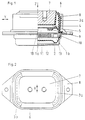
- the elastic rubber bearing shown in Figure 1 consists essentially of two fastening parts 7 and 8, which are connected to one another via an elastomer spring 6, wherein two independently operating damping devices are arranged within the elastic rubber bearing.
- the elastic rubber bearing has a relatively tight thrust-pressure characteristic in the direction of the axis Cx. This axis Cx runs perpendicular to the plane of the drawing.
- the elastomer spring 6 is provided with two chambers 3a and 3b, which are hydraulically connected to one another via a channel 4.
- the channel 4 is partially embedded in the fastening part 7 and is closed by the separating part 5.
- the fastening part 8 is provided with a partition 10 and a bellows 12, so that the chambers 1a and 1b are in hydraulic connection with one another via a channel 2 running in the partition 10.
- This damping device achieves hydraulic damping in the axis Cz.
- the separating part 5 is provided with a stop 9 which works together with the partition 10.
- the partition 10 is additionally provided with a decoupling membrane 11.
- the chamber 1b and the bellows 12 are protected from the atmosphere by a protective cap.
- the small diameter opening 15 is provided for pressure equalization between the chambers and the chamber.
- Figure 2 shows in plan view that the fastening parts 7 and 8 are arranged approximately rectangular, so that the thrust spring 6 runs essentially on the long side of the rubber bearing, while the thrust spring 6 in the region of the end faces with the chambers 3a and 3b with a corresponding hydraulic damping device is provided.
- the separating part 5 delimits the channel 4 in the fastening part 7 with respect to the chamber 1a.
- the chamber 1b serves as a volume-compensating compensation space, while a vent hole 14 is arranged in the protective cap 13 for a perfect pressure compensation.
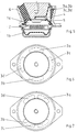
- FIG. 4 An elastic rubber bearing in the form of a circular bearing is shown in FIG. 4, the fastening parts 7 and 8 again being essentially removed, the chamber 3a via the channel 4 with the chamber 3b (not shown, since the left side is 90 degrees is shown offset).
- the chambers 1a and 1b are hydraulically connected to one another via the channel 2.
- the elastomer spring 6 extends conically around the fastening part 7 and is provided with the chambers 3a and 3b.
- FIG. 5 and the associated top view of FIG. 6 and FIG. 7 show a rubber bearing, in which chambers 3a, 3b, 3c, 3d are introduced into the elastomer spring 6 in two horizontal axes.
- damping can be achieved in one or more transverse directions.
- the chambers 3a, 3b, 3c, 3d can be arranged in accordance with FIG. 6 or in accordance with FIG. 7, so that a hard thrust-pressure characteristic curve in a horizontal direction can optionally be achieved in a certain area.
Landscapes
- Engineering & Computer Science (AREA)
- General Engineering & Computer Science (AREA)
- Mechanical Engineering (AREA)
- Combined Devices Of Dampers And Springs (AREA)
Abstract
Description
- Die Erfindung bezieht sich auf ein elastisches Gummilager, insbesondere für Kraftfahrzeuge, mit mindestens zwei Befestigungsteilen, die über eine Elastomerfeder miteinander verbunden sind, und mit einer vertikal wirkenden hydraulischen Dämpfungsvorrichtung und mindestens einer in horizontaler Richtung wirkenden hydraulischen Dämpfungsvorrichtung, bestehend aus mit Dämpfungsflüssigkeit gefüllten und über Dämpfungskanäle miteinander verbundenen Kammern.
- Es sind bereits elastische Gummilager bekannt (z.B. DE-PS 30 24 090), bei denen die Befestigungsteile über eine Elastomerfeder miteinander verbunden sind und zusätzlich eine hydraulische Dämpfungsvorrichtung aufweisen. Die Elastomerfeder ist dabei in eine äußere, ein- oder mehrteilige Schubfeder und in eine innere sich über einen Grundkörper am Befestigungsteil abstützende, ringförmige Gummifeder aufgeteilt. Durch diese Ausbildung wird von der inneren ringförmigen Gummifeder nur ein geringer Anteil der Lagerlast aufgenommen, wobei eine Dämpfung der niederfrequenten Schwingungen in Hochrichtung erreicht wird. Nachteilig ist bei einem derartigen Lager, daß in der weichen Schubrichtung keine Dämpfung erfolgen kann, so daß durch die weichen kleinen Federkonstanten der Elastomerfeder große ungedämpfte Bewegungen möglich sind, so daß ein Aufschaukeln bei Resonanz auftreten kann.
- Darüber hinaus sind Gummilager bekannt (z.B. EP-PS 0.042.761), bei denen die Befestigungsteile über eine Elastomerfeder miteinander verbunden sind. Das Gummilager ist mit einer in horizontaler und mit einer in vertikaler Richtung wirkenden Dämpfungsvorrichtung versehen. Nachteilig ist dabei, daß die einfache Ausführungsform eine geringe Wirkungsweise erwarten läßt.
- Aufgabe der Erfindung ist es, ein elastisches Gummilager so zu verbessern, daß die Übertragung von Schwingungen in vertikaler und in mindestens einer horizontalen Richtung wirkungsvoll gedämpft werden kann, wobei die horizontale Dämpfung entweder in Fahrzeuglängsrichtung, z.B. Fahrwerkslagerungen, und/oder in Fahrzeugquerrichtung, z.B. Motorlagerungen, erforderlich sein kann.
- Zur Lösung dieser Aufgabe ist erfindungsgemäß vorgesehen, daß die horizontal wirkende Dämpfungsvorrichtung aur. mindestens zwei gegenüberliegenden, in die Elastomerfeder eingeformte und nach unten offene Kammern und mindestens einen, die Kammern verbindenden Kanal besteht, wobei die Kammern nach unten durch ein Trennteil begrenzt sind, daß unterhalb eines Trennteiles eine zweite, in Richtung der vertikalen Cz-Koordinatenachse ausgerichtete Dämpfungsvorrichtung vorgesehen ist, deren Kammern in Richtung der Cz-Koordinatenachse hintereinanderliegend angeordnet und über den Kanal miteinander verbunden sind.
- Bei dieser Ausbildung ist von Vorteil, daß das Lager bei Verwendung von zwei Kammern als Fahrwerkslager hohe Seitenführungskräfte in Richtung Cy, ferner die Aufnahme großer Vertikalkräfte und Dämpfung von vertikalen Schwingungen gewährleistet und dabei gleichzeitig in Fahrzeuglängsrichtung durch eine weiche Federkennlinie Cx und Dämpfung hoher Abrollkomfort erzielt wird. Bei Verwendung des Lagers als Motorlager, mit ebenfalls zwei Kammern, können in Richtung Cz hohe Traglasten aufgenommen und Schwingungen gedämpft werden, in Richtung Cx können große Bremskräfte abgefangen werden, und in Richtung Cy kann bei weicher Federkennlinie das Querschütteln des Motors wirkungsvoll gedämpft werden.
- In wesentlicher Ausgestaltung der Erfindung ist vorgesehen, daß das Gummilager in einer horizontalen Koordinatenachse eine weiche Schubkennlinie und in der anderen horizontalen Koordinatenachse eine harte Kennlinie aufweist, und daß die horizontale Dämpfvorrichtung in Richtung der weichen Schubkennlinie angeordnet ist.
- Bei Verwendung von mehr als zwei Kammern in Verbindung mit mindestens einem Dämpfungskanal läßt sich nach Belieben eine Dämpfung in mehreren Querrichtungen erzielen.
- In einer möglichen Ausgestaltung der Erfindung ist das Gummilager als Rundlager oder als Rechtecklager ausgebildet.
- Nach einem weiteren wesentlichen Merkmal ist vorgesehen, daß die Kammern in der Elastomerfeder diametral gegenüberliegend zu beiden Seiten eines der Befestigungsteile angeordnet sind. Dabei werden mit Vorteil die Wandungen des Kanales von einem der Befestigungsteile und einem Trennteil gebildet. Mit Vorteil können darüber hinaus jeweils zwei Kammern über jeweils einen Kanal miteinander verbunden werden.
- Eine fertigungstechnisch einfache Ausführungsform sieht vor, daß das Trennteil die Kammern und die Kammer gegeneinander trennt. Vorteilhaft ist hierbei, daß die Dämpfvorrichtung für vertikale Dämpfung im Bereich der Lagerachse unterhalb der Elastomerfeder und des Trennteiles angeordnet werden kann.
- Nach einer günstigen Ausführungsform ist vorgesehen, daß das Trennteil mit einem Axialanschlag versehen ist.
- In Ausgestaltung der Erfindung ist die Kammer als volumenausgleichender Ausgleichsraum ausgebildet. Hierbei läßt sich in vorteilhafter Weise eine Schutzkappe vorsehen, wobei gegebenenfalls die Schutzkappe mit einer Entlüftungsbohrung zum Druckausgleich gegenüber dem Ausgleichsraum versehen ist.
- Anstatt geradliniger Bohrungen zwischen den einzelnen Kammern ist nach einem weiteren wesentlichen Merkmal vorgesehen, daß mindestens einer der Kanäle als ringformig um die Lagerachse verlaufender Dämpfungskanal ausgebildet ist. Mit Vorteil ist dabei der Kanal in einer die Kammern trennenden Trennwand angeordnet. Diese Trennwand läßt sich zusätzlich noch mit einer Entkopplungsmembran versehen.
- In weiterer Ausgestaltung ist vorgesehen, daß der Kanal als Bohrung im Befestigungsteil ausgebildet ist.
- Nach einem weiteren wesentlichen Merkmal ist mindestens eine Kammer mit einer Entkopplungsmembran versehen und/oder parallel zum Dämpfungskanal mindestens ein Bypaßventil angeordnet.
- Eine günstige Ausführungsform sieht vor, daß in dem Trennteil eine Öffnung für den Druckausgleich zwischen den Kammern und den Kammern vorgesehen ist.
- Bevorzugte Ausführungsbeispiele der Erfindung sind in den Zeichnungen schematisch dargestellt.
- Es zeigt:
- Figur 1 ein als Motorlager ausgebildetes elastisches Gummilager, teils geschnitten
- Figur 2 eine Draufsicht des in Figur 1 dargestellten Gummilagers
- Figur 3 eine Seitenansicht des in Figur 1 dargestellten Gummilagers teils geschnitten
- Figur 4 ein Gummilager im Prinzip wie in Figur 1 bereits dargestellt, jedoch als Rundlager ausgebildet.
- Figur 5 - 7 weitere Ausführungsformen eines Gummilagers mit vier Kammern.
- Das in Figur 1 dargestellte elastische Gummilager besteht im wesentlichen aus zwei Befestigungsteilen 7 und 8, die über eine Elastomerfeder 6 miteinander verbunden sind, wobei innerhalb des elastischen Gummilagers zwei unabhängig voneinander arbeitende Dämpfungsvorrichtungen angeordnet sind. Das elastische Gummilager weist in Richtung der Achse Cx eine verhältnismäßig straffe Schub-Druckkennlinie auf. Diese Achse Cx verläuft senkrecht zur Zeichenebene.
- Die Elastomerfeder 6 ist mit zwei Kammern 3a und 3b versehen, welche über einen Kanal 4 hydraulisch miteinander in Verbindung stehen. Der Kanal 4 ist im Befestigungsteil 7 teilweise eingelassen und wird durch das Trennteil 5 geschlossen. Durch diese Dämpfvorrichtung wird in der Achse Cy eine hydraulische Dämpfung mittels der Kammern 3a und 3b und dem Kanal 4 erzielt.
- Das Befestigungsteil 8 ist mit einer Trennwand 10 und einem Faltenbalg 12 versehen, so daß die Kammern 1a und 1b über einen in der Trennwand 10 verlaufenden Kanal 2 miteinander in hydraulischer Verbindung stehen. Durch diese Dämpfungsvorrichtung wird in der Achse Cz eine hydraulische Dämpfung erreicht. Gegenüber einem zu starken vertikalen Einfedern des Befestigungsteiles 7 ist das Trennteil 5 mit einem Anschlag 9 versehen, der mit der Trennwand 10 zusammen arbeitet.
- Die Trennwand 10 ist zusätzlich mit einer Entkopplungsmembran 11 versehen.
- Die Kammer 1b und der Faltenbalg 12 sind gegen die Atmosphäre durch eine Schutzkappe geschützt.
- Im Trennteil 5 ist die im Durchmesser kleine Öffnung 15 für den Druckausgleich zwischen den Kammern und der Kammer vorgesehen.
- Die Figur 2 zeigt in Draufsicht, daß die Befestigungsteile 7 und 8 in etwa rechteckig angeordnet sind, so daß die Schubfeder 6 im wesentlichen an der Längsseite des Gummilagers verläuft, während die Schubfeder 6 im Bereich der Stirnseiten mit den Kammern 3a und 3b mit einer entsprechenden hydraulischen Dämpfvorrichtung versehen ist.
- Aus der Figur 3 ist in der Seitenansicht zu entnehmen, daß das Trennteil 5 den Kanal 4 im Befestigungsteil 7 gegenüber der Kammer 1a abgrenzt. Die Kammer 1b dient als volumenausgleichender Ausgleichsraum, während zu einem einwandfreien Druckausgleich in der Schutzkappe 13 eine Entlüftungsbohrung 14 angeordnet ist.
- Aus der Figur 4 ist ein elastisches Gummilager in Form eines Rundlagers dargestellt, wobei wiederum im wesentlichen die Befestigungsteile 7 und 8 zu entnehmen sind, wobei die Kammer 3a über den Kanal 4 mit der Kammer 3b (nicht dargestellt, da die linke Seite um 90 Grad versetzt gezeichnet ist) in Verbindung steht. Die Kammern 1a und 1b sind über den Kanal 2 hydraulisch miteinander in Verbindung. Die Elastomerfeder 6 verläuft kegelförmig um das Befestigungsteil 7 und ist mit den Kammern 3a und 3b versehen.
- In der Figur 5 und der zugehörigen Draufsicht der Figur 6 bzw. der Figur 7 ist ein Gummilager dargestellt, bei dem in zwei horizontalen Achsen Kammern 3a, 3b, 3c, 3d in der Elastomerfeder 6 eingebracht sind. Durch eine Verbindung zweier Kammern oder aller Kammern über einen Kanal 4 läßt sich eine Dämpfung in einer oder meherer Querrichtungen erzielen. Die Kammern 3a, 3b, 3c, 3d lassen sich dabei gemäß Fig.6 oder gemäß Fig.7 anordnen, so daß gegebenenfalls in einem bestimmten Bereich eine harte Schub-Druckkennlinie in einer horizontalen Richtung erreicht werden kann.
-
- 1a
- - Kammer
- 1b
- - Kammer
- 2
- - Kanal
- 3a
- - Kammer
- 3b
- - Kammer
- 3c
- - Kammer
- 3d
- - Kammer
- 4
- - Kanal
- 5
- - Trennteil
- 6
- - Elastomerfeder
- 7
- - Befestigungsteil
- 8
- - Befestigungsteil
- 9
- - Anschlag
- 10
- - Trennwand
- 11
- - Entkopplungsmembran
- 12
- - Faltenbalg
- 13
- - Schutzkappe
- 14
- - Entlüftungsbohrung
- 15
- - Öffnung
Claims (17)
- Elastisches Gummilager, insbesondere für Kraftfahrzeuge, mit mindestens zwei Befestigungsteilen, die über eine Elastomerfeder miteinander verbunden sind, und mit einer vertikal wirkenden hydraulischen Dämpfungsvorrichtung und mindestens einer in horizontaler Richtung wirkenden hydraulischen Dämpfungsvorrichtung, bestehend aus mit Dämpfungsflüssigkeit gefüllten und über Dämpfungskanäle miteinander verbundenen Kammern,
dadurch gekennzeichnet,
daß die horizontal wirkende Dämpfungsvorrichtung aus mindestens Zwei gegenüberliegenden, in die Elastomerfeder eingeformte und nach unten offene Kammern (3a, 3b) und mindestens einen, die Kammern verbindenden Kanal besteht, wobei die Kammern (3a, 3b) nach unten durch ein Trennteil (5) begrenzt sind, daß unterhalb eines Trennteiles (5) eine zweite, in Richtung der vertikalen Cz-Koordinatenachse ausgerichtete Dämpfungsvorrichtung vorgesehen ist, deren Kammern (1a und 1b) in Richtung der Cz-Koordinatenachse hintereinanderliegend angeordnet und über den Kanal (2) miteinander verbunden sind. - Gummilager nach Anspruch 1,
dadurch gekennzeichnet,
daß das Gummilager in einer horizontalen Koordinatenachse eine weiche Schubkennlinie und in der anderen horizontalen Koordinatenachse eine harte Kennlinie aufweist, und daß die horizontale Dämpfvorrichtung in Richtung der weichen Schubkennlinie angeordnet ist. - Gummilager nach Anspruch 1,
dadurch gekennzeichnet,
daß das Gummilager als Rechtecklager ausgebildet ist. - Gummilager nach Anspruch 1,
dadurch gekennzeichnet,
daß das Gummilager als Rundlager ausgebildet ist. - Gummilager nach Anspruch 1,
dadurch gekennzeichnet,
daß die Kammern (3a, 3b) und/oder die Kammern (3c, 3d) in der Elastomerfeder (6) diametral gegenüberliegend zu beiden Seiten eines der Befestigungsteile (7) angeordnet sind. - Gummilager nach Anspruch 1,
dadurch gekennzeichnet,
daß die Wandungen des Kanales (4) von einem der Befestigungsteile (7 oder 8) und einem Trennteil (5) gebildet werden. - Gummilager nach Anspruch 1,
dadurch gekennzeichnet,
daß die Kammern (3a, 3b) und die Kammern (3c, 3d) über jeweils einen Kanal (4) miteinander verbunden sind. - Gummilager nach Anspruch 1,
dadurch gekennzeichnet,
daß das Trennteil (5) die Kammern (3a und 3b) und die Kammer (1a) gegeneinander trennt. - Gummilager nach Anspruch 1,
dadurch gekennzeichnet,
daß das Trennteil (5) mit einem Axialanschlag (9) versehen ist. - Gummilager nach Anspruch 1,
dadurch gekennzeichnet,
daß die Kammer (1b) als volumenausgleichender Ausgleichsraum ausgebildet ist. - Gummilager nach Anspruch 1,
dadurch gekennzeichnet,
daß mindestens einer der Kanäle (2 oder 4) als ringförmig um die Lagerachse verlaufender Dämpfungskanal ausgebildet ist. - Gummilager nach Anspruch 1,
dadurch gekennzeichnet,
daß der Kanal (2) in einer die Kammern (1a und 1b) trennenden Trennwand (10) angeordnet ist. - Gummilager nach Anspruch 1,
dadurch gekennzeichnet,
daß die Trennwand (10) mit einer Entkopplungsmembran (11) versehen ist. - Gummilager nach Anspruch 1,
dadurch gekennzeichnet,
daß der Kanal (4) als Bohrung im Befestigungsteil (7) ausgebildet ist. - Gummilager nach Anspruch 1,
dadurch gekennzeichnet,
daß mindestens eine Kammern (1a, 1b, 3a, 3b, 3c, 3d) mit einer Entkopplungsmembran (11) versehen ist. - Gummilager nach Anspruch 1,
dadurch gekennzeichnet,
daß parallel zu den Kanälen (2 und 4) mindestens ein Bypaßventil zwischen den Kammern (1a, 1b oder 3a, 3b, 3c, 3d) angeordnet ist. - Gummilager nach Anspruch 1,
dadurch gekennzeichnet,
daß in dem Trennteil (5) eine Öffnung (15) für den Druckausgleich zwischen den Kammern (3a, 3b) und den Kammern (1a,1b) vorgesehen ist.
Applications Claiming Priority (2)
| Application Number | Priority Date | Filing Date | Title |
|---|---|---|---|
| DE4216185 | 1992-05-15 | ||
| DE4216185A DE4216185C2 (de) | 1992-05-15 | 1992-05-15 | Elastisches Gummilager |
Publications (2)
| Publication Number | Publication Date |
|---|---|
| EP0569676A1 true EP0569676A1 (de) | 1993-11-18 |
| EP0569676B1 EP0569676B1 (de) | 1995-11-08 |
Family
ID=6459022
Family Applications (1)
| Application Number | Title | Priority Date | Filing Date |
|---|---|---|---|
| EP93103729A Expired - Lifetime EP0569676B1 (de) | 1992-05-15 | 1993-03-09 | Elastisches Gummilager |
Country Status (4)
| Country | Link |
|---|---|
| US (1) | US5386973A (de) |
| EP (1) | EP0569676B1 (de) |
| JP (1) | JPH06109061A (de) |
| DE (2) | DE4216185C2 (de) |
Cited By (2)
| Publication number | Priority date | Publication date | Assignee | Title |
|---|---|---|---|---|
| EP0809038A3 (de) * | 1996-05-24 | 1997-12-29 | Firma Carl Freudenberg | Hydrolager |
| EP1584837A1 (de) * | 2004-04-08 | 2005-10-12 | Hutchinson | Schwingungsdämpfungseinrichtung |
Families Citing this family (20)
| Publication number | Priority date | Publication date | Assignee | Title |
|---|---|---|---|---|
| DE4438932C2 (de) * | 1994-10-31 | 1998-07-02 | Daimler Benz Ag | Hydrolager |
| US5571263A (en) * | 1995-04-14 | 1996-11-05 | General Motors Corporation | Hydraulic engine mount with reduced impulse vibration |
| GB9526272D0 (en) * | 1995-12-21 | 1996-02-21 | Btr Plc | Hydraulic mounting |
| DE10064330A1 (de) * | 2000-12-21 | 2002-07-11 | Freudenberg Carl Kg | Hydrolager |
| US6612554B1 (en) * | 2001-10-24 | 2003-09-02 | The Goodyear Tire & Rubber Company | Hydraulic antivibration device |
| JP2005265061A (ja) * | 2004-03-18 | 2005-09-29 | Tokai Rubber Ind Ltd | 防振ブッシュ |
| US7097169B2 (en) * | 2004-08-04 | 2006-08-29 | Skf Usa Inc. | Elastomeric bearing with modified cylindrical core |
| JP2006064119A (ja) * | 2004-08-27 | 2006-03-09 | Tokai Rubber Ind Ltd | 流体封入式防振装置 |
| US20070090579A1 (en) * | 2005-10-21 | 2007-04-26 | Paulstra Crc | Hydraulic antivibration device |
| US7637486B2 (en) * | 2006-07-19 | 2009-12-29 | The Pullman Company | Very high damping body mount, subframe mount or engine mount with bolt-through construction |
| US8177201B2 (en) * | 2006-07-19 | 2012-05-15 | The Pullman Company | Very high damping mount with bolt-through construction |
| US8231115B2 (en) * | 2006-07-19 | 2012-07-31 | The Pullman Company | Very high damping body mount, subframe mount or engine mount with bolt-through construction |
| DE102008037471A1 (de) * | 2008-10-20 | 2010-04-29 | Contitech Vibration Control Gmbh | Hydrolager |
| DE102008054528A1 (de) * | 2008-12-11 | 2010-07-15 | Zf Friedrichshafen Ag | Axial dämpfendes Hydrolager |
| JP5325602B2 (ja) * | 2009-02-23 | 2013-10-23 | 東海ゴム工業株式会社 | 流体封入式防振装置 |
| DE102011102076B3 (de) * | 2011-05-19 | 2012-09-20 | Carl Freudenberg Kg | Hydrolager |
| JP6399882B2 (ja) * | 2014-10-06 | 2018-10-03 | 山下ゴム株式会社 | 防振装置 |
| CN107289064B (zh) * | 2016-03-31 | 2019-07-26 | 住友理工株式会社 | 方型流体封入式隔振装置 |
| DE102017112168B4 (de) * | 2017-06-01 | 2021-04-29 | Vibracoustic Gmbh | Trennvorrichtung zum Trennen einer Arbeitskammer und einer Ausgleichskammer eines hydraulisch dämpfenden Lagers sowie ein hydraulisch dämpfendes Lager |
| JP6449385B1 (ja) * | 2017-07-07 | 2019-01-09 | 住友理工株式会社 | 流体封入式防振装置 |
Citations (4)
| Publication number | Priority date | Publication date | Assignee | Title |
|---|---|---|---|---|
| DE3024090C1 (de) * | 1980-06-27 | 1981-10-01 | Boge Gmbh, 5208 Eitorf | Motorlager fuer Lastkraftwagen,Omnibusse o.dgl. Nutzfahrzeuge |
| EP0042761A2 (de) * | 1980-06-23 | 1981-12-30 | Bridgestone Tire Company Limited | Schwingungsisolierende Vorrichtung aus Gummi |
| FR2587429A1 (fr) * | 1985-09-13 | 1987-03-20 | Peugeot | Cale hydroelastique a au moins deux directions d'amortissement |
| US4962915A (en) * | 1989-07-18 | 1990-10-16 | Lord Corporation | Three-axis fluid-filled mount |
Family Cites Families (32)
| Publication number | Priority date | Publication date | Assignee | Title |
|---|---|---|---|---|
| DE2962362D1 (en) * | 1978-12-07 | 1982-04-29 | Peugeot | Elastic mounting, particularly for the suspension of a vehicle motor |
| JPS55149436A (en) * | 1979-05-10 | 1980-11-20 | Toyota Motor Corp | Vibration resisting rubber device |
| JPS5712139A (en) * | 1980-06-23 | 1982-01-22 | Bridgestone Corp | Vibration-proof rubber |
| DE3104708A1 (de) * | 1981-02-10 | 1982-08-26 | WOCO Franz-Josef Wolf & Co, 6483 Bad Soden-Salmünster | Dreikammerdaempfer |
| JPS5835065A (ja) * | 1981-08-24 | 1983-03-01 | Komatsu Ltd | ア−ク溶接における溶接位置検出方法 |
| JPS5937349A (ja) * | 1982-08-23 | 1984-02-29 | Tokai Rubber Ind Ltd | 防振支持体 |
| DE3402715A1 (de) * | 1984-01-26 | 1985-08-01 | Metzeler Kautschuk GmbH, 8000 München | Zweikammer-motorlager mit hydraulischer daempfung |
| JPS60184737A (ja) * | 1984-02-21 | 1985-09-20 | Honda Motor Co Ltd | 流体入りマウント |
| FR2563879B1 (fr) * | 1984-05-04 | 1988-08-26 | Hutchinson Sa | Support antivibratoire hydraulique |
| DE3443618A1 (de) * | 1984-11-29 | 1986-06-05 | Metzeler Kautschuk GmbH, 8000 München | Motorlager mit hydraulischer daempfung |
| CA1250824A (en) * | 1985-02-28 | 1989-03-07 | General Motors Corporation | Hydraulic-elastomeric mount |
| DE3521246A1 (de) * | 1985-06-13 | 1987-01-02 | Kaspar Lochner | Elastisches lager |
| FR2590344B1 (fr) * | 1985-11-18 | 1989-11-17 | Hutchinson Sa | Perfectionnements aux amortisseurs hydrauliques |
| US4742999A (en) * | 1986-05-16 | 1988-05-10 | Flower Wallace C | Quiet acting fluid filled vibration isolator having predictable low level high frequency minimum dynamic stiffness |
| JPS6330534A (ja) * | 1986-07-22 | 1988-02-09 | Sumitomo Electric Ind Ltd | フレキシブル印刷配線板用接着剤組成物 |
| DE3632670A1 (de) * | 1986-09-26 | 1988-04-07 | Boge Ag | Hydraulisch daempfendes gummilager |
| FR2605693B1 (fr) * | 1986-10-27 | 1989-04-28 | Hutchinson | Perfectionnements aux supports hydrauliques antivibratoires |
| US4783063A (en) * | 1987-01-30 | 1988-11-08 | General Motors Corporation | Hydraulic-elastomeric mount displacement decoupler |
| JPS6412153A (en) * | 1987-07-02 | 1989-01-17 | Tokai Rubber Ind Ltd | Fluid encapsulated mount |
| IT1211187B (it) * | 1987-07-07 | 1989-10-12 | Ages Spa | Supporto ammortizzante per la sospensione di un corpo oscillante ad una struttura di sopporto partico larmente per la sospensione del motore al telaio in un autoveicolo |
| US5005810A (en) * | 1987-07-09 | 1991-04-09 | Tokai Rubber Ind., Ltd. | Fluid-filled cushioning device having sealing arrangement for easy assembling |
| DE3730425A1 (de) * | 1987-09-10 | 1989-03-23 | Metzeler Gmbh | Hydraulisch daempfendes motorlager |
| GB8730005D0 (en) * | 1987-12-23 | 1988-02-03 | Avon Ind Polymers | Hydraulically damped mounting device |
| JPH01193425A (ja) * | 1988-01-27 | 1989-08-03 | Tokai Rubber Ind Ltd | 流体封入式マウント装置 |
| FR2628496B1 (fr) * | 1988-03-08 | 1990-12-21 | Peugeot | Liaison elastique a rigidification hydraulique |
| DE3808996A1 (de) * | 1988-03-17 | 1989-09-28 | Metzeler Gmbh | Hydraulisch daempfendes zweikammer - motorlager |
| JPH0625727Y2 (ja) * | 1988-08-23 | 1994-07-06 | 東海ゴム工業株式会社 | 流体封入式マウント装置 |
| DE3831644C2 (de) * | 1988-09-17 | 1998-08-27 | Pahl Gummi Asbest | Hydraulisch dämpfendes Lager |
| DE4031495A1 (de) * | 1990-10-05 | 1992-04-09 | Freudenberg Carl Fa | Hydraulisch daempfendes lager |
| DE4041837C1 (de) * | 1990-12-24 | 1992-04-30 | Boge Ag, 5208 Eitorf, De | |
| FR2672948B1 (fr) * | 1991-02-18 | 1993-06-04 | Hutchinson | Perfectionnements apportes aux dispositifs antivibratoires hydrauliques. |
| US5246211A (en) * | 1992-07-13 | 1993-09-21 | General Motors Corporation | Hydraulic mount with spring-loaded decoupler for tuned rate dip |
-
1992
- 1992-05-15 DE DE4216185A patent/DE4216185C2/de not_active Expired - Fee Related
-
1993
- 1993-03-09 DE DE59300880T patent/DE59300880D1/de not_active Expired - Fee Related
- 1993-03-09 EP EP93103729A patent/EP0569676B1/de not_active Expired - Lifetime
- 1993-04-09 JP JP5106021A patent/JPH06109061A/ja active Pending
- 1993-05-17 US US08/062,284 patent/US5386973A/en not_active Expired - Fee Related
Patent Citations (4)
| Publication number | Priority date | Publication date | Assignee | Title |
|---|---|---|---|---|
| EP0042761A2 (de) * | 1980-06-23 | 1981-12-30 | Bridgestone Tire Company Limited | Schwingungsisolierende Vorrichtung aus Gummi |
| DE3024090C1 (de) * | 1980-06-27 | 1981-10-01 | Boge Gmbh, 5208 Eitorf | Motorlager fuer Lastkraftwagen,Omnibusse o.dgl. Nutzfahrzeuge |
| FR2587429A1 (fr) * | 1985-09-13 | 1987-03-20 | Peugeot | Cale hydroelastique a au moins deux directions d'amortissement |
| US4962915A (en) * | 1989-07-18 | 1990-10-16 | Lord Corporation | Three-axis fluid-filled mount |
Non-Patent Citations (2)
| Title |
|---|
| PATENT ABSTRACTS OF JAPAN vol. 7, no. 141 (M-223)(1286) 21. Juni 1983 & JP-A-58 054 249 ( TOYODA GOSEI KK ) * |
| PATENT ABSTRACTS OF JAPAN vol. 8, no. 9 (M-268)(1446) 14. Januar 1984 & JP-A-58 170 934 ( NISSAN JIDOSHA KK ) 7. Oktober 1983 * |
Cited By (3)
| Publication number | Priority date | Publication date | Assignee | Title |
|---|---|---|---|---|
| EP0809038A3 (de) * | 1996-05-24 | 1997-12-29 | Firma Carl Freudenberg | Hydrolager |
| EP1584837A1 (de) * | 2004-04-08 | 2005-10-12 | Hutchinson | Schwingungsdämpfungseinrichtung |
| FR2868821A1 (fr) * | 2004-04-08 | 2005-10-14 | Hutchinson Sa | Dispositif antivibratoire |
Also Published As
| Publication number | Publication date |
|---|---|
| DE59300880D1 (de) | 1995-12-14 |
| EP0569676B1 (de) | 1995-11-08 |
| JPH06109061A (ja) | 1994-04-19 |
| DE4216185A1 (de) | 1993-11-18 |
| DE4216185C2 (de) | 1994-12-08 |
| US5386973A (en) | 1995-02-07 |
Similar Documents
| Publication | Publication Date | Title |
|---|---|---|
| EP0569676B1 (de) | Elastisches Gummilager | |
| DE69006230T2 (de) | Oberes Lager für Stossdämpfer in Aufhängungssystemen. | |
| DE68902107T2 (de) | Obere gelenkverbindung zwischen einer feder-daempfer-einheit und dem rahmen eines kraftfahrzeugs. | |
| DE4041837C1 (de) | ||
| DE69317541T2 (de) | Stossdämpfer | |
| EP0099526B1 (de) | Federelastische Aufhängung zur Lagerung insbesondere eines Fahrerhauses auf einem Fahrzeugchassis | |
| DE3139915A1 (de) | Luftgedaempftes gummilager | |
| DE2517799A1 (de) | Aufhaengevorrichtung fuer die karosserie sowie das triebwerk eines kraftwagens | |
| DE69013257T2 (de) | Obere Halterung für einen Radaufhängungsstossdämpfer mit elastisch gelagertem Resonanzglied. | |
| DE3040650A1 (de) | Vorrichtung zum koppeln und entkoppeln von zwei relativ zueinander bewegbaren teilen mittels einer laengenveraenderbaren lenkerstange | |
| DE3882824T2 (de) | Elastische Buchse mit Fluiddämpfung. | |
| DE3047641A1 (de) | Aufhaengung fuer fahrzeuge, insbesondere kraftfahrzeuge | |
| DE3827124A1 (de) | Stroemungsmittelgefuellte elastische montageeinheit | |
| DE1107031B (de) | Schwingungsdaempfendes Lager | |
| EP0375839B1 (de) | Hülsengummifeder | |
| DE3336204A1 (de) | Motorlager mit hydraulischer daempfung | |
| DE10029268A1 (de) | Hydraulisch gedämpfte Montagevorrichtung | |
| DE3829907A1 (de) | Montageeinheit aus elastomerem material mit hydraulischer daempfung fuer einen motor | |
| EP1145941A2 (de) | Lagerung einer Fahrerkabine an einem Fahrzeugrahmen | |
| DE3445684A1 (de) | Schwingungsdaempfer fuer fahrzeuge | |
| DE4010378C2 (de) | ||
| DE3432768C2 (de) | ||
| DE2616897A1 (de) | Bodenventil-anordnung fuer einen hydraulischen stossdaempfer | |
| DE4029228A1 (de) | Aggregatlagerung in einem kraftfahrzeug | |
| DE19812837A1 (de) | Hydraulisch dämpfendes Motorlager |
Legal Events
| Date | Code | Title | Description |
|---|---|---|---|
| PUAI | Public reference made under article 153(3) epc to a published international application that has entered the european phase |
Free format text: ORIGINAL CODE: 0009012 |
|
| AK | Designated contracting states |
Kind code of ref document: A1 Designated state(s): DE FR GB IT SE |
|
| 17P | Request for examination filed |
Effective date: 19940126 |
|
| 17Q | First examination report despatched |
Effective date: 19941111 |
|
| ITF | It: translation for a ep patent filed | ||
| GRAA | (expected) grant |
Free format text: ORIGINAL CODE: 0009210 |
|
| AK | Designated contracting states |
Kind code of ref document: B1 Designated state(s): DE FR GB IT SE |
|
| REF | Corresponds to: |
Ref document number: 59300880 Country of ref document: DE Date of ref document: 19951214 |
|
| ET | Fr: translation filed | ||
| GBT | Gb: translation of ep patent filed (gb section 77(6)(a)/1977) |
Effective date: 19960216 |
|
| PGFP | Annual fee paid to national office [announced via postgrant information from national office to epo] |
Ref country code: DE Payment date: 19960511 Year of fee payment: 4 |
|
| PLBE | No opposition filed within time limit |
Free format text: ORIGINAL CODE: 0009261 |
|
| 26N | No opposition filed | ||
| PGFP | Annual fee paid to national office [announced via postgrant information from national office to epo] |
Ref country code: GB Payment date: 19970228 Year of fee payment: 5 |
|
| PGFP | Annual fee paid to national office [announced via postgrant information from national office to epo] |
Ref country code: FR Payment date: 19970313 Year of fee payment: 5 |
|
| PGFP | Annual fee paid to national office [announced via postgrant information from national office to epo] |
Ref country code: SE Payment date: 19970319 Year of fee payment: 5 |
|
| PG25 | Lapsed in a contracting state [announced via postgrant information from national office to epo] |
Ref country code: DE Effective date: 19971202 |
|
| PG25 | Lapsed in a contracting state [announced via postgrant information from national office to epo] |
Ref country code: GB Free format text: LAPSE BECAUSE OF NON-PAYMENT OF DUE FEES Effective date: 19980309 |
|
| PG25 | Lapsed in a contracting state [announced via postgrant information from national office to epo] |
Ref country code: SE Free format text: LAPSE BECAUSE OF NON-PAYMENT OF DUE FEES Effective date: 19980310 |
|
| PG25 | Lapsed in a contracting state [announced via postgrant information from national office to epo] |
Ref country code: FR Free format text: THE PATENT HAS BEEN ANNULLED BY A DECISION OF A NATIONAL AUTHORITY Effective date: 19980331 |
|
| GBPC | Gb: european patent ceased through non-payment of renewal fee |
Effective date: 19980309 |
|
| EUG | Se: european patent has lapsed |
Ref document number: 93103729.5 |
|
| REG | Reference to a national code |
Ref country code: FR Ref legal event code: ST |
|
| PG25 | Lapsed in a contracting state [announced via postgrant information from national office to epo] |
Ref country code: IT Free format text: LAPSE BECAUSE OF NON-PAYMENT OF DUE FEES;WARNING: LAPSES OF ITALIAN PATENTS WITH EFFECTIVE DATE BEFORE 2007 MAY HAVE OCCURRED AT ANY TIME BEFORE 2007. THE CORRECT EFFECTIVE DATE MAY BE DIFFERENT FROM THE ONE RECORDED. Effective date: 20050309 |