EP0569720A1 - Dispositif frigorifique avec évaporateur - Google Patents
Dispositif frigorifique avec évaporateur Download PDFInfo
- Publication number
- EP0569720A1 EP0569720A1 EP93106013A EP93106013A EP0569720A1 EP 0569720 A1 EP0569720 A1 EP 0569720A1 EP 93106013 A EP93106013 A EP 93106013A EP 93106013 A EP93106013 A EP 93106013A EP 0569720 A1 EP0569720 A1 EP 0569720A1
- Authority
- EP
- European Patent Office
- Prior art keywords
- evaporator
- cooling device
- inner container
- fastening strips
- plate
- Prior art date
- Legal status (The legal status is an assumption and is not a legal conclusion. Google has not performed a legal analysis and makes no representation as to the accuracy of the status listed.)
- Granted
Links
Images
Classifications
-
- F—MECHANICAL ENGINEERING; LIGHTING; HEATING; WEAPONS; BLASTING
- F25—REFRIGERATION OR COOLING; COMBINED HEATING AND REFRIGERATION SYSTEMS; HEAT PUMP SYSTEMS; MANUFACTURE OR STORAGE OF ICE; LIQUEFACTION SOLIDIFICATION OF GASES
- F25D—REFRIGERATORS; COLD ROOMS; ICE-BOXES; COOLING OR FREEZING APPARATUS NOT OTHERWISE PROVIDED FOR
- F25D23/00—General constructional features
- F25D23/006—General constructional features for mounting refrigerating machinery components
-
- F—MECHANICAL ENGINEERING; LIGHTING; HEATING; WEAPONS; BLASTING
- F25—REFRIGERATION OR COOLING; COMBINED HEATING AND REFRIGERATION SYSTEMS; HEAT PUMP SYSTEMS; MANUFACTURE OR STORAGE OF ICE; LIQUEFACTION SOLIDIFICATION OF GASES
- F25D—REFRIGERATORS; COLD ROOMS; ICE-BOXES; COOLING OR FREEZING APPARATUS NOT OTHERWISE PROVIDED FOR
- F25D17/00—Arrangements for circulating cooling fluids; Arrangements for circulating gas, e.g. air, within refrigerated spaces
- F25D17/04—Arrangements for circulating cooling fluids; Arrangements for circulating gas, e.g. air, within refrigerated spaces for circulating air, e.g. by convection
Definitions
- the invention relates to a cooling device according to the preamble of claim 1.
- an evaporator for refrigerant is located in an inner container, which is provided for receiving goods to be cooled, and is arranged at a distance parallel to the vertical rear wall of the inner container.
- a partition that covers the evaporator from the useful interior of the inner container.
- This construction requires separate brackets for the evaporator and the partition.
- the invention has for its object to take measures in a refrigerator according to the preamble of claim 1, which allow attachment of the evaporator with simple means.
- the evaporator is fixed to fastening strips which are preferably formed in the corner region between the rear wall and the adjacent side walls.
- the evaporator then appears as part of the rear wall of the inner container.
- the fastening strips can, however, also be stepped, so that the side flanks of the step, which run into the depth, enclose the adjacent peripheral edges of the evaporator.
- At least the vertical side edges of the evaporator, but preferably also the upper and lower side edges, can be equipped with frame strips, which can optionally also be produced as an overmolded frame. With the frame strips, this evaporator can in turn be fixed on the mounting strips.
- the frame strips also cover pipe connections provided in the edge region of the evaporator or other irregularities or sharp edges.
- the evaporator can also be firmly connected to a plate on its side facing the useful space of the inner container, the edge regions of which can be fixed on the fastening strips.
- the contour of the evaporator can then be designed as desired and in particular can be narrower than the free space between the fastening strips.
- This plate can consist of a material that is matched in particular to the color of the inner container. However, it can also consist of heat-conducting and heat-storing material, so that the cold storage capacity of the evaporator is increased.
- the evaporator can also have ribs running vertically on its side surface facing the side wall of the inner container, or can be folded, the Folded edges run vertically.
- the evaporator has horizontal slots in the area of closed shelves arranged in the inner container and to allow cooling air deflectors to engage in the slots, through which the cooled air falling down flows into the space between two shelves, as a result of which one in each of these cooling zones own air circulation occurs.
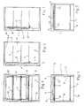
- An inner container 2 is located in a housing 1 of a refrigerator or freezer, the space between the housing 1 and the inner container 2 being especially foamed with thermal insulation 3.
- the inner container 2 sits parallel to the rear wall 4 with a small distance, for example 10 mm, single-plate evaporator 5, which is connected to a refrigeration circuit via pipes, not shown. From the open side 6 to be closed by a door, there are closed shelves 7 at different heights in the usable space for introducing goods to be cooled in front of the evaporator 5. If necessary, the evaporator 5 can also be arranged on one of the vertical side walls 8 or the top wall 8.1 of the inner container 2.
- fastening strips 9 are provided in the corner area at the transition from the rear wall 4 to the vertical side walls, which are raised above the level of the rear wall 4 to the opening side 6. These mounting strips 9 are preferably integrally connected to the inner container 2 and have been molded on during its manufacture.
- the evaporator 5, which is designed as a flat circuit board, is fixed at a distance from the rear wall 4 in the region of its vertical side edges 10 on these vertically extending fastening strips 9.
- the circuit board of the evaporator 5 is fixed directly to the mounting strips 9.
- the side edges 10 lie on the side of the fastening strip 9 facing the opening side 6. If the evaporator does not occupy the entire width between the side walls 8, it is expedient to step down the fastening strips so that the Side edges 10 of the evaporator 5 can be sunk into the fastening strip in such a way that the side edges 10 rest on the step flank running parallel to the rear wall 4 and the step flanks directed perpendicularly thereto and pointing into the inner container laterally cover the adjacent peripheral edge of the side edges 10.
- the evaporator 5 can also be provided with frame strips which have at least the vertical peripheral edges 10, but preferably also the upper and the Enclose the lower horizontal peripheral edge. These frame strips can be used instead of the vertical peripheral edge 10 for fastening the evaporator 5 to the fastening strips 9.
- FIGS. 4 and 5 it is also possible, according to FIGS. 4 and 5, to place a plate 11 completely covering the evaporator on the side of the evaporator facing the useful space of the inner container 2, that is to say the shelves 7.
- This plate 11 preferably overlaps all peripheral edges of the evaporator 5 and is firmly connected to the evaporator 5.
- the laterally projecting edge zones 12 of the plate 11 can in turn be used for fastening on the fastening strips 9.
- the plate 11 can in particular be matched in color to that of the inner container, so that there is an aesthetically pleasing rear closure of the inner container.
- the plate 11 can in particular consist of plastic if a simple covering and mounting for the evaporator 5 is desired. However, it can also consist of heat-conducting and heat-storing material, in particular sheet steel, if the heat capacity of the evaporator is to be increased.
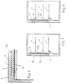
- its side surface facing the rear wall 4 may be provided with surface-enlarging elements, preferably ribs 13, which run parallel to one another in the vertical direction.
- the evaporator can also be folded, with the folded edges also extending vertically.
- the ribs 13 only cover the free part between the fastening strips 9.
- the evaporator 5 can also be provided with horizontally extending slots which are arranged in the height region of the shelf 7. Cooling air deflectors 15 engage in these slots 14 and lead the cooled air flowing downward in the gap between the rear wall 4 and the evaporator 5 onto the shelves 7.
- the cooling air deflectors 15 are designed as shapes of the rear wall 4. However, according to FIG. 8, they can also be produced as separate parts which are fixed in the area of the slots 14. It is also possible, however, to incline the flank of the evaporator 5 forming the lower edge of the slot 14 backwards into the gap between the evaporator 5 and the rear wall 4 in order to support a discharge of the cooled air to the respective shelf 7.
Landscapes
- Engineering & Computer Science (AREA)
- Chemical & Material Sciences (AREA)
- Combustion & Propulsion (AREA)
- Physics & Mathematics (AREA)
- Mechanical Engineering (AREA)
- Thermal Sciences (AREA)
- General Engineering & Computer Science (AREA)
- Cold Air Circulating Systems And Constructional Details In Refrigerators (AREA)
- Devices That Are Associated With Refrigeration Equipment (AREA)
Applications Claiming Priority (2)
| Application Number | Priority Date | Filing Date | Title |
|---|---|---|---|
| DE4215595A DE4215595C2 (de) | 1992-05-12 | 1992-05-12 | Kühlgerät mit Verdampfer |
| DE4215595 | 1992-05-12 |
Publications (2)
| Publication Number | Publication Date |
|---|---|
| EP0569720A1 true EP0569720A1 (fr) | 1993-11-18 |
| EP0569720B1 EP0569720B1 (fr) | 1995-12-27 |
Family
ID=6458660
Family Applications (1)
| Application Number | Title | Priority Date | Filing Date |
|---|---|---|---|
| EP93106013A Expired - Lifetime EP0569720B1 (fr) | 1992-05-12 | 1993-04-14 | Dispositif frigorifique avec évaporateur |
Country Status (3)
| Country | Link |
|---|---|
| EP (1) | EP0569720B1 (fr) |
| DE (2) | DE4215595C2 (fr) |
| ES (1) | ES2081652T3 (fr) |
Cited By (3)
| Publication number | Priority date | Publication date | Assignee | Title |
|---|---|---|---|---|
| WO2004015341A1 (fr) * | 2002-08-07 | 2004-02-19 | BSH Bosch und Siemens Hausgeräte GmbH | Appareil frigorifique avec interieur compartimente |
| WO2004102090A1 (fr) * | 2003-05-15 | 2004-11-25 | Multibrás S.A. Eletrodomésticos | Dispositif pour circulation d'air par convection dans des refrigerateurs |
| EP2392875A3 (fr) * | 2010-06-01 | 2015-06-03 | BSH Hausgeräte GmbH | Appareil frigorifique doté d'un évaporateur posé à l'intérieur |
Families Citing this family (2)
| Publication number | Priority date | Publication date | Assignee | Title |
|---|---|---|---|---|
| DE20005803U1 (de) * | 2000-03-29 | 2001-08-02 | Liebherr-Hausgeräte GmbH, 88416 Ochsenhausen | Befestigungselement |
| DE10057590B4 (de) * | 2000-11-21 | 2005-10-06 | Palux Ag | Kühleinrichtung |
Citations (7)
| Publication number | Priority date | Publication date | Assignee | Title |
|---|---|---|---|---|
| FR819817A (fr) * | 1937-03-27 | 1937-10-27 | Expanded Rubber Co Ltd | Perfectionnements apportés aux réfrigérants |
| FR1214411A (fr) * | 1957-11-25 | 1960-04-08 | Thomson Houston Comp Francaise | Structure d'évaporateur de dégivrage automatique |
| GB835190A (en) * | 1957-07-26 | 1960-05-18 | Westinghouse Electric Corp | Improvements in or relating to refrigeration apparatus |
| GB866140A (en) * | 1958-12-19 | 1961-04-26 | Gen Motors Corp | Improved household refrigerator |
| GB1025822A (en) * | 1962-02-09 | 1966-04-14 | Borg Warner | Refrigerator |
| EP0217121A1 (fr) * | 1985-09-12 | 1987-04-08 | INDUSTRIE ZANUSSI S.p.A. | Dispositif frigorifique avec un échangeur de chaleur collé à la paroi du compartiment frigorifique |
| EP0507754A2 (fr) * | 1991-04-03 | 1992-10-07 | Aktiebolaget Electrolux | Réfrigérateur avec des moyens de fixation d'un évaporateur |
Family Cites Families (5)
| Publication number | Priority date | Publication date | Assignee | Title |
|---|---|---|---|---|
| DE7329263U (de) * | 1974-05-02 | Bosch R Hausgeraete Gmbh | Kühlmöbel, insbesondere Kühl- oder Gefrierschrank | |
| DE1253733B (de) * | 1965-05-26 | 1967-11-09 | Siemens Elektrogeraete Gmbh | Kuehlschrank mit mindestens zwei Faechern verschiedener Temperatur |
| SE402816B (sv) * | 1975-09-12 | 1978-07-17 | Electrolux Ab | Anordning vid ett kylskap for fastsettning av organ inne i dess kylkammare |
| SU1145218A1 (ru) * | 1982-11-19 | 1985-03-15 | Grigorev Eduard N | Холодильник |
| SU1330425A1 (ru) * | 1986-04-14 | 1987-08-15 | Предприятие П/Я Г-4778 | Бытовой холодильник |
-
1992
- 1992-05-12 DE DE4215595A patent/DE4215595C2/de not_active Expired - Fee Related
-
1993
- 1993-04-14 DE DE59301232T patent/DE59301232D1/de not_active Expired - Fee Related
- 1993-04-14 ES ES93106013T patent/ES2081652T3/es not_active Expired - Lifetime
- 1993-04-14 EP EP93106013A patent/EP0569720B1/fr not_active Expired - Lifetime
Patent Citations (7)
| Publication number | Priority date | Publication date | Assignee | Title |
|---|---|---|---|---|
| FR819817A (fr) * | 1937-03-27 | 1937-10-27 | Expanded Rubber Co Ltd | Perfectionnements apportés aux réfrigérants |
| GB835190A (en) * | 1957-07-26 | 1960-05-18 | Westinghouse Electric Corp | Improvements in or relating to refrigeration apparatus |
| FR1214411A (fr) * | 1957-11-25 | 1960-04-08 | Thomson Houston Comp Francaise | Structure d'évaporateur de dégivrage automatique |
| GB866140A (en) * | 1958-12-19 | 1961-04-26 | Gen Motors Corp | Improved household refrigerator |
| GB1025822A (en) * | 1962-02-09 | 1966-04-14 | Borg Warner | Refrigerator |
| EP0217121A1 (fr) * | 1985-09-12 | 1987-04-08 | INDUSTRIE ZANUSSI S.p.A. | Dispositif frigorifique avec un échangeur de chaleur collé à la paroi du compartiment frigorifique |
| EP0507754A2 (fr) * | 1991-04-03 | 1992-10-07 | Aktiebolaget Electrolux | Réfrigérateur avec des moyens de fixation d'un évaporateur |
Cited By (3)
| Publication number | Priority date | Publication date | Assignee | Title |
|---|---|---|---|---|
| WO2004015341A1 (fr) * | 2002-08-07 | 2004-02-19 | BSH Bosch und Siemens Hausgeräte GmbH | Appareil frigorifique avec interieur compartimente |
| WO2004102090A1 (fr) * | 2003-05-15 | 2004-11-25 | Multibrás S.A. Eletrodomésticos | Dispositif pour circulation d'air par convection dans des refrigerateurs |
| EP2392875A3 (fr) * | 2010-06-01 | 2015-06-03 | BSH Hausgeräte GmbH | Appareil frigorifique doté d'un évaporateur posé à l'intérieur |
Also Published As
| Publication number | Publication date |
|---|---|
| DE4215595A1 (de) | 1993-11-18 |
| ES2081652T3 (es) | 1996-03-16 |
| DE4215595C2 (de) | 1995-05-11 |
| DE59301232D1 (de) | 1996-02-08 |
| EP0569720B1 (fr) | 1995-12-27 |
Similar Documents
| Publication | Publication Date | Title |
|---|---|---|
| EP0675332B1 (fr) | Réfrigérateur à rayons pour des marchandises à réfrigérer | |
| DE19609687C2 (de) | Wandkühlgerät für einen Schaltsschrank mit einem Lüfter und einem Lamellen-Wärmetauscher | |
| EP2414756B1 (fr) | Appareil frigorifique ménager | |
| WO1999026032A1 (fr) | Appareil refrigerant | |
| DE2928774A1 (de) | Gefrierschrank mit einem durch natuerliche konvektion gekuehlten, grossraeumigen gefrierraum | |
| CH671283A5 (fr) | ||
| EP3121543B1 (fr) | Appareil de refroidissement avec compartiment extractible | |
| EP0569720A1 (fr) | Dispositif frigorifique avec évaporateur | |
| DE19737531C2 (de) | Wärmetauscherbausatz und Klimatisierungsmeßgerät | |
| DE3234772C2 (de) | Kühlvitrine | |
| DE2942491A1 (de) | Kuehltruhe | |
| DE102009056426A1 (de) | Unterbaugruppenelement für ein Kühl- und/oder Gefriergerät, Kühl- und/oder Gefriergerät sowie Verfahren zur Montage eines Kühl- und/oder Gefriergerätes | |
| DE8210690U1 (de) | Einbaugerät, insbesondere in eine Küchenzeile einbaubarer Kühl- oder Gefrierschrank | |
| DE3810212C2 (fr) | ||
| DE60117808T2 (de) | Kühlschrank oder gefrierschrank | |
| EP1926946A2 (fr) | Appareil frigorifique sans givre | |
| EP0026443B1 (fr) | Dispositif pour évacuer la chaleur perdue de boîtiers d'appareillage électronique encastrés dans un bâti d'armoire | |
| EP0532870A1 (fr) | Appareil frigorifique, notamment un réfrigérateur ménager | |
| DE69716835T2 (de) | Belüftete Tropfwasserschale für Gasabsorptions-Kühlschränke | |
| DE3319865C2 (de) | Kühlgerät mit einer Nische für einen Motorkompressor | |
| DE19917974C2 (de) | Kühl- und/oder Gefriergerät mit einem im Innenraum angeordneten kältegenerierenden Bauteil | |
| DE8434381U1 (de) | Kuehlgeraet, insbesondere haushalts-kuehlschrank oder dgl. | |
| EP2392875A2 (fr) | Appareil frigorifique doté d'un évaporateur posé à l'intérieur | |
| DE69718978T2 (de) | Behälter zum Sammeln von Kondensat und Kühlgerät mit solchem Behälter | |
| DE102024115346A1 (de) | Kühl- und/oder Gefriergerät |
Legal Events
| Date | Code | Title | Description |
|---|---|---|---|
| PUAI | Public reference made under article 153(3) epc to a published international application that has entered the european phase |
Free format text: ORIGINAL CODE: 0009012 |
|
| AK | Designated contracting states |
Kind code of ref document: A1 Designated state(s): DE ES FR GB IT |
|
| 17P | Request for examination filed |
Effective date: 19940415 |
|
| 17Q | First examination report despatched |
Effective date: 19941110 |
|
| RAP1 | Party data changed (applicant data changed or rights of an application transferred) |
Owner name: AEG HAUSGERAETE GMBH |
|
| GRAA | (expected) grant |
Free format text: ORIGINAL CODE: 0009210 |
|
| AK | Designated contracting states |
Kind code of ref document: B1 Designated state(s): DE ES FR GB IT |
|
| REF | Corresponds to: |
Ref document number: 59301232 Country of ref document: DE Date of ref document: 19960208 |
|
| ET | Fr: translation filed | ||
| REG | Reference to a national code |
Ref country code: ES Ref legal event code: FG2A Ref document number: 2081652 Country of ref document: ES Kind code of ref document: T3 |
|
| ITF | It: translation for a ep patent filed | ||
| GBT | Gb: translation of ep patent filed (gb section 77(6)(a)/1977) |
Effective date: 19960226 |
|
| PLBE | No opposition filed within time limit |
Free format text: ORIGINAL CODE: 0009261 |
|
| 26N | No opposition filed | ||
| PGFP | Annual fee paid to national office [announced via postgrant information from national office to epo] |
Ref country code: GB Payment date: 19970401 Year of fee payment: 5 |
|
| PGFP | Annual fee paid to national office [announced via postgrant information from national office to epo] |
Ref country code: FR Payment date: 19970416 Year of fee payment: 5 |
|
| PGFP | Annual fee paid to national office [announced via postgrant information from national office to epo] |
Ref country code: ES Payment date: 19970423 Year of fee payment: 5 |
|
| PG25 | Lapsed in a contracting state [announced via postgrant information from national office to epo] |
Ref country code: GB Free format text: LAPSE BECAUSE OF NON-PAYMENT OF DUE FEES Effective date: 19980414 |
|
| PG25 | Lapsed in a contracting state [announced via postgrant information from national office to epo] |
Ref country code: ES Free format text: LAPSE BECAUSE OF NON-PAYMENT OF DUE FEES Effective date: 19980415 |
|
| PG25 | Lapsed in a contracting state [announced via postgrant information from national office to epo] |
Ref country code: FR Free format text: THE PATENT HAS BEEN ANNULLED BY A DECISION OF A NATIONAL AUTHORITY Effective date: 19980430 |
|
| GBPC | Gb: european patent ceased through non-payment of renewal fee |
Effective date: 19980414 |
|
| REG | Reference to a national code |
Ref country code: FR Ref legal event code: ST |
|
| PGFP | Annual fee paid to national office [announced via postgrant information from national office to epo] |
Ref country code: DE Payment date: 19990507 Year of fee payment: 7 |
|
| REG | Reference to a national code |
Ref country code: ES Ref legal event code: FD2A Effective date: 20000503 |
|
| PG25 | Lapsed in a contracting state [announced via postgrant information from national office to epo] |
Ref country code: DE Free format text: LAPSE BECAUSE OF NON-PAYMENT OF DUE FEES Effective date: 20010201 |
|
| PG25 | Lapsed in a contracting state [announced via postgrant information from national office to epo] |
Ref country code: IT Free format text: LAPSE BECAUSE OF NON-PAYMENT OF DUE FEES Effective date: 20050414 |