EP0569876A1 - Façade d'éléments - Google Patents
Façade d'éléments Download PDFInfo
- Publication number
- EP0569876A1 EP0569876A1 EP93107437A EP93107437A EP0569876A1 EP 0569876 A1 EP0569876 A1 EP 0569876A1 EP 93107437 A EP93107437 A EP 93107437A EP 93107437 A EP93107437 A EP 93107437A EP 0569876 A1 EP0569876 A1 EP 0569876A1
- Authority
- EP
- European Patent Office
- Prior art keywords
- facade
- profile
- horizontal
- vertical
- frame
- Prior art date
- Legal status (The legal status is an assumption and is not a legal conclusion. Google has not performed a legal analysis and makes no representation as to the accuracy of the status listed.)
- Granted
Links
Images



Classifications
-
- E—FIXED CONSTRUCTIONS
- E06—DOORS, WINDOWS, SHUTTERS, OR ROLLER BLINDS IN GENERAL; LADDERS
- E06B—FIXED OR MOVABLE CLOSURES FOR OPENINGS IN BUILDINGS, VEHICLES, FENCES OR LIKE ENCLOSURES IN GENERAL, e.g. DOORS, WINDOWS, BLINDS, GATES
- E06B7/00—Special arrangements or measures in connection with doors or windows
- E06B7/14—Measures for draining-off condensed water or water leaking-in frame members for draining off condensation water, throats at the bottom of a sash
Definitions
- the invention relates to an element facade with field-by-point drainage, the facade elements to be connected to a building or the like in each case having an element frame containing a filling with the frame sides forming vertical and horizontal frame legs in the facade and the adjacent facade elements on the mutually facing frame sides between them Opposing frame legs form expansion spaces, the frame legs have a supporting profile on the building side and a rebate profile on the facade side, and the expansion spaces have vertical and horizontal sealing strips in the facade, which connect the opposite frame legs and absorb their expansion movements against each other, into one supporting profile side and one folding profile side Expansion space part are separated.
- the support profiles of the frame legs have two in the direction perpendicular to the facade plane next to each other, separated by a web wall, in cross-section approximately U-shaped channel profiles, which are open to the outside of the frame and are circumferentially connected to each other at the frame corners, of which on each element frame the channel profile lying towards the outside of the facade receives the sealing strips, at least the vertical sealing strips in at least one of the two channel profiles belonging to adjacent element frames that accommodate them and one opposite the bottom of the channel profile the drainage channel serving for drainage leaves free that furthermore the part of the horizontal expansion space between the vertically adjacent facade elements on the vertical frame sides extends into the channel profiles lying towards the inside of the facade ifend and between themselves in the vertical expansion space between horizontally adjacent facade elements a free space, pushing against the web walls as well as on the respective upper horizontal frame sides face sealingly butting against the pushing channel profiles are used, which drain through openings in the pushing through into the space between the latter, that the two are opposite each other in
- a preferred embodiment of the invention because of its particular simplicity is characterized in that the recess of the horizontal sealing strip is formed by a profile shoulder provided on the strip, which runs at a free distance below the mouth of the drop channels which extend vertically above it in each case, this to the outside of the facade channel profile lying in the lower horizontal frame leg of the facade elements lying above the horizontal sealing strip and thus also the downcomers remain open at the bottom, that furthermore the horizontal sealing strip has a sealing lip under the profile shoulder and a sealing web running next to it and projecting upwards over the profile shoulder, from which the sealing lip engages in the channel profile lying towards the outside of the facade in the upper horizontal frame leg of the facade elements located below the sealing strip and the sealing web lies in the towards the inside of the facade Nden channel profiles on the two web walls, which is in the support profile side part of the expansion space to the face horizontal frame legs of the vertically adjacent facade elements.
- the lower ends of the vertical sealing strips each extending above the horizontal sealing strip can then also lie at a free distance above the profile shoulder, so that sealing connections between these ends and the horizontal sealing strips are unnecessary.
- the lower ends of the drop channels on each horizontal sealing strip are connected in a very simple manner via the profile shoulder to the outside of the facade.
- the support-profile-side part of the expansion spaces on the building side is closed in essentially the same way as for the rebate-side part of the expansion spaces by horizontal and vertical sealing strips, with the vertical sealing strips extending over the horizontal sealing strips only differently than there the bottom end of the ledge tightly against the profile shoulder of the horizontal sealing ledge.
- the same sealing strips can therefore be used for the building-side sealing of the expansion rooms on the supporting profile side as for the sealing to the rebate-side part of the expansion rooms.
- the element facade shown consists of facade elements 1, 1 ', which are arranged one above the other and side by side, each in a manner not belonging to the invention and therefore not shown in the drawing, connected to a building construction which is also not shown in the drawing.
- Each facade element 1, 1 ' consists of an element frame 2, in which a filling 3 is contained, which can be designed as panels (element 1') single or multi-glazed window panes (element 1) or in another suitable manner.
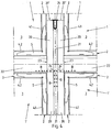
- the element frames 2 consist of the four frame sides 4.1, vertical and horizontal frame legs in the facade, 4.2, which are mitred in the frame corners and are held together by corner pieces 5 which can be seen in FIG. 4.
- the facade elements 1, 1 ′ which are adjacent in the facade, form expansion spaces on the mutually facing frame sides between the frame legs 4.1, 4.2 lying opposite one another, in which mutual movements of the element frames 2 are recorded.
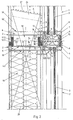
- the frame legs 4.1, 4.2 are of identical design on all four sides of the frame and have on the building side a support profile 6 and on the façade side a filler profile 3 receiving the fold profile 7, to which, depending on the type of filler, 3 adapter profiles 8 and filler retaining strips 9 are attached with the associated seals.
- An insulating insert 10 (elements 1 ') can also be held on the support profile 6.
- the support profile 6 and the folded profile 7 can be integrally formed with one another; in the exemplary embodiment, however, the support profiles 6 and the fold profiles 7 are each independently and positively joined at 11.
- the expansion spaces are separated by sealing strips 12, 13 running vertically and horizontally in the facade into an expansion space part 14 on the support profile side and an expansion space part 15 on the rebate profile side, the sealing strips 12, 13 connecting the frame legs 4.1, 4.2 lying opposite one another and absorbing their expansion movements relative to one another.
- the support profiles 6 of the frame legs 4.1, 4.2 form two channel profiles 17, 18, which run side by side in the direction perpendicular to the facade plane and are separated from one another by a web wall 16 and are approximately U-shaped in cross section, which are open to the outside of the frame and adjoin each other all around at the frame corners.
- the narrower duct profile 17 lying towards the outside of the facade takes the sealing strips 12, 13 on each element frame 2. At least the vertical sealing strips 12 do not completely fill the channel profile 17 which receives them, but rather leave a drop channel 19 serving for drainage between them and the channel base 17 '.
- sliders 20 designed as short pieces are inserted on the vertical frame legs 4.1, which overlap the part 14 of the horizontal expansion space on the supporting profile side between vertically adjacent facade elements 1, 1 'and leave a free space 21 between them in the vertical expansion space.
- the pushers 20 fill the channel profile 18 which receives them and in particular lie against the web walls 16.
- channel profiles 22 are inserted into the channel profiles lying towards the inside of the facade, which abut tightly against the sliding rings 20 at the front at 23 and drain through openings 24 in the sliding rings 20 into the space 21 between the sliding rings 20, such as it can be seen from FIGS. 4 and 5 at the rows B of points indicating the water flow.
- the end faces 20 'of the sliding blocks 20 including the seal 24 are inclined downwards in the direction towards the outside of the facade, as is indicated in FIG. 2 in dashed lines. At the bottom At the end, the end faces 20 'of the sliding blocks 20 connect to openings 25 which are provided in the web walls 16 and open into the drop channels 19.
- the horizontal sealing strips 13 run in gaps between the vertical sealing strips 12 and overlap the vertical expansion spaces between the horizontally adjacent facade elements 1 and 1 '.
- the vertical sealing strips 12 each running below them are sealed with their upper end, indicated by hatching 12 in FIG. 2, against the horizontal sealing strip 13, for example by means of a sealing compound.
- the horizontal sealing strips 13 are provided with recesses which are open towards the part 15 of the expansion space on the rebate profile side and are connected at the top with the drop channels 19 and through which the fall channels 19 drain into the rebate space part 15 on the rebate profile side.
- this recess of the horizontal sealing strip 13 is formed by a profile shoulder 13.1, which runs at a free distance below the end of the vertical sealing strips 12 and drop channels 19, which are indicated by hatching 12.6 in FIG.
- the horizontal sealing strips 13 each have a sealing lip 13.2 under the profile shoulder 13.1 and a sealing web 13.3 running next to this sealing lip, which protrudes upward above the profile shoulder 13.1.
- the sealing lip 13.2 engages in the channel profile 17 lying towards the outside of the facade in the upper horizontal frame leg 4.2 of the facade elements 1 'located in each case under the sealing strip 13.
- the sealing web 13.3 lies in the channel profiles 18 lying towards the inside of the facade against the two web walls 16, which face each other in the part 14 of the expansion space on the supporting profile side on the horizontal frame legs 4.2 of the respectively vertically adjacent facade elements 1, 1 '.
- the part of the sealing web which rests against the web wall 16 on the upper horizontal frame leg 4.2 of the facade elements 1 'located below the horizontal sealing strip 13 also seals the web wall 16 against the side wall 22' of the channel profile 22 inserted in this frame leg 4.2.
- the sealing of the part 14 of the expansion spaces on the supporting profile side on the building side takes place in essentially the same way as the sealing to the part 15 of the expansion spaces on the rebate side.
- the same horizontal and vertical sealing strips 12 ', 13' are used for this, the only difference being that the vertical sealing strips 12 'each extending over the horizontal sealing strips 13' with the lower strip end 12 "close to the profile shoulder 13.1 ' of the horizontal sealing strip 13 '.
Landscapes
- Engineering & Computer Science (AREA)
- Civil Engineering (AREA)
- Structural Engineering (AREA)
- Building Environments (AREA)
- Bipolar Transistors (AREA)
- Cold Cathode And The Manufacture (AREA)
- Surgical Instruments (AREA)
- Load-Bearing And Curtain Walls (AREA)
- Roof Covering Using Slabs Or Stiff Sheets (AREA)
- Finishing Walls (AREA)
Applications Claiming Priority (2)
| Application Number | Priority Date | Filing Date | Title |
|---|---|---|---|
| DE4214957 | 1992-05-11 | ||
| DE4214957A DE4214957C2 (de) | 1992-05-11 | 1992-05-11 | Elementfassade |
Publications (2)
| Publication Number | Publication Date |
|---|---|
| EP0569876A1 true EP0569876A1 (fr) | 1993-11-18 |
| EP0569876B1 EP0569876B1 (fr) | 1996-07-24 |
Family
ID=6458293
Family Applications (1)
| Application Number | Title | Priority Date | Filing Date |
|---|---|---|---|
| EP93107437A Expired - Lifetime EP0569876B1 (fr) | 1992-05-11 | 1993-05-07 | Façade d'éléments |
Country Status (5)
| Country | Link |
|---|---|
| EP (1) | EP0569876B1 (fr) |
| AT (1) | ATE140759T1 (fr) |
| DE (2) | DE4214957C2 (fr) |
| DK (1) | DK0569876T3 (fr) |
| ES (1) | ES2092174T3 (fr) |
Cited By (7)
| Publication number | Priority date | Publication date | Assignee | Title |
|---|---|---|---|---|
| EP0811730A3 (fr) * | 1996-06-04 | 1998-07-01 | Günter WERNER | Réseau de parecloses pour vitres d'une façade vitrée |
| GR980100080A (el) * | 1998-02-26 | 1999-10-29 | Συστημα ανοιγομενου κουφωματος αλουμινιου με καθολοκληριαν κεκλιμενες περι οριζοντιο αξονα προς τα εξω πλευρες στα τμηματα υποδοχης των υδατων και με συνδεση των κεκλιμενων επιπεδων υπο γωνιαν 90 μοιρων | |
| EP1849928A1 (fr) * | 2006-03-01 | 2007-10-31 | Norsk Hydro Asa | Dispositif destiné à drainer les bordures de cadre d'une façade rideau |
| FR2943083A1 (fr) * | 2009-03-12 | 2010-09-17 | Norsk Hydro As | Systeme d'assemblage de traverses horizontales et de montants verticaux d'une facade de type mur rideau |
| EP3031993A1 (fr) * | 2014-12-12 | 2016-06-15 | ALPIN Aluminium Produkt Innovation AG | Système et profil de mur rideau |
| WO2018073799A1 (fr) | 2016-10-21 | 2018-04-26 | Claeys Stephanie Catharina R | Mur-rideau et élément de mur utilisé et procédé de fabrication d'un tel élément de mur |
| BE1024680B1 (nl) * | 2016-10-21 | 2018-05-22 | Claeys Stephanie Catharina R. | Gordijngevel en daarbij toegepast gevelelement en werkwijze voor het fabriceren van dergelijk gevelelement. |
Families Citing this family (1)
| Publication number | Priority date | Publication date | Assignee | Title |
|---|---|---|---|---|
| DE10207552C1 (de) * | 2002-02-22 | 2003-07-03 | Hueck Eduard Gmbh Co Kg | Gebäudefassade |
Citations (4)
| Publication number | Priority date | Publication date | Assignee | Title |
|---|---|---|---|---|
| GB1145162A (en) * | 1966-06-16 | 1969-03-12 | Grossman Abraham | Curtain wall construction |
| GB2147930A (en) * | 1983-04-26 | 1985-05-22 | Yoshida Kogyo Kk | System for sealing cross joint of four adjacent curtain wall units |
| GB2167099A (en) * | 1984-11-17 | 1986-05-21 | Planet Windows | Water drainage in curtain walling |
| GB2244071A (en) * | 1990-04-25 | 1991-11-20 | Ykk Architectural | Weatherproof curtain wall |
Family Cites Families (1)
| Publication number | Priority date | Publication date | Assignee | Title |
|---|---|---|---|---|
| DE3540385A1 (de) * | 1985-11-14 | 1987-05-21 | Eltreva Ag | Fassadenkonstruktion aus metallprofilen |
-
1992
- 1992-05-11 DE DE4214957A patent/DE4214957C2/de not_active Expired - Fee Related
-
1993
- 1993-05-07 DE DE59303295T patent/DE59303295D1/de not_active Expired - Fee Related
- 1993-05-07 AT AT93107437T patent/ATE140759T1/de not_active IP Right Cessation
- 1993-05-07 ES ES93107437T patent/ES2092174T3/es not_active Expired - Lifetime
- 1993-05-07 EP EP93107437A patent/EP0569876B1/fr not_active Expired - Lifetime
- 1993-05-07 DK DK93107437.1T patent/DK0569876T3/da active
Patent Citations (4)
| Publication number | Priority date | Publication date | Assignee | Title |
|---|---|---|---|---|
| GB1145162A (en) * | 1966-06-16 | 1969-03-12 | Grossman Abraham | Curtain wall construction |
| GB2147930A (en) * | 1983-04-26 | 1985-05-22 | Yoshida Kogyo Kk | System for sealing cross joint of four adjacent curtain wall units |
| GB2167099A (en) * | 1984-11-17 | 1986-05-21 | Planet Windows | Water drainage in curtain walling |
| GB2244071A (en) * | 1990-04-25 | 1991-11-20 | Ykk Architectural | Weatherproof curtain wall |
Cited By (11)
| Publication number | Priority date | Publication date | Assignee | Title |
|---|---|---|---|---|
| EP0811730A3 (fr) * | 1996-06-04 | 1998-07-01 | Günter WERNER | Réseau de parecloses pour vitres d'une façade vitrée |
| GR980100080A (el) * | 1998-02-26 | 1999-10-29 | Συστημα ανοιγομενου κουφωματος αλουμινιου με καθολοκληριαν κεκλιμενες περι οριζοντιο αξονα προς τα εξω πλευρες στα τμηματα υποδοχης των υδατων και με συνδεση των κεκλιμενων επιπεδων υπο γωνιαν 90 μοιρων | |
| EP1849928A1 (fr) * | 2006-03-01 | 2007-10-31 | Norsk Hydro Asa | Dispositif destiné à drainer les bordures de cadre d'une façade rideau |
| FR2943083A1 (fr) * | 2009-03-12 | 2010-09-17 | Norsk Hydro As | Systeme d'assemblage de traverses horizontales et de montants verticaux d'une facade de type mur rideau |
| EP3031993A1 (fr) * | 2014-12-12 | 2016-06-15 | ALPIN Aluminium Produkt Innovation AG | Système et profil de mur rideau |
| WO2016091608A1 (fr) * | 2014-12-12 | 2016-06-16 | Alpin Aluminium Produkt Innovation Ag | Profil de mur-rideau et système |
| WO2018073799A1 (fr) | 2016-10-21 | 2018-04-26 | Claeys Stephanie Catharina R | Mur-rideau et élément de mur utilisé et procédé de fabrication d'un tel élément de mur |
| BE1024680B1 (nl) * | 2016-10-21 | 2018-05-22 | Claeys Stephanie Catharina R. | Gordijngevel en daarbij toegepast gevelelement en werkwijze voor het fabriceren van dergelijk gevelelement. |
| US11066829B2 (en) | 2016-10-21 | 2021-07-20 | Stephanie Catharina R. CLAEYS | Curtain wall and wall element thereby applied and method for manufacturing such a wall element |
| US11578485B2 (en) | 2016-10-21 | 2023-02-14 | Stephanie Catharina R. CLAEYS | Curtain wall and wall element thereby applied and method for manufacturing such a wall element |
| US11732473B2 (en) | 2016-10-21 | 2023-08-22 | Stephanie Catharina R. CLAEYS | Curtain wall and wall element thereby applied and method for manufacturing such a wall element |
Also Published As
| Publication number | Publication date |
|---|---|
| DE59303295D1 (de) | 1996-08-29 |
| ATE140759T1 (de) | 1996-08-15 |
| EP0569876B1 (fr) | 1996-07-24 |
| DE4214957A1 (de) | 1993-11-18 |
| DK0569876T3 (da) | 1996-08-26 |
| ES2092174T3 (es) | 1996-11-16 |
| DE4214957C2 (de) | 1996-03-28 |
Similar Documents
| Publication | Publication Date | Title |
|---|---|---|
| DE19647723C1 (de) | Rahmengestell für einen Schaltschrank | |
| DE3313444A1 (de) | Mechanismus zum ansetzen eines querpfostens an einen laengspfosten in einer blendwand | |
| EP1346112A2 (fr) | Fa ade ou toit a baguette d'etancheite pourvue d'une piece de remplissage | |
| EP0569876B1 (fr) | Façade d'éléments | |
| DE2916800C3 (de) | Anschluß eines Riegels an einen Pfosten einer Rahmenkonstruktion, insb. für vorgehängte Füllelemente, wie Scheiben, Paneele o.dgl. | |
| EP0100518A2 (fr) | Croisée à la française | |
| DE3808715C2 (fr) | ||
| DE202004005204U1 (de) | Schiebetür | |
| DE19649942C2 (de) | Aus Pfosten und Riegeln in Form von Hohlprofilen aufgebaute Rahmenkonstruktion | |
| EP0414105B1 (fr) | Dispositif de drainage, spécialement pour vitrage incliné et toit vitré | |
| DE4132064C1 (fr) | ||
| DE19600130A1 (de) | Schiebeverglasung | |
| DE3342166C2 (fr) | ||
| EP0726370A2 (fr) | Façade de bâtiment ou toit | |
| DE2723533B2 (de) | Fenster aus einem feststehenden Rahmen und einem Flügelrahmen | |
| DE4320321A1 (de) | Dachflächenfenster | |
| DE102016125334A1 (de) | Fenster oder Tür mit einer Dichtungsanordnung und Falzdichtung | |
| EP0340473B1 (fr) | Façade rideau | |
| DE3418071A1 (de) | Lueftungsfenster | |
| DE9216924U1 (de) | Rolladen mit Dichtungen | |
| CH669971A5 (en) | Profiled elastic window sealing component | |
| DE7906560U1 (de) | Rahmen fuer holzfenster | |
| DE8333529U1 (de) | Fassade | |
| AT503330B1 (de) | Profilschieneneinrichtung für eine mit glastafeln aufgebaute gebäude-fassade sowie glastafel hiefür | |
| WO2002053849A1 (fr) | Barre d'etancheite pour une façage et/ou un toit |
Legal Events
| Date | Code | Title | Description |
|---|---|---|---|
| PUAI | Public reference made under article 153(3) epc to a published international application that has entered the european phase |
Free format text: ORIGINAL CODE: 0009012 |
|
| 17P | Request for examination filed |
Effective date: 19930818 |
|
| AK | Designated contracting states |
Kind code of ref document: A1 Designated state(s): AT BE CH DE DK ES FR GB IT LI NL SE |
|
| GRAH | Despatch of communication of intention to grant a patent |
Free format text: ORIGINAL CODE: EPIDOS IGRA |
|
| 17Q | First examination report despatched |
Effective date: 19951201 |
|
| GRAH | Despatch of communication of intention to grant a patent |
Free format text: ORIGINAL CODE: EPIDOS IGRA |
|
| GRAA | (expected) grant |
Free format text: ORIGINAL CODE: 0009210 |
|
| RAP1 | Party data changed (applicant data changed or rights of an application transferred) |
Owner name: NORSK HYDRO A.S. |
|
| AK | Designated contracting states |
Kind code of ref document: B1 Designated state(s): AT BE CH DE DK ES FR GB IT LI NL SE |
|
| REF | Corresponds to: |
Ref document number: 140759 Country of ref document: AT Date of ref document: 19960815 Kind code of ref document: T |
|
| REG | Reference to a national code |
Ref country code: CH Ref legal event code: NV Representative=s name: ISLER & PEDRAZZINI AG |
|
| REG | Reference to a national code |
Ref country code: DK Ref legal event code: T3 |
|
| REF | Corresponds to: |
Ref document number: 59303295 Country of ref document: DE Date of ref document: 19960829 |
|
| ET | Fr: translation filed | ||
| GBT | Gb: translation of ep patent filed (gb section 77(6)(a)/1977) |
Effective date: 19960916 |
|
| ITF | It: translation for a ep patent filed | ||
| REG | Reference to a national code |
Ref country code: ES Ref legal event code: FG2A Ref document number: 2092174 Country of ref document: ES Kind code of ref document: T3 |
|
| PLBE | No opposition filed within time limit |
Free format text: ORIGINAL CODE: 0009261 |
|
| 26N | No opposition filed | ||
| PGFP | Annual fee paid to national office [announced via postgrant information from national office to epo] |
Ref country code: DE Payment date: 20000713 Year of fee payment: 8 |
|
| REG | Reference to a national code |
Ref country code: GB Ref legal event code: IF02 |
|
| PG25 | Lapsed in a contracting state [announced via postgrant information from national office to epo] |
Ref country code: DE Free format text: LAPSE BECAUSE OF NON-PAYMENT OF DUE FEES Effective date: 20020301 |
|
| PGFP | Annual fee paid to national office [announced via postgrant information from national office to epo] |
Ref country code: DK Payment date: 20020514 Year of fee payment: 10 |
|
| PG25 | Lapsed in a contracting state [announced via postgrant information from national office to epo] |
Ref country code: DK Free format text: LAPSE BECAUSE OF NON-PAYMENT OF DUE FEES Effective date: 20031201 |
|
| REG | Reference to a national code |
Ref country code: DK Ref legal event code: EBP |
|
| REG | Reference to a national code |
Ref country code: CH Ref legal event code: PCAR Free format text: ISLER & PEDRAZZINI AG;POSTFACH 1772;8027 ZUERICH (CH) |
|
| PGFP | Annual fee paid to national office [announced via postgrant information from national office to epo] |
Ref country code: FR Payment date: 20090513 Year of fee payment: 17 |
|
| PGFP | Annual fee paid to national office [announced via postgrant information from national office to epo] |
Ref country code: ES Payment date: 20100525 Year of fee payment: 18 |
|
| PGFP | Annual fee paid to national office [announced via postgrant information from national office to epo] |
Ref country code: NL Payment date: 20100514 Year of fee payment: 18 Ref country code: IT Payment date: 20100520 Year of fee payment: 18 Ref country code: AT Payment date: 20100513 Year of fee payment: 18 |
|
| PGFP | Annual fee paid to national office [announced via postgrant information from national office to epo] |
Ref country code: CH Payment date: 20100525 Year of fee payment: 18 Ref country code: BE Payment date: 20100517 Year of fee payment: 18 |
|
| PGFP | Annual fee paid to national office [announced via postgrant information from national office to epo] |
Ref country code: SE Payment date: 20100517 Year of fee payment: 18 |
|
| PGFP | Annual fee paid to national office [announced via postgrant information from national office to epo] |
Ref country code: GB Payment date: 20100819 Year of fee payment: 18 |
|
| REG | Reference to a national code |
Ref country code: FR Ref legal event code: ST Effective date: 20110131 |
|
| PG25 | Lapsed in a contracting state [announced via postgrant information from national office to epo] |
Ref country code: FR Free format text: LAPSE BECAUSE OF NON-PAYMENT OF DUE FEES Effective date: 20100531 |
|
| BERE | Be: lapsed |
Owner name: *NORSK HYDRO A/S Effective date: 20110531 |
|
| REG | Reference to a national code |
Ref country code: NL Ref legal event code: V1 Effective date: 20111201 |
|
| REG | Reference to a national code |
Ref country code: CH Ref legal event code: PL |
|
| REG | Reference to a national code |
Ref country code: SE Ref legal event code: EUG |
|
| GBPC | Gb: european patent ceased through non-payment of renewal fee |
Effective date: 20110507 |
|
| PG25 | Lapsed in a contracting state [announced via postgrant information from national office to epo] |
Ref country code: LI Free format text: LAPSE BECAUSE OF NON-PAYMENT OF DUE FEES Effective date: 20110531 Ref country code: CH Free format text: LAPSE BECAUSE OF NON-PAYMENT OF DUE FEES Effective date: 20110531 Ref country code: NL Free format text: LAPSE BECAUSE OF NON-PAYMENT OF DUE FEES Effective date: 20111201 |
|
| REG | Reference to a national code |
Ref country code: AT Ref legal event code: MM01 Ref document number: 140759 Country of ref document: AT Kind code of ref document: T Effective date: 20110507 |
|
| PG25 | Lapsed in a contracting state [announced via postgrant information from national office to epo] |
Ref country code: AT Free format text: LAPSE BECAUSE OF NON-PAYMENT OF DUE FEES Effective date: 20110507 Ref country code: IT Free format text: LAPSE BECAUSE OF NON-PAYMENT OF DUE FEES Effective date: 20110507 |
|
| PG25 | Lapsed in a contracting state [announced via postgrant information from national office to epo] |
Ref country code: BE Free format text: LAPSE BECAUSE OF NON-PAYMENT OF DUE FEES Effective date: 20110531 |
|
| PG25 | Lapsed in a contracting state [announced via postgrant information from national office to epo] |
Ref country code: GB Free format text: LAPSE BECAUSE OF NON-PAYMENT OF DUE FEES Effective date: 20110507 |
|
| REG | Reference to a national code |
Ref country code: ES Ref legal event code: FD2A Effective date: 20130417 |
|
| PG25 | Lapsed in a contracting state [announced via postgrant information from national office to epo] |
Ref country code: SE Free format text: LAPSE BECAUSE OF NON-PAYMENT OF DUE FEES Effective date: 20110508 Ref country code: ES Free format text: LAPSE BECAUSE OF NON-PAYMENT OF DUE FEES Effective date: 20110508 |