EP0569885A2 - Dispositif et procédé pour nettoyer un chariot pour le transport des plateaux d'alimentation ou similaires et chariot approprié - Google Patents
Dispositif et procédé pour nettoyer un chariot pour le transport des plateaux d'alimentation ou similaires et chariot approprié Download PDFInfo
- Publication number
- EP0569885A2 EP0569885A2 EP93107480A EP93107480A EP0569885A2 EP 0569885 A2 EP0569885 A2 EP 0569885A2 EP 93107480 A EP93107480 A EP 93107480A EP 93107480 A EP93107480 A EP 93107480A EP 0569885 A2 EP0569885 A2 EP 0569885A2
- Authority
- EP
- European Patent Office
- Prior art keywords
- cleaning
- carriage
- trolley
- trays
- housing
- Prior art date
- Legal status (The legal status is an assumption and is not a legal conclusion. Google has not performed a legal analysis and makes no representation as to the accuracy of the status listed.)
- Granted
Links
Images


Classifications
-
- B—PERFORMING OPERATIONS; TRANSPORTING
- B60—VEHICLES IN GENERAL
- B60S—SERVICING, CLEANING, REPAIRING, SUPPORTING, LIFTING, OR MANOEUVRING OF VEHICLES, NOT OTHERWISE PROVIDED FOR
- B60S3/00—Vehicle cleaning apparatus not integral with vehicles
- B60S3/04—Vehicle cleaning apparatus not integral with vehicles for exteriors of land vehicles
-
- A—HUMAN NECESSITIES
- A47—FURNITURE; DOMESTIC ARTICLES OR APPLIANCES; COFFEE MILLS; SPICE MILLS; SUCTION CLEANERS IN GENERAL
- A47L—DOMESTIC WASHING OR CLEANING; SUCTION CLEANERS IN GENERAL
- A47L15/00—Washing or rinsing machines for crockery or tableware
- A47L15/26—Washing or rinsing machines for crockery or tableware with movement of the crockery baskets by other means
- A47L15/30—Washing or rinsing machines for crockery or tableware with movement of the crockery baskets by other means by rotating only
-
- B—PERFORMING OPERATIONS; TRANSPORTING
- B08—CLEANING
- B08B—CLEANING IN GENERAL; PREVENTION OF FOULING IN GENERAL
- B08B3/00—Cleaning by methods involving the use or presence of liquid or steam
- B08B3/02—Cleaning by the force of jets or sprays
Definitions
- the invention relates to a device for cleaning at least one trolley for transporting food trays or the like, in particular serving trolleys for aircraft on-board service, the trolley being open at least on one side for loading and unloading trays.
- the device comprises a housing which has a closable inlet opening and is designed to receive the carriage, a drive device by means of which the carriage can be moved, a cleaning device, and a control device for the operation of the drive device and the cleaning device.
- the invention further relates to a method for cleaning such trolleys, comprising the steps of: feeding the trolley into a cleaning device, moving the trolley past the cleaning device and thus cleaning the trolley, and controlling the movement of the trolley and the cleaning process.
- the device and the method for cleaning trolleys for transporting dining trays or the like in the present invention are generally serving trolleys or the like which are used for the transport of a large number of dining trays, in particular for on-board service in airplanes, but also for Distribution of food on trays in nursing homes, such as Hospitals or retirement homes.
- these trolleys have an elongated box-like shape, which is either open on one or both narrow sides or ends for loading and unloading dining trays and can be closed by means of double doors.
- vehicles are used in the on-board service, the sizes of which have a standard size or half of them.
- the car interior can be divided by an open or closed partition, which causes particular problems when cleaning these cars, since the car interior must then be cleaned from both sides.
- the trolleys are usually made of aluminum or coated plastic and run on castors that can be braked together using either a handle or a pedal.
- the gullwing doors can be swiveled by 270 ° for loading and unloading.
- the inner side walls of the trolleys have horizontal grooves or rails into which the food trays are inserted one above the other. When cleaning the wagon, these inner side walls must be taken into account in particular, since the grooves or rails represent storage areas for the accumulation of dirt.
- a device and a method of the aforementioned type are disclosed in DE-A-3 828 035.
- serving trolleys are fed to the cleaning machine, opened, prewashed, washed, rinsed, dried and discharged, being conveyed through the machine at least from washing to drying by a conveyor belt.
- the wagons are moved with their open sides transversely to the conveying direction of the wagons along the cleaning line, with horizontally directed spray or air jets in the zones arranged one behind the other in the conveying direction for prewashing, washing, rinsing and drying Impact the exterior and interior of the car from the side.
- arranging the individual cleaning zones one behind the other along the conveyor belt means that the cleaning device is very long.
- targeted cleaning in particular of the interior of the vehicle, cannot be achieved, since the particularly dirty side walls of the vehicle are moved past them parallel to the spray jets directed transversely to the conveying direction.
- patent claims 15 to 17 finally specify a trolley specially designed for this purpose.
- a rotating device for the carriage is provided in the housing of the device, which can be rotated by the drive device. Furthermore, the rotational movement of the rotating device and the operation of the Cleaning device controllable in dependence on each other by the control device.
- the movement of the carriage is carried out as a rotary movement and the rotary movement and the cleaning process are controlled as a function of one another.
- the particular design of the box-shaped car to be cleaned with at least one open side has the consequence that access to the interior of the car for cleaning is only through the open side or the open sides, although this interior is usually the most is contaminated by leftovers and the like.
- the needs for cleaning the car and in particular the car interior are taken into account.
- the turning of the trolley according to the invention and the control of this rotary movement and the respective cleaning processes, such as blowing out, washing, rinsing and drying in relation to one another, results in a particularly advantageous cleaning, since the different areas of the trolley and in particular the heavily soiled areas are specifically cleaned by appropriate control can be.
- the control of the rotary movement as a function of the cleaning process has the particular advantage that the carriage is always brought into the optimal position in relation to the corresponding elements of the cleaning device for blowing out, washing, rinsing or drying.
- the device and the method of the present invention result in the further essential advantage that this particularly good cleaning effect can be reliably ensured with a very small space requirement.
- the compact design of the device according to the invention and the small space requirement of the method according to the invention are advantageously achieved in that only one rotary movement of the carriage is provided and that this rotary movement is controlled as a function of the individual cleaning steps of the cleaning process.
- the need to have enough time for each cleaning step of the cleaning process to ensure a sufficient cleaning effect during the movement of the carriage has so far been solved only by providing a very long carriage conveyor system in which the individual cleaning processes are carried out one after the other along a conveyor belt had to.
- This expensive and space-consuming system is advantageously eliminated by the inventive design, since only a rotary movement of the carriage on the individual stationary elements of the cleaning device and thus a much simpler structure is required.
- the turning device is a turntable provided in the area of the housing base, which ensures easy loading and unloading of the wagons.
- the rotary table is preferably mounted so as to be rotatable about a centrally arranged, vertical shaft or a gate-like yoke frame, which is connected to the drive device provided in the area of the ceiling of the housing.
- the wagons to be cleaned can then be loaded on both sides of the shaft.
- the centrally arranged shaft is designed to be removable and can be replaced by a gate-like yoke frame. This has the advantage that the entire contact surface of the turntable is available when a very large trolley is to be cleaned.
- the disposal device is generally located in the bottom area of the housing, a particularly compact configuration of the cleaning device according to the invention would not be achievable if the drive device which was to be serviced relatively often were also located in this area. Due to the arrangement on the top of the housing, it is now easily accessible, and a compact design of the housing is still possible.
- a holding device is provided on the turntable, which positions and holds the carriage for the cleaning process. It is particularly advantageous that the holding device is a cross bracket that fixes the carriage at four points.
- the cleaning device can have a washing device which has stationary connection and outlet fittings for cleaning liquid.
- the connection fitting preferably has spray nozzles which can be attached linearly vertically, in order thus to wash the carriage to ensure its entire height.
- the connection and outlet fittings for cleaning fluid can be connected to a heating device, such as a water heater or the like.
- the cleaning device can have a disposal device for discharging waste water, which has a tank in the area of the housing base, in which the cleaning liquid, such as circulated water, is initially collected.
- the tank for collecting the circulated water of the cleaning device can be designed in the bottom region of the housing as a trough which runs over the entire floor surface and at a slope to the water pumps and to the drain valve.
- the floor pan which serves as a storage tank for the cleaning liquid, is designed to be extremely flat and, for example, is only 350 mm deep. This enables effortless loading of wagons via a flat ramp.
- the device according to the invention is preferably lowered into a floor depression of a corresponding depth in order to enable the carriages to be retracted without an incline. This eliminates the need for lifting tables or other complex and risky lifting mechanisms, such as are required for truck cleaning machines of known types with insertion heights of approx. 900 mm.
- the tank preferably has one or more loosely inserted flat sieves and at least one sieve basket, which are arranged in such a way that waste particles are filtered out of the cleaning liquid circuit and optionally washed into the sieve baskets arranged parallel to the flat sieves.
- both the flat sieves and the Removable strainer baskets can also be connected to one or more water pumps, for example designed as centrifugal pumps, the connection being provided at the lowest area of the tank and the pump or pumps being arranged outside the housing. This means that the disposal facility is also easy to maintain.
- the cleaning device has a device for generating an air flow, which comprises a high-speed fan, a high-performance fan or a side channel compressor.
- the device for generating an air flow is used in particular to generate air, by means of which the items to be cleaned are dried.
- the device for generating the air flow preferably has air nozzles which are arranged linearly vertically on the housing inner wall in order to dry the carriage over its entire height.
- the device for generating the air flow preferably comprises a blow-out device which can be provided with special blow-out air slots. These blow-out slots are preferably directed towards the inside of the trolley to be cleaned in order to blow out serviettes and other waste from the trolley at the beginning of the cleaning process before the washing process by generating a strong vortex flow.
- the rotary device can be controlled in an oscillating manner by the control device.
- the rotary device can be moved in an oscillating or clocked manner by the control device over segments of a circle. If the turntable is not only rotated but moved in an oscillating manner over certain segments of a circle, the optimal cleaning process is additionally supported.
- the oscillating movement of the turntable or the turntable enables the corresponding cleaning process to be concentrated, namely blowing, washing, rinsing or drying. This can ensure that the respective process is carried out in an optimal manner, since all, in particular the heavily soiled areas of the car, can be cleaned in a more targeted manner.
- the tray trolley described below can be used in particular.
- the individual trays arranged on the carriage at a radial distance from one another are hereby individually moved past the cleaning device in order to ensure their optimal cleaning.
- the rotating device is advantageously moved in 15 ° cycles.
- a trolley that is particularly suitable for cleaning trays and the like can advantageously be provided, which achieves very good cleaning results in the device and the method according to the present invention.
- This carriage preferably has a carrier device for trays in which they are held essentially vertically.
- the trays can be attached radially with respect to the centrally arranged shaft of the device according to the invention. This allows the trays to be placed upright and in a fan-spread position relative to one another in position in the device according to the invention such that both the liquid jets of the washing and rinsing system and the air flow during the drying process can effortlessly get between the individual trays.
- the external dimensions of this mobile semicircular tray trolleys advantageously correspond to the available space within the cleaning chamber of the device according to the invention. This means that two chassis can be accommodated simultaneously on the turntable on both sides of the shaft in the center.
- control of the rotary movement of the rotating device and the operation of the cleaning device are carried out in dependence on one another according to predetermined programs.
- a blow-out, washing, rinsing and drying process is also carried out in succession during the cleaning process in order to achieve an optimal cleaning effect.
- some cleaning operations do not require some of these cleaning steps.
- the inlet opening for carriages located at the front of the housing can be closed by two pivotable door panels 11, 12 shown in broken lines.
- a further closable opening on the opposite side of the housing 10 can be provided as an outlet opening, through which the washed items or the tray trolleys to be cleaned are extended. This means that the fixture is set up in a workflow with a defined dirt and clean side, avoiding crossroads.
- a ramp 14 provided with side railings 16, which has a platform 18 in the inlet area of a length which corresponds approximately to the width of the door leaves 11, 12.
- a cleaning chamber for the tray trolley is formed in the interior of the housing 10 of the device according to the invention.
- the cleaning chamber there is a centrally and vertically arranged, rotatably mounted shaft 20, which is set in rotation by a motor 22 mounted above the cleaning chamber hood with a gear.
- the shaft 20 is connected to a rotary device 24 designed as a rotary table, the rotary table being accommodated in the bottom region of the housing 10.
- the circular turntable 24 forms the base for one or more carriages and consists, for example, of an annular frame 25 with support brackets or struts 26 extending like a spoke to the shaft 24.
- the turntable is provided with removable grate segments which are arranged on both sides of the shaft 20 and or form a support surface for the trolley and can also be removed for cleaning.
- a hold-down device for the safe positioning and holding of the carriage or carriages during the cleaning process, a hold-down device, not shown, can be provided, which is arranged on the turntable axis and is lowered with a handle for locking purposes.
- rail-like side guides can also be provided, which prevent the wing doors of the trolleys from opening during the cleaning process and bumping or jamming against the inner walls.
- an extremely flat tank (not visible here) which serves as a storage tank for the cleaning or washing liquid or circulating water and in which the cleaning liquid running off the laundry is collected.
- the tank is designed, for example, as a trough that runs over the entire bottom surface of the housing 10 and is designed with a slope to the pump or pumps provided for the cleaning liquid and to an emptying valve.
- a particular advantage of the flat tank which protrudes, for example, only 350 mm above the foundation of the device according to the invention, is that effortless loading and unloading of wagons via the flat ramp 14 is made possible.
- the device according to the invention can preferably be lowered into a floor depression from a depth which corresponds approximately to the depth of the tank and thus makes it possible to run in the laundry without an incline. In this case, ramp 14 is omitted.
- centrifugal pumps 30 For the suction and disposal of the cleaning or circulating liquid collected in the flat bottom tank, for example, two centrifugal pumps 30 are provided, which are connected to the lowest point of the tank and are accommodated outside the housing 10 in an additional housing 32 for easy maintenance.
- 24 flat sieves 32 are arranged above the bottom tank below the turntable, which are removed for cleaning and easy maintenance of the tank can be.
- sieve baskets 34 can also be provided for collecting waste, which run parallel to the flat sieves 32 and in which Waste particles can be washed in by the flat sieves. The screen baskets 34 can also be removed for emptying.
- vertical supports 36 are provided within the housing 10 on the opposite closed side walls with outlet openings 37 for the cleaning liquid.
- the carriers 36 are preferably nozzle assemblies, the outlet openings 37 of which are designed as spray nozzles.
- the nozzles 37 preferably run in vertically linear rows of nozzles in order to spray the cleaning liquid essentially over the entire height of the items to be washed when the items to be washed are being washed.
- in addition to the nozzle sticks 36 for the washing liquid in addition to these two further vertical nozzle sticks 38 on both closed side walls with corresponding nozzles 39 are also arranged in vertically linear rows of nozzles in order to spray washing liquid onto the laundry in a washing process following the washing process.
- the rinsing process can be carried out using fresh water which is heated in a continuous-flow heater 40 to a suitable rinsing temperature of, for example, 65 ° C.
- Both the washing nozzles 37 and the fresh water rinsing nozzles 39 are preferably arranged in such a way that a direct water jet does not hit the rollers which are usually attached to the floor of the car. This prevents the lubricant from being washed out of the ball bearings of the rollers.
- the rinsing process is followed by a drying process or a spinning process following the rinsing process by quickly rotating the trolley.
- the drying process is carried out using air from a high-performance fan 42 compressed and blown onto the laundry at high speed, for example, via two vertical air slots or rows of nozzles 44 provided in the interior of the housing 10 on at least one side wall.
- the device for generating the air flow can also be designed as a side channel compressor or as a high-speed fan.
- the device for generating the air flow for the drying process can additionally have a blow-out device which serves for a blow-out process preceding the washing process. For this purpose, further air slots, not shown in FIG.
- the blow-out air jet can be generated by means of the high-performance fan 42 for the drying air.
- the air supply to the exhaust air slots can take place, for example, via a correspondingly controlled switch (not shown), which can be provided in an air duct 46 connecting the high-performance fan 42 to the air slots 44.
- the blow-out device advantageously serves to remove the larger waste objects, for example serviettes or the like, which may be located on the inside of the car from the inside of the car before the washing process, and to ensure better washing performance, by generating an air swirl. The napkins are caught in the sieve baskets.
- Both the air slots and the washing nozzles 37 and rinsing nozzles 39 are linearly integrated vertically and stationary in the side walls of the housing 10, so that they close with the housing inner walls and thus a cleaning chamber without annoying obstacles when rotating the Form car.
- the entire control for the rotary movement of the turntable 24, which is carried out in accordance with the invention as a function of one another, and the operation of the cleaning device for carrying out the selected cleaning processes is achieved via a separate control device, for example by means of a control box 48 with stored cleaning programs, which is located in the upper region of the housing 10 above the cleaning chamber is arranged.
- the device according to the invention is operated by actuating switches and buttons which are accommodated on an operating panel 50 at the front of the switch box 48 in an easily accessible manner.
- FIG. 2 schematically shows a flow diagram of an example of a car cleaning process, this example relating to the cleaning of two box-shaped cars, such as two serving cars for aircraft service, which are open at both ends.
- the schematically illustrated lines correspond to the cleaning processes carried out, which are controlled as a function of the rotary position of the turntable.
- the cleaning process includes blowing, washing, rinsing and drying.
- the respective processes are designated with different lines according to the key indicated in FIG. 2.
- the starting position of the cleaning process which corresponds to the loading and unloading position of the wagons, is designated by reference symbol A.
- the rotary movement takes place essentially in Counterclockwise instead and starts at A at 0 °. After driving in, the two carriages are arranged on the turntable so that one open side of each carriage faces the position A next to each other.
- the blowing process takes place.
- the blow-out device and the rotary movement of the turntable are started up by means of the control device.
- the main effective area of the blow-out device which in this example is arranged offset by approximately 90 ° on the rotating circle of the turntable, a quick air flow through the open sides is caused by correspondingly directed air slots in the blow-out device blown. This will blow out napkins and other waste from the cart.
- B in FIG. 2 which corresponds to 105 °
- the rotary movement of the turntable is stopped and moved back to a point C, which corresponds to 75 °.
- This oscillating movement creates an eddy current on the inside floor of the respective car to ensure that all waste is blown out.
- the control device puts the blow-out device out of operation and the washing device into operation.
- cleaning liquid is sprayed onto the trolley from washing liquid nozzles, which are arranged here at approximately 90 ° and 270 ° in the device according to the invention.
- the washing process is carried out by three complete rotations of the turntable through 360 °, ie a total of 1080 °.
- the washing process is then ended at point D in FIG. 2, which corresponds to 75 °, and the washing process is started.
- rinsing liquid is sprayed onto the trolley via rinsing nozzles the flushing nozzles in the device according to the invention are also arranged approximately at 90 ° and 270 °.
- the rinsing process takes place over 1 1/2 turns of the turntable, which corresponds to 540 °.
- the drying phase is then put into operation by the control device at point E.
- air is blown onto the carriage via air slots or air nozzles, these air nozzles also being arranged at approximately 90 °.
- the turntable is occasionally oscillated during the drying process.
- the rotary table is oscillated back and forth once, starting at point E between position E and position F, which corresponds to 285 °.
- This oscillating movement of the turntable in the initial phase of the drying process ensures an increased drying effect, especially in the interior of the car.
- the turntable is rotated more than a full revolution until the one adjacent open side of the carriage has returned to the loading and unloading position, which is designated by reference symbol G in FIG. 2.
- the drying process is then put out of operation by the control device and the cleaning process is ended.
- the carriages can then be moved out of the device according to the invention in a simple manner.
- the cleaning process advantageously takes only about 3 minutes.
- FIG. 3 shows a tray trolley which is particularly advantageously suitable for cleaning a large number of trays, preferably for use in the device according to FIG. 1.
- FIG. 2 shows such a tray trolley 100, which in this example is divided into two levels 110 and 120 in a plurality of radially oriented compartments 130.
- the trays 140, 150 to be cleaned can be pushed into the compartments 130, as indicated by arrows, and held in a vertical position.
- the carriage has a central opening 160, which is expediently open to one of the compartments, so that the carriage 100 can be pushed, for example, around the shaft 20 of the rotary table 24 of the device according to FIG. 1.
- rollers 170 are provided on the underside of the car, which can consist of two fixed castors and two braked castors for easy maneuvering.
- the carriage 100 has a semicircular plan, in which, with the simultaneous use of two of these carriages in a device according to FIG. 1, an optimal utilization of the entire available turntable area is made possible.
- the trays 140, 150 arranged radially with respect to the shaft 20 of the turntable 24, so that they are kept tightly packed, but spaced from one another while making good use of the available space. This has the particular advantage that an optimal cleaning effect is brought about by the fan-like position to the washing and rinsing nozzles and the drying air nozzles of the device according to FIG. 1.
- a trolley 100 with, for example, two times twelve vertically held trays 140, 150, which are arranged at radial distances of 15 ° from one another, two such trolleys can be cleaned simultaneously in a device according to FIG. 1.
- the door leaves 11, 12 are closed and the cleaning process is started.
- the washing process is carried out first, in such a way that, starting from the loading position, the control device rotates at 15 ° intervals.
- washing liquid is sprayed onto the correspondingly opposite trays 140, 150 into the compartments of levels 110, 120.
- the rinsing and drying processes are clocked in a similar manner by 15 ° and carried out by the controlled rotation of the turntable with simultaneous control of the rinsing nozzles 39 or air slots 44.
- the cleaning process is ended and the trolleys 100 can be unloaded.
- This cleaning process advantageously ensures very good cleaning of all trays held in the trolley, since both the water jets from the washing and rinsing processes and the air flow during the process Drying process can effortlessly get between the individual trays due to their fan-like radially spread position and the controlled, coordinated operation of the rotation and cleaning processes.
- the upright position of the trays ensures that liquid can drain off quickly and completely after the washing or rinsing process and that, as in the previously sloping position in conventional belt washing machines, residual liquid residues do not remain in the trays of the trays, which can result in inadequate washing and drying results.
- the cleaning effect in the above-mentioned cleaning method in a device according to FIG. 1 can be further optimized by not only clocking, rotating and holding the turntable, but moving it oscillating into these clocked positions.
- the water jets and air currents often step onto the trays to be cleaned in the corresponding cleaning process in order to achieve an even better cleaning effect.
- the individual rotary movement sequences and cleaning processes can also be carried out in accordance with one another by correspondingly stored programs in the control device.
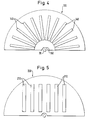
- trolleys 200 in which the trays 210 are arranged parallel to one another, although here the space available in the cleaning device according to FIG. 1 is not fully utilized.
Landscapes
- Engineering & Computer Science (AREA)
- Mechanical Engineering (AREA)
- Cleaning By Liquid Or Steam (AREA)
Applications Claiming Priority (2)
| Application Number | Priority Date | Filing Date | Title |
|---|---|---|---|
| DE4215614A DE4215614A1 (de) | 1992-05-12 | 1992-05-12 | Vorrichtung und Verfahren zum Reinigen von Wagen zum Transport von Speisetabletts oder dergleichen sowie Wagen hierfür |
| DE4215614 | 1992-05-12 |
Publications (3)
| Publication Number | Publication Date |
|---|---|
| EP0569885A2 true EP0569885A2 (fr) | 1993-11-18 |
| EP0569885A3 EP0569885A3 (en) | 1993-12-22 |
| EP0569885B1 EP0569885B1 (fr) | 1996-09-18 |
Family
ID=6458672
Family Applications (1)
| Application Number | Title | Priority Date | Filing Date |
|---|---|---|---|
| EP93107480A Expired - Lifetime EP0569885B1 (fr) | 1992-05-12 | 1993-05-07 | Dispositif et procédé pour nettoyer un chariot pour le transport des plateaux d'alimentation ou similaires et chariot approprié |
Country Status (2)
| Country | Link |
|---|---|
| EP (1) | EP0569885B1 (fr) |
| DE (2) | DE4215614A1 (fr) |
Cited By (7)
| Publication number | Priority date | Publication date | Assignee | Title |
|---|---|---|---|---|
| EP0770432A3 (fr) * | 1995-10-26 | 1998-01-21 | Pötzscher, Carola | Machine à laver |
| NL1007094C2 (nl) * | 1997-09-22 | 1999-03-23 | Numafa Holding B V | Inrichting en werkwijze voor het reinigen van cateringswagens. |
| EP0820718A3 (fr) * | 1996-07-26 | 1999-04-21 | Sharp Kabushiki Kaisha | Lave vaisselle pour laver les assiettes à panier de lavage tournant et panier de lavage correspondant |
| ITTO20090502A1 (it) * | 2009-07-03 | 2011-01-04 | Biemmedue S P A | Metodo e macchina di lavaggio per un contenitore di forma parallelepipeda |
| EP3546076A3 (fr) * | 2018-03-05 | 2019-10-23 | Nicola Papa | Machine de désinfection pour chariots de supermarchés |
| CN113978425A (zh) * | 2021-10-25 | 2022-01-28 | 浙江铁士机械有限公司 | 一种具备多角度调节功能的智能洗车机及其使用方法 |
| WO2022031204A1 (fr) * | 2020-08-05 | 2022-02-10 | SanArK Systems AB | Agencement de désinfection et procédé de désinfection |
Families Citing this family (5)
| Publication number | Priority date | Publication date | Assignee | Title |
|---|---|---|---|---|
| DK173019B1 (da) * | 1996-04-24 | 1999-11-15 | Ken Maskinfabrik As | Anordning til afvaskning, skylning og tørring af genstande, såsom cateringvogne til anvendelse om bord på flyvemaskiner |
| DE19639123C1 (de) * | 1996-09-24 | 1997-11-20 | Daimler Benz Aerospace Airbus | Vorrichtung zur Reinigung von Geschirr für ein Verpflegungssystem in einem Flugzeug |
| DK173400B1 (da) | 1998-04-30 | 2000-09-25 | Ken Maskinfabrik As | Anlæg og fremgangsmåde til fremføring og rengøring af transportvogne |
| DE202009009982U1 (de) | 2009-07-03 | 2009-10-01 | Guggenberger Reinigungstechnik E.K. | Vorrichtung zum Reinigen von Waschgut |
| EP4357036A1 (fr) * | 2022-10-19 | 2024-04-24 | Dinox SL | Machine à laver les transpalettes |
Family Cites Families (7)
| Publication number | Priority date | Publication date | Assignee | Title |
|---|---|---|---|---|
| US3517675A (en) * | 1967-10-30 | 1970-06-30 | Ind Washing Machine Corp | Apparatus for washing industrial articles |
| US3736948A (en) * | 1971-07-28 | 1973-06-05 | B Crosswhite | Washing and sanitizing apparatus for carts such as hospital carts |
| US4408625A (en) * | 1982-05-07 | 1983-10-11 | Kuhl Henry Y | Article washing means with movable spray heads |
| US4452263A (en) * | 1982-06-28 | 1984-06-05 | Mcclure Plastics Company Incorporated | Cart washing and sanitizing apparatus |
| US4744379A (en) * | 1986-02-20 | 1988-05-17 | Goettel Andrew P | Conveyor system for washing apparatus |
| DE3828035C2 (de) * | 1988-08-18 | 1998-07-02 | Hobart Corp N D Ges Des Staate | Maschinen zum Reinigen von Servierwagen und dergleichen |
| US4941491A (en) * | 1989-04-07 | 1990-07-17 | Automated Cleaning Systems, Inc. | Method and apparatus for cleaning containers |
-
1992
- 1992-05-12 DE DE4215614A patent/DE4215614A1/de not_active Withdrawn
-
1993
- 1993-05-07 DE DE59303815T patent/DE59303815D1/de not_active Expired - Fee Related
- 1993-05-07 EP EP93107480A patent/EP0569885B1/fr not_active Expired - Lifetime
Cited By (7)
| Publication number | Priority date | Publication date | Assignee | Title |
|---|---|---|---|---|
| EP0770432A3 (fr) * | 1995-10-26 | 1998-01-21 | Pötzscher, Carola | Machine à laver |
| EP0820718A3 (fr) * | 1996-07-26 | 1999-04-21 | Sharp Kabushiki Kaisha | Lave vaisselle pour laver les assiettes à panier de lavage tournant et panier de lavage correspondant |
| NL1007094C2 (nl) * | 1997-09-22 | 1999-03-23 | Numafa Holding B V | Inrichting en werkwijze voor het reinigen van cateringswagens. |
| ITTO20090502A1 (it) * | 2009-07-03 | 2011-01-04 | Biemmedue S P A | Metodo e macchina di lavaggio per un contenitore di forma parallelepipeda |
| EP3546076A3 (fr) * | 2018-03-05 | 2019-10-23 | Nicola Papa | Machine de désinfection pour chariots de supermarchés |
| WO2022031204A1 (fr) * | 2020-08-05 | 2022-02-10 | SanArK Systems AB | Agencement de désinfection et procédé de désinfection |
| CN113978425A (zh) * | 2021-10-25 | 2022-01-28 | 浙江铁士机械有限公司 | 一种具备多角度调节功能的智能洗车机及其使用方法 |
Also Published As
| Publication number | Publication date |
|---|---|
| DE59303815D1 (de) | 1996-10-24 |
| EP0569885A3 (en) | 1993-12-22 |
| DE4215614A1 (de) | 1993-11-18 |
| EP0569885B1 (fr) | 1996-09-18 |
Similar Documents
| Publication | Publication Date | Title |
|---|---|---|
| EP0569885B1 (fr) | Dispositif et procédé pour nettoyer un chariot pour le transport des plateaux d'alimentation ou similaires et chariot approprié | |
| EP0956163B1 (fr) | Installation de nettoyage industriel | |
| DE3300666C2 (de) | Waschverfahren für metallhaltige und nicht-metallhaltige Teile wie Kleinteile, mechanische Komponenten und Teile für die elektronische Industrie sowie eine Maschine zur Durchführung dieses Verfahrens | |
| DE1935139U (de) | Spuelvorrichtung, insbesondere zum spuelen von besteck. | |
| DE102004003797A1 (de) | Geschirrspülautomat mit regelbarer Wärmrückgewinnung | |
| DE19509645B4 (de) | Waschanlage zum Reinigen von Gegenständen | |
| DE4244880C2 (de) | Vorrichtung zum Waschen und Trocknen von mehreren Transportkästen | |
| EP0836532B1 (fr) | Dispositif et procede pour nettoyer des pistolets taches pas de la peinture | |
| WO1994010895A1 (fr) | Lave-vaisselle | |
| DE102004062137B3 (de) | Verfahren und Vorrichtung zum Reinigen einer Überziehmaschine | |
| DE69207915T2 (de) | Gerät zum entfetten von gegenständen | |
| DE2161446B1 (de) | Kontinuierlich arbeitende Wasch und Trockenmaschine fur Kleinteile | |
| EP3165286A1 (fr) | Procédé et appareil pour déshuiler et/ou nettoyer des articles de série | |
| DE3828035A1 (de) | Verfahren zum reinigen von servierwagen und dergleichen und vorrichtung | |
| DE102010025846B4 (de) | Vorrichtung zum Reinigen von Waschgut | |
| DE3515829A1 (de) | Verfahren zur reinigung von auf foerderbahnen fortbewegten werkstuecktraegern und waschgeraet zur durchfuehrung des verfahrens | |
| DE9219151U1 (de) | Vorrichtung zum Reinigen von Wagen zum Transport von Speisetabletts o.dgl. sowie Wagen hierfür | |
| DE2615976A1 (de) | Vorrichtung zum trocknen des aus einer geschirrspuelvorrichtung kommenden geschirrs | |
| DE19620400C2 (de) | Verfahren und Vorrichtung zum Waschen von Fahrzeugen | |
| DE2806126A1 (de) | Reinigungsvorrichtung | |
| DE19704989A1 (de) | Vorrichtung und Verfahren zum Reinigen von Kasserollen | |
| DE4443583C2 (de) | Verfahren und Vorrichtung zum Reinigen und/oder Trocknen von Werkstücken | |
| DE19950199B4 (de) | Reinigungsstation zum Besprühen und/oder Spülen von Fahrzeugkarosserien und Verfahren zum Reinigen von Fahrzeugkarosserien | |
| DE2248220A1 (de) | Flaschenreinigungsmaschine | |
| DE19602374A1 (de) | Transporteinrichtung |
Legal Events
| Date | Code | Title | Description |
|---|---|---|---|
| PUAI | Public reference made under article 153(3) epc to a published international application that has entered the european phase |
Free format text: ORIGINAL CODE: 0009012 |
|
| PUAL | Search report despatched |
Free format text: ORIGINAL CODE: 0009013 |
|
| AK | Designated contracting states |
Kind code of ref document: A2 Designated state(s): CH DE FR GB IT LI SE |
|
| AK | Designated contracting states |
Kind code of ref document: A3 Designated state(s): CH DE FR GB IT LI SE |
|
| 17P | Request for examination filed |
Effective date: 19940208 |
|
| 17Q | First examination report despatched |
Effective date: 19941222 |
|
| GRAG | Despatch of communication of intention to grant |
Free format text: ORIGINAL CODE: EPIDOS AGRA |
|
| GRAH | Despatch of communication of intention to grant a patent |
Free format text: ORIGINAL CODE: EPIDOS IGRA |
|
| GRAA | (expected) grant |
Free format text: ORIGINAL CODE: 0009210 |
|
| GRAH | Despatch of communication of intention to grant a patent |
Free format text: ORIGINAL CODE: EPIDOS IGRA |
|
| AK | Designated contracting states |
Kind code of ref document: B1 Designated state(s): CH DE FR GB IT LI SE |
|
| REG | Reference to a national code |
Ref country code: CH Ref legal event code: NV Representative=s name: BUECHEL & PARTNER AG PATENTBUERO |
|
| GBT | Gb: translation of ep patent filed (gb section 77(6)(a)/1977) |
Effective date: 19960927 |
|
| ITF | It: translation for a ep patent filed | ||
| REF | Corresponds to: |
Ref document number: 59303815 Country of ref document: DE Date of ref document: 19961024 |
|
| ET | Fr: translation filed | ||
| PLBE | No opposition filed within time limit |
Free format text: ORIGINAL CODE: 0009261 |
|
| 26N | No opposition filed | ||
| REG | Reference to a national code |
Ref country code: GB Ref legal event code: 732E |
|
| REG | Reference to a national code |
Ref country code: CH Ref legal event code: PUE Owner name: PREMARK FEG CORPORATION TRANSFER- PREMARK FEG L.L. |
|
| REG | Reference to a national code |
Ref country code: FR Ref legal event code: TP |
|
| PGFP | Annual fee paid to national office [announced via postgrant information from national office to epo] |
Ref country code: FR Payment date: 20010418 Year of fee payment: 9 |
|
| PGFP | Annual fee paid to national office [announced via postgrant information from national office to epo] |
Ref country code: DE Payment date: 20010419 Year of fee payment: 9 |
|
| PGFP | Annual fee paid to national office [announced via postgrant information from national office to epo] |
Ref country code: SE Payment date: 20010420 Year of fee payment: 9 Ref country code: GB Payment date: 20010420 Year of fee payment: 9 Ref country code: CH Payment date: 20010420 Year of fee payment: 9 |
|
| REG | Reference to a national code |
Ref country code: GB Ref legal event code: IF02 |
|
| PG25 | Lapsed in a contracting state [announced via postgrant information from national office to epo] |
Ref country code: GB Free format text: LAPSE BECAUSE OF NON-PAYMENT OF DUE FEES Effective date: 20020507 |
|
| PG25 | Lapsed in a contracting state [announced via postgrant information from national office to epo] |
Ref country code: SE Free format text: LAPSE BECAUSE OF NON-PAYMENT OF DUE FEES Effective date: 20020508 |
|
| PG25 | Lapsed in a contracting state [announced via postgrant information from national office to epo] |
Ref country code: LI Free format text: LAPSE BECAUSE OF NON-PAYMENT OF DUE FEES Effective date: 20020531 Ref country code: CH Free format text: LAPSE BECAUSE OF NON-PAYMENT OF DUE FEES Effective date: 20020531 |
|
| PG25 | Lapsed in a contracting state [announced via postgrant information from national office to epo] |
Ref country code: DE Free format text: LAPSE BECAUSE OF NON-PAYMENT OF DUE FEES Effective date: 20021203 |
|
| GBPC | Gb: european patent ceased through non-payment of renewal fee |
Effective date: 20020507 |
|
| EUG | Se: european patent has lapsed | ||
| REG | Reference to a national code |
Ref country code: CH Ref legal event code: PL |
|
| PG25 | Lapsed in a contracting state [announced via postgrant information from national office to epo] |
Ref country code: FR Free format text: LAPSE BECAUSE OF NON-PAYMENT OF DUE FEES Effective date: 20030131 |
|
| REG | Reference to a national code |
Ref country code: FR Ref legal event code: ST |
|
| PG25 | Lapsed in a contracting state [announced via postgrant information from national office to epo] |
Ref country code: IT Free format text: LAPSE BECAUSE OF NON-PAYMENT OF DUE FEES;WARNING: LAPSES OF ITALIAN PATENTS WITH EFFECTIVE DATE BEFORE 2007 MAY HAVE OCCURRED AT ANY TIME BEFORE 2007. THE CORRECT EFFECTIVE DATE MAY BE DIFFERENT FROM THE ONE RECORDED. Effective date: 20050507 |