EP0569932B1 - Armatur mit isolierendem Zwischenstück - Google Patents
Armatur mit isolierendem Zwischenstück Download PDFInfo
- Publication number
- EP0569932B1 EP0569932B1 EP93107642A EP93107642A EP0569932B1 EP 0569932 B1 EP0569932 B1 EP 0569932B1 EP 93107642 A EP93107642 A EP 93107642A EP 93107642 A EP93107642 A EP 93107642A EP 0569932 B1 EP0569932 B1 EP 0569932B1
- Authority
- EP
- European Patent Office
- Prior art keywords
- intermediate piece
- fitting
- insulation
- housing
- valve
- Prior art date
- Legal status (The legal status is an assumption and is not a legal conclusion. Google has not performed a legal analysis and makes no representation as to the accuracy of the status listed.)
- Expired - Lifetime
Links
Images
Classifications
-
- F—MECHANICAL ENGINEERING; LIGHTING; HEATING; WEAPONS; BLASTING
- F16—ENGINEERING ELEMENTS AND UNITS; GENERAL MEASURES FOR PRODUCING AND MAINTAINING EFFECTIVE FUNCTIONING OF MACHINES OR INSTALLATIONS; THERMAL INSULATION IN GENERAL
- F16L—PIPES; JOINTS OR FITTINGS FOR PIPES; SUPPORTS FOR PIPES, CABLES OR PROTECTIVE TUBING; MEANS FOR THERMAL INSULATION IN GENERAL
- F16L59/00—Thermal insulation in general
- F16L59/14—Arrangements for the insulation of pipes or pipe systems
- F16L59/16—Arrangements specially adapted to local requirements at flanges, junctions, valves or the like
-
- E—FIXED CONSTRUCTIONS
- E03—WATER SUPPLY; SEWERAGE
- E03C—DOMESTIC PLUMBING INSTALLATIONS FOR FRESH WATER OR WASTE WATER; SINKS
- E03C1/00—Domestic plumbing installations for fresh water or waste water; Sinks
- E03C1/02—Plumbing installations for fresh water
Definitions
- the air conditioning systems of buildings generally include hot water generators and cold water generators, which enable the supply or removal of heat from rooms in buildings via a distributor and a pipe system.
- the heat transfer flow is usually regulated with fittings.
- these systems are insulated as well as possible.
- the heating system regulation only prescribes a certain thickness of insulation, but the design of the insulation depends on the design of the individual fittings.
- the water vapor contained in air condenses out at the cold points of the piping system. These places are often poorly insulated components, especially fittings. The condensate increases the risk of corrosion of the valve as well as the environment and then quickly calls one for the aesthetic An unpleasant impression of a deteriorated state of the system.
- the visual impression is a criterion that should not be underestimated for assessing the overall system for fittings that are visible to everyone.
- DE-B-1 551 591 and DE-U-89 10 705 disclose a fitting consisting of a housing with a flow opening, a shut-off body and an actuating mechanism for actuating the shut-off body, which has a neck on its housing in which a transmission element is guided , With an end flange, an intermediate piece being attached to the end flange.
- the internal state of the art is formed by butterfly valves, which have an intermediate plate made of thermally insulating material on their end flange of the upper part of the valve, through which the shaft passes and then the actuator is connected to the shaft (brochure "Butterfly valve BOAX-II").
- the intermediate plate is firmly connected to the end flange of the housing. In order to isolate this fitting, the insulation is brought up to the intermediate plate and sealed in a complex manner. The adjustment of the insulation is done by hand for each fitting individually.
- the problem to be solved with the invention is that with the previously known fittings, full insulation is very difficult.
- the invention has for its object to provide a fitting in which full insulation is easily possible.
- the advantage over the prior art is that in the cavities of the intermediate piece made of a material with low thermal conductivity, the air as an insulator increases the insulating effect and with the extension of the Intermediate piece in the form of an apron over the end flange the insulation can be attached both above and below the end flange.
- the intermediate piece extends at least so far that thermal insulation of the fitting housing in the area of the neck is possible without problems on the intermediate piece.
- the usual sealing of the insulation on the intermediate piece also prevents the exchange of air between the air in the insulation and the ambient air.
- the intermediate piece can be standardized by standardizing its outer dimensions. Isolation can be simplified by standardizing and using prefabricated products, and there is no need for time-consuming manual adjustments.
- the connection point of the insulation to the neck comes so far from the valve body that the actuating device can be used without hindrance even when the valve is completely isolated.
- the intermediate piece can be used for fittings with a straight line or with a rotating or oscillating movement of the closing body.
- the development according to claim 2 has the advantage that complete encapsulation of the connection point of the actuating device is achieved except for a gap.
- the ring element is supported on the intermediate piece and leaves only a gap open there as well.
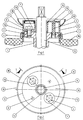
- An end flange (2) on the neck (1) of a fitting which has bores (3, 4).
- a shaft (5) or a spindle for actuating the shut-off body is guided through the neck (1).
- An intermediate piece (6) made of thermally insulating material sits on the end flange (2).
- the intermediate piece (6) is connected to the end flange (2) by screws (7) and secured against rotation by centering aids (8) which engage in the opening (3) of the end flange (2).
- the centering aids (8) are distributed over the circumference between the screws (7) and supported by ribs, not shown.
- the outer jacket (9) of the intermediate piece is extended like an apron over the end flange (2) towards the housing. In another direction, it extends away from the end flange (2) and encloses a cavity (11) between a cover plate (10) and the end flange (2).
- the cavity (11) is interrupted where the screw (7) is arranged.
- the intermediate piece (6) is shaped at this point in such a way that a bearing surface (12) is created between the screw (7) and the end flange (2).
- the opening for the screw (7) can be closed with a plug (13).
- the intermediate piece (6) has a passage opening for the shaft (5) on the inner casing (14) and encloses the shaft (5) while maintaining an air gap.
- a device for acting on the shaft, a lever, a handwheel or the like is placed on the shaft (5).
- the insulation (15) can be connected and sealed directly to the outer lateral surface (9). This completely isolates the valve body.
- a projecting ring element (16) can be attached to the intermediate piece to isolate the connection point between the actuating device and the intermediate piece.
- the ring element is supported on the outer casing (9) by a circumferential projection (17).
- the surface (18) of the ring element forms a kind of seal with a corresponding surface of the actuating device.
- the shaft (5) can be thermally decoupled from the actuating device via a coupling made of material with low thermal conductivity. For valves with rising stem, further measures are necessary to isolate them.
Landscapes
- Engineering & Computer Science (AREA)
- General Engineering & Computer Science (AREA)
- Mechanical Engineering (AREA)
- Health & Medical Sciences (AREA)
- Life Sciences & Earth Sciences (AREA)
- Hydrology & Water Resources (AREA)
- Public Health (AREA)
- Water Supply & Treatment (AREA)
- Insulating Bodies (AREA)
- Resistance Heating (AREA)
- Insulators (AREA)
- Valve Housings (AREA)
- Mechanically-Actuated Valves (AREA)
- Details Of Valves (AREA)
- Thermal Insulation (AREA)
- Threshing Machine Elements (AREA)
Description
- Die Klimaanlagen von Gebäuden umfassen in der Regel Heißwassererzeuger und Kaltwassererzeuger, welche über einen Verteiler und ein Rohrleitungssystem die Zu- oder Abfuhr von Wärme aus Räumen von Gebäuden ermöglichen. Der Wärmeträgerstrom wird üblicherweise mit Armaturen geregelt. Um einen Energieverlust oder eine Auskondensation der in der Luft enthaltenen Feuchtigkeit an den kalten Stellen im Rohrleitungssystem zu vermeiden, sind diese Anlagen so gut wie möglich isoliert.
- Für Rohrleitungssysteme ist eine Isolation weitgehend in Normen festgeschrieben und mit standardisierten Produkten durchzuführen. Was hingegen die zusätzlichen Teile wie Armaturen betrifft, welche in Form und Abmessung sehr stark voneinander abweichen, ist die Isolation sehr aufwendig. Bei Heiz- und Kühlkreisläufen ist daher der Gehäusehals der Armatur, an welchen üblicherweise ein Stellmechanismus über ein Übertragungselement auf den Absperrkörper der Armatur einwirkt, in der Regel nur teilweise isoliert und er ragt über die Isolation hinaus.
- Für den Heizungskreislauf ist in der Heizungsanlagenverordnung lediglich eine bestimmte Stärke der Isolation vorgeschrieben, die Ausführung der Isolierung richtet sich aber nach den Bauformen der einzelnen Armaturen. Im Kühlkreislauf kondensiert der in Luft enthaltene Wasserdampf an den kalten Stellen des Rohrleitungssystems aus. Diese Stellen sind oftmals mangelhaft isolierte Bauteile, insbesondere Armaturen. Das Kondensat erhöht die Korrosionsgefahr der Armatur wie auch der Umgebung und ruft dann schnell einen für den ästhetischen Eindruck unangenehmen Eindruck eines verfallenen Zustandes der Anlage hervor. Der optische Eindruck ist aber bei für jedermann sichtbaren Armaturen ein nicht zu unterschätzendes Kriterium für die Beurteilung der Gesamtanlage.
- Als Folgen einer mangelhaften Isolation des Rohrleitungssystems ergeben sich daher eine Erhöhung der Betriebskosten durch Energieverluste und höheren Wartungsaufwand sowie eine schnelle Verschlechterung des optischen Eindrucks bei den Armaturen.
- DE-B- 1 551 591 und DE-U- 89 10 705 offenbaren eine Armatur, bestehend aus einem Gehäuse mit einer Durchflußöffnung, einem Absperrkörper und einem Stellmechanismus zur Betätigung des Absperrkörpers, welche an ihrem Gehäuse einen Hals, in welchem ein Übertragungselement geführt ist, mit Endflansch aufweist, wobei an dem Endflansch ein Zwischenstück angebracht ist.
- Der innerbetriebliche Stand der Technik wird durch Absperrklappen gebildet, welche an ihrem Endflansch des Oberteils der Armatur eine Zwischenplatte aus thermisch isolierendem Material aufweisen, durch welche die Welle hindurchgeht und anschließend die Betätigungsvorrichtung mit der Welle verbunden wird (Prospekt "Absperrklappe BOAX-II"). Die Zwischenplatte ist fest mit dem Endflansch des Gehäuses verbunden. Um diese Armatur zu isolieren, wird die Isolation an die Zwischenplatte herangeführt und aufwendig abgedichtet. Die Anpassung der Isolation geschieht in aufwendiger Handarbeit für jede Armatur einzeln.
- Das mit der Erfindung zu lösende Problem liegt darin, daß bei den bislang bekannten Armaturen eine Vollisolation nur sehr schwierig möglich ist. Der Erfindung liegt die Aufgabe zugrunde, eine Armatur zu schaffen, bei welcher eine Vollisolation einfach möglich ist.
- Das Problem wird durch die in Anspruch 1 angegebene Lehre gelöst.
- Der Vorteil gegenüber dem Stand der Technik besteht darin, daß in den Hohlräumen des Zwischenstückes aus einem Material geringer Wärmeleitfähigkeit die Luft als Isolator die Isolationswirkung erhöht und mit der Erstreckung des Zwischenstücks in Form einer Schürze über den Endflansch die Isolation sowohl oberhalb als auch unterhalb des Endflansches angebracht werden kann. Das Zwischenstück erstreckt sich mindestens so weit, daß eine thermische Isolation des Armaturengehäuses im Bereich des Halses problemlos am Zwischenstück möglich ist. Durch die übliche Abdichtung der Isolation an dem Zwischenstück wird auch der Luftaustausch von der in der Isolation befindlichen Luft und der Umgebungsluft verhindert.
- Dank der erhöhten Isolationswirkung wird die Kondensation von Wasserdampf an dem Zwischenstück verhindert. Es bilden sich keine Rinnsale aus Kondensat, welche den ästhetischen Eindruck der Anlage durch Korrosionserscheinungen beeinträchtigen. Das Zwischenstück kann durch Normung seiner Außenabmessungen vereinheitlicht werden. Die Isolation kann durch die Standardisierung und Verwendung vorgefertigter Produkte vereinfacht werden und eine aufwendige Handanpassung entfällt. Die Anschlußstelle der Isolation an den Hals kommt so weit von dem Armaturengehäuse zu liegen, daß eine Benutzung der Betätigungsvorrichtung ohne Behinderung auch bei vollständiger Isolation der Armatur möglich ist.
- Das Zwischenstück kann für Armaturen mit geradliniger oder mit drehender bzw. schwingender Bewegung des Abschlußkörpers verwendet werden.
- Die Weiterbildung nach Anspruch 2 hat den Vorteil, daß eine bis auf einen Spalt vollständige Kapselung der Anschlußstelle der Betätigungsvorrichtung erreicht wird. Das Ringelement stützt sich am Zwischenstück ab und läßt auch dort nur einen Spalt offen.
- Ein Ausführungsbeispiel der Erfindung ist in der Zeichnung dargestellt und wird im folgenden näher beschrieben. Es zeigt die
- Fig. 1
- das Zwischenstück im Längsschnitt I-I
- Fig. 2
- das Zwischenstück in der Draufsicht.
- An dem Hals (1) einer Armatur befindet sich ein Endflansch (2), welcher Bohrungen (3, 4) aufweist. Durch den Hals (1) wird eine Welle (5) oder eine Spindel zur Betätigung des Absperrkörpers geführt. Auf dem Endflansch (2) sitzt ein Zwischenstück (6) aus thermisch isolierendem Material. Das Zwischenstück (6) ist durch Schrauben (7) mit dem Endflansch (2) verbunden und durch Zentrierhilfen (8), welche in die Öffnung (3) des Endflansches (2) eingreift, gegen Verdrehung gesichert. Die Zentrierhilfen (8) sind über dem Umfang verteilt zwischen den Schrauben (7) angeordnet und über nicht dargestellte Rippen abgestützt.
- Der äußere Mantel (9) des Zwischenstückes ist über den Endflansch (2) in Richtung Gehäuse schürzenartig verlängert. In anderer Richtung erstreckt es sich vom Endflansch (2) weg und schließt zwischen einer Deckscheibe (10) und dem Endflansch (2) einen Hohlraum (11) ein. Der Hohlraum (11) ist dort unterbrochen, wo die Schraube (7) angeordnet ist. Das Zwischenstück (6) ist an dieser Stelle so geformt, daß eine Auflagefläche (12) zwischen der Schraube (7) und dem Endflansch (2) entsteht. Mit einem Stopfen (13) kann die Öffnung für die Schraube (7) verschlossen werden.
- Das Zwischenstück (6) weist an dem inneren Mantel (14) eine Durchlaßöffnung für die Welle (5) auf und umschließt die Welle (5) unter Beibehaltung eines Luftspaltes. Auf die Welle (5) wird eine Vorrichtung zum Einwirken auf die Welle, ein Hebel, ein Handrad oder ähnliches, gesetzt. An die äußere Mantelfläche (9) kann direkt die Isolation (15) angeschlossen und abgedichtet werden. Damit ist das Gehäuse der Absperrarmatur vollständig isoliert.
- Zur Isolation der Verbindungsstelle Betätigungsvorrichtung / Zwischenstück kann ein vorstehendes Ringelement (16) am Zwischenstück angebracht werden. Das Ringelement wird über einen umlaufenden Vorsprung (17) am äußeren Mantel (9) abgestützt. Die Fläche (18) des Ringelementes bildet eine Art Dichtung mit einer entsprechenden Fläche der Betätigungsvorrichtung.
- Die Welle (5) kann zu ihrer Isolation von der Betätigungsvorrichtung über eine Kupplung aus Material geringer Wärmeleitfähigkeit thermisch entkoppelt werden. Bei Armaturen mit steigender Spindel sind zu deren Isolation weitere Maßnahmen notwendig.
Claims (2)
- Armatur, bestehend aus einem Gehäuse mit einer Durchflußöffnung, einem Absperrkörper und einem Stellmechanismus zur Betätigung des Absperrkörpers, welche an ihrem Gehäuse einen Hals (1), in welchem ein Übertragungselement (5) geführt ist, mit Endflansch (2) aufweist, wobei an dem Endflansch (2) ein Zwischenstück (6) aus einem Material geringer Wärmeleitfähigkeit angebracht ist, dadurch gekennzeichnet, daß das Zwischenstück (6) den Endflansch (2) mit seinem äußeren Mantel (9) schürzenartig in Richtung zur Durchflußöffnung umhüllt, wobei es sich zudem vom Gehäuse weg erstreckt und einen Hohlraum (11) aufweist, welcher von dem äußeren Mantel (9), einem das Übertragungselement (5) umhüllenden inneren Mantel (14), einer Deckscheibe (10) zur Verbindung dieser beiden Mäntel (9, 14) und der Oberseite des Endflansches (2) gebildet wird.
- Armatur nach Anspruch 1, dadurch gekennzeichnet, daß die Armatur eine Betätigungsvorrichtung zur Einwirkung auf das Übertragungselement (5) aufweist, daß am Zwischenstück (6) ein vorstehendes Ringelement (16) angebracht wird und daß die Betätigungsvorrichtung mit einer Fläche zum Anschluß an die Fläche (18) des Ringelementes (16) versehen ist.
Applications Claiming Priority (2)
| Application Number | Priority Date | Filing Date | Title |
|---|---|---|---|
| DE4215407 | 1992-05-11 | ||
| DE4215407A DE4215407C2 (de) | 1992-05-11 | 1992-05-11 | Armatur mit isolierendem Zwischenstück |
Publications (3)
| Publication Number | Publication Date |
|---|---|
| EP0569932A2 EP0569932A2 (de) | 1993-11-18 |
| EP0569932A3 EP0569932A3 (de) | 1994-10-26 |
| EP0569932B1 true EP0569932B1 (de) | 1995-11-15 |
Family
ID=6458550
Family Applications (1)
| Application Number | Title | Priority Date | Filing Date |
|---|---|---|---|
| EP93107642A Expired - Lifetime EP0569932B1 (de) | 1992-05-11 | 1993-05-11 | Armatur mit isolierendem Zwischenstück |
Country Status (4)
| Country | Link |
|---|---|
| EP (1) | EP0569932B1 (de) |
| AT (1) | ATE130420T1 (de) |
| DE (2) | DE4215407C2 (de) |
| ES (1) | ES2082550T3 (de) |
Families Citing this family (1)
| Publication number | Priority date | Publication date | Assignee | Title |
|---|---|---|---|---|
| DE10004259C2 (de) * | 2000-02-02 | 2001-11-29 | Ksb Ag | Isolierstück |
Family Cites Families (5)
| Publication number | Priority date | Publication date | Assignee | Title |
|---|---|---|---|---|
| DE1929027A1 (de) * | 1969-06-07 | 1970-12-10 | Siemens Ag | Waermeisolierung von Maschinenteilen,insbesondere in Kernreaktoren |
| JPS6051364U (ja) * | 1983-09-19 | 1985-04-11 | 旭有機材工業株式会社 | ゲ−トバルブ |
| DE3832627C2 (de) * | 1988-09-26 | 1993-12-02 | Willich F Gmbh & Co | Absperrventil für isolierte Rohrleitungen |
| DE8910705U1 (de) * | 1989-09-08 | 1990-01-18 | Eisenwerk Heinrich Schilling Gmbh & Co, 4800 Bielefeld | Schieber als Armatur für Flüssigkeiten o.dgl. |
| DE4027460A1 (de) * | 1990-08-30 | 1992-03-12 | Richter Albert Ari Armaturen | Armatur |
-
1992
- 1992-05-11 DE DE4215407A patent/DE4215407C2/de not_active Expired - Fee Related
-
1993
- 1993-05-11 DE DE59300932T patent/DE59300932D1/de not_active Expired - Lifetime
- 1993-05-11 EP EP93107642A patent/EP0569932B1/de not_active Expired - Lifetime
- 1993-05-11 AT AT93107642T patent/ATE130420T1/de not_active IP Right Cessation
- 1993-05-11 ES ES93107642T patent/ES2082550T3/es not_active Expired - Lifetime
Also Published As
| Publication number | Publication date |
|---|---|
| DE4215407A1 (de) | 1993-11-18 |
| EP0569932A3 (de) | 1994-10-26 |
| DE4215407C2 (de) | 1996-07-18 |
| ES2082550T3 (es) | 1996-03-16 |
| EP0569932A2 (de) | 1993-11-18 |
| DE59300932D1 (de) | 1995-12-21 |
| ATE130420T1 (de) | 1995-12-15 |
Similar Documents
| Publication | Publication Date | Title |
|---|---|---|
| DE10126967B4 (de) | Öffnungs-/Schließventil | |
| DE2854943C2 (de) | Heizvorrichtung mit Schutzgassystem | |
| DE102005040699B3 (de) | Temperaturmessvorrichtung | |
| DE2105583A1 (de) | Magnetventil zur Abgasrückführung bei Brennkraftmaschinen | |
| DE4215407C2 (de) | Armatur mit isolierendem Zwischenstück | |
| DE2448383C2 (de) | Temperaturgesteuertes Ventil | |
| EP0309678B1 (de) | Verfahren zum Fertigen eines Kugelkükens für einen Kugelhahn | |
| DE2155376A1 (de) | Einrichtung zur Regelung der Tempera tür eines Raumes | |
| EP1018063B1 (de) | Regler | |
| EP0059905B2 (de) | Sicherheitsventil | |
| DE9218557U1 (de) | Armatur mit isolierendem Zwischenstück | |
| DE2428895A1 (de) | Abschliessende luftauslassvorrichtung | |
| DE19854848B4 (de) | Anschlusseinrichtung für Heizkörper | |
| DE102007005766B4 (de) | Heizkörperanordnung | |
| DE3011045A1 (de) | Elektrode | |
| DE3527738C2 (de) | Klappenventil | |
| EP1239238A1 (de) | Anschlussarmatur für einen Heizkörper | |
| DE3116502A1 (de) | "bausatz zum umruesten von zweigriff-unterputzarmaturen" | |
| DE19944365B4 (de) | Ventil, insbesondere Heizkörperventil | |
| DE7916786U1 (de) | Elektrisch beheizter heisswasser-durchlauferhitzer | |
| DE102010055483B4 (de) | Ventil, insbesondere Heizkörperventil | |
| EP1656518A1 (de) | Modulares ventil- und verteilersystem | |
| DE971792C (de) | Hahn, insbesondere Milchhahn | |
| DE19535214C2 (de) | Gasentnahmesonde | |
| CH698702B1 (de) | Ventil. |
Legal Events
| Date | Code | Title | Description |
|---|---|---|---|
| PUAI | Public reference made under article 153(3) epc to a published international application that has entered the european phase |
Free format text: ORIGINAL CODE: 0009012 |
|
| AK | Designated contracting states |
Kind code of ref document: A2 Designated state(s): AT BE CH DE DK ES FR GB IT LI LU NL SE |
|
| PUAL | Search report despatched |
Free format text: ORIGINAL CODE: 0009013 |
|
| AK | Designated contracting states |
Kind code of ref document: A3 Designated state(s): AT BE CH DE DK ES FR GB IT LI LU NL SE |
|
| 17P | Request for examination filed |
Effective date: 19941110 |
|
| 17Q | First examination report despatched |
Effective date: 19950405 |
|
| GRAA | (expected) grant |
Free format text: ORIGINAL CODE: 0009210 |
|
| AK | Designated contracting states |
Kind code of ref document: B1 Designated state(s): AT BE CH DE DK ES FR GB IT LI LU NL SE |
|
| PG25 | Lapsed in a contracting state [announced via postgrant information from national office to epo] |
Ref country code: DK Effective date: 19951115 |
|
| REF | Corresponds to: |
Ref document number: 130420 Country of ref document: AT Date of ref document: 19951215 Kind code of ref document: T |
|
| REF | Corresponds to: |
Ref document number: 59300932 Country of ref document: DE Date of ref document: 19951221 |
|
| ITF | It: translation for a ep patent filed | ||
| PG25 | Lapsed in a contracting state [announced via postgrant information from national office to epo] |
Ref country code: SE Effective date: 19960215 |
|
| REG | Reference to a national code |
Ref country code: ES Ref legal event code: FG2A Ref document number: 2082550 Country of ref document: ES Kind code of ref document: T3 |
|
| ET | Fr: translation filed | ||
| GBT | Gb: translation of ep patent filed (gb section 77(6)(a)/1977) |
Effective date: 19960223 |
|
| PG25 | Lapsed in a contracting state [announced via postgrant information from national office to epo] |
Ref country code: AT Effective date: 19960511 |
|
| PG25 | Lapsed in a contracting state [announced via postgrant information from national office to epo] |
Ref country code: LU Free format text: LAPSE BECAUSE OF NON-PAYMENT OF DUE FEES Effective date: 19960531 |
|
| PLBQ | Unpublished change to opponent data |
Free format text: ORIGINAL CODE: EPIDOS OPPO |
|
| PLBI | Opposition filed |
Free format text: ORIGINAL CODE: 0009260 |
|
| PLBF | Reply of patent proprietor to notice(s) of opposition |
Free format text: ORIGINAL CODE: EPIDOS OBSO |
|
| 26 | Opposition filed |
Opponent name: ARI ARMATUREN ALBERT RICHTER GMBH & CO. KG Effective date: 19960815 |
|
| NLR1 | Nl: opposition has been filed with the epo |
Opponent name: ARI ARMATUREN ALBERT RICHTER GMBH & CO. KG |
|
| PLBF | Reply of patent proprietor to notice(s) of opposition |
Free format text: ORIGINAL CODE: EPIDOS OBSO |
|
| PLBO | Opposition rejected |
Free format text: ORIGINAL CODE: EPIDOS REJO |
|
| APAC | Appeal dossier modified |
Free format text: ORIGINAL CODE: EPIDOS NOAPO |
|
| APAE | Appeal reference modified |
Free format text: ORIGINAL CODE: EPIDOS REFNO |
|
| APAC | Appeal dossier modified |
Free format text: ORIGINAL CODE: EPIDOS NOAPO |
|
| PLBN | Opposition rejected |
Free format text: ORIGINAL CODE: 0009273 |
|
| 27O | Opposition rejected |
Effective date: 19971211 |
|
| NLR2 | Nl: decision of opposition | ||
| REG | Reference to a national code |
Ref country code: GB Ref legal event code: IF02 |
|
| PLBQ | Unpublished change to opponent data |
Free format text: ORIGINAL CODE: EPIDOS OPPO |
|
| PLAB | Opposition data, opponent's data or that of the opponent's representative modified |
Free format text: ORIGINAL CODE: 0009299OPPO |
|
| R26 | Opposition filed (corrected) |
Opponent name: ARI ARMATUREN ALBERT RICHTER GMBH & CO. KG Effective date: 19960815 |
|
| NLR1 | Nl: opposition has been filed with the epo |
Opponent name: ARI ARMATUREN ALBERT RICHTER GMBH & CO. KG |
|
| APAH | Appeal reference modified |
Free format text: ORIGINAL CODE: EPIDOSCREFNO |
|
| PGFP | Annual fee paid to national office [announced via postgrant information from national office to epo] |
Ref country code: FR Payment date: 20100617 Year of fee payment: 18 Ref country code: ES Payment date: 20100518 Year of fee payment: 18 |
|
| PGFP | Annual fee paid to national office [announced via postgrant information from national office to epo] |
Ref country code: NL Payment date: 20100526 Year of fee payment: 18 Ref country code: IT Payment date: 20100521 Year of fee payment: 18 Ref country code: DE Payment date: 20100518 Year of fee payment: 18 |
|
| PGFP | Annual fee paid to national office [announced via postgrant information from national office to epo] |
Ref country code: CH Payment date: 20100525 Year of fee payment: 18 Ref country code: BE Payment date: 20100526 Year of fee payment: 18 |
|
| PGFP | Annual fee paid to national office [announced via postgrant information from national office to epo] |
Ref country code: GB Payment date: 20100524 Year of fee payment: 18 |
|
| BERE | Be: lapsed |
Owner name: *KSB A.G. Effective date: 20110531 |
|
| REG | Reference to a national code |
Ref country code: DE Ref legal event code: R119 Ref document number: 59300932 Country of ref document: DE |
|
| REG | Reference to a national code |
Ref country code: DE Ref legal event code: R119 Ref document number: 59300932 Country of ref document: DE |
|
| REG | Reference to a national code |
Ref country code: NL Ref legal event code: V1 Effective date: 20111201 |
|
| REG | Reference to a national code |
Ref country code: CH Ref legal event code: PL |
|
| GBPC | Gb: european patent ceased through non-payment of renewal fee |
Effective date: 20110511 |
|
| PG25 | Lapsed in a contracting state [announced via postgrant information from national office to epo] |
Ref country code: LI Free format text: LAPSE BECAUSE OF NON-PAYMENT OF DUE FEES Effective date: 20110531 Ref country code: CH Free format text: LAPSE BECAUSE OF NON-PAYMENT OF DUE FEES Effective date: 20110531 Ref country code: NL Free format text: LAPSE BECAUSE OF NON-PAYMENT OF DUE FEES Effective date: 20111201 |
|
| REG | Reference to a national code |
Ref country code: FR Ref legal event code: ST Effective date: 20120131 |
|
| PG25 | Lapsed in a contracting state [announced via postgrant information from national office to epo] |
Ref country code: IT Free format text: LAPSE BECAUSE OF NON-PAYMENT OF DUE FEES Effective date: 20110511 |
|
| PG25 | Lapsed in a contracting state [announced via postgrant information from national office to epo] |
Ref country code: BE Free format text: LAPSE BECAUSE OF NON-PAYMENT OF DUE FEES Effective date: 20110531 |
|
| PG25 | Lapsed in a contracting state [announced via postgrant information from national office to epo] |
Ref country code: FR Free format text: LAPSE BECAUSE OF NON-PAYMENT OF DUE FEES Effective date: 20110531 |
|
| PG25 | Lapsed in a contracting state [announced via postgrant information from national office to epo] |
Ref country code: GB Free format text: LAPSE BECAUSE OF NON-PAYMENT OF DUE FEES Effective date: 20110511 |
|
| REG | Reference to a national code |
Ref country code: ES Ref legal event code: FD2A Effective date: 20121116 |
|
| PG25 | Lapsed in a contracting state [announced via postgrant information from national office to epo] |
Ref country code: ES Free format text: LAPSE BECAUSE OF NON-PAYMENT OF DUE FEES Effective date: 20110512 |
|
| PG25 | Lapsed in a contracting state [announced via postgrant information from national office to epo] |
Ref country code: DE Free format text: LAPSE BECAUSE OF NON-PAYMENT OF DUE FEES Effective date: 20111130 |