EP0569945B1 - Procédé et dispositif pour le réglage de la sortie de sable lors de la régénération thermique et vieux sables de fondérie dans des réacteurs à lit fluidisé - Google Patents
Procédé et dispositif pour le réglage de la sortie de sable lors de la régénération thermique et vieux sables de fondérie dans des réacteurs à lit fluidisé Download PDFInfo
- Publication number
- EP0569945B1 EP0569945B1 EP93107669A EP93107669A EP0569945B1 EP 0569945 B1 EP0569945 B1 EP 0569945B1 EP 93107669 A EP93107669 A EP 93107669A EP 93107669 A EP93107669 A EP 93107669A EP 0569945 B1 EP0569945 B1 EP 0569945B1
- Authority
- EP
- European Patent Office
- Prior art keywords
- sand
- fluidized bed
- blow
- pressure
- discharge pipe
- Prior art date
- Legal status (The legal status is an assumption and is not a legal conclusion. Google has not performed a legal analysis and makes no representation as to the accuracy of the status listed.)
- Expired - Lifetime
Links
Images


Classifications
-
- F—MECHANICAL ENGINEERING; LIGHTING; HEATING; WEAPONS; BLASTING
- F27—FURNACES; KILNS; OVENS; RETORTS
- F27B—FURNACES, KILNS, OVENS OR RETORTS IN GENERAL; OPEN SINTERING OR LIKE APPARATUS
- F27B7/00—Rotary-drum furnaces, i.e. horizontal or slightly inclined
- F27B7/20—Details, accessories or equipment specially adapted for rotary-drum furnaces
- F27B7/33—Arrangement of devices for discharging
-
- B—PERFORMING OPERATIONS; TRANSPORTING
- B22—CASTING; POWDER METALLURGY
- B22C—FOUNDRY MOULDING
- B22C5/00—Machines or devices specially designed for dressing or handling the mould material so far as specially adapted for that purpose
- B22C5/18—Plants for preparing mould materials
Definitions
- the invention relates to a device and a method for regulating the sand discharge from fluidized bed furnaces, according to the preamble of claims 1 and 9, respectively.
- thermo-mechanical regeneration of bulk materials in particular foundry sand
- Pre-warmed foundry sand is entered on one side of a furnace.
- the bottom of the furnace is provided with openings in the form of nozzles through which flammable gases and combustion air get into the upper furnace area so that a fluidized bed is created and the material to be regenerated is guided in a fluidized bed to the sand discharge, which is opposite the feeding device.
- the regulation of the thermal regeneration process is carried out by a metering device on the sand feed and by a retaining web, which is located shortly before the sand discharge.
- the retaining web serves to stabilize the layer height of the fluidized bed and has recesses on its underside for the passage of non-fluidizable material such as, for example, cast splashes, ceramic particles or the like, so that the foreign hearth cannot be clogged by these foreign bodies.
- non-fluidizable material such as, for example, cast splashes, ceramic particles or the like.
- the processes in the fluidized bed furnace can only be achieved by influencing the temperature and changing the flow rate of the gas flowing through the porous floor.
- the latter options have an unfavorable effect on continuous process control and an increase in the air speed can only take place within extremely small limits, since there are immediate significant effects on the fluidized bed. With these limited possibilities it can happen that considerable quality differences can occur in the result of the thermal regeneration.
- the sand discharge can be regulated from the fluidized bed furnace in a simple manner with minimal effort.
- the pouring cone is influenced by the fact that the air supply is regulated by the bottom of the pneumatic conveyor provided with openings. This can be done in a simple manner by switching the air flow on and off or by regulating the volume flow through the openings to be led.
- the air supply leads to the fact that annealed sand is moved from the pouring cone in the direction of a pneumatic conveyor trough and from there can be further processed.
- the sand outlet of the outlet pipe is released, and sand that has been completely ignited can leave the fluidized bed furnace and, with the air supply switched off or reduced, re-form the cone of refill through the openings in the floor in such a way that the sand outlet closes again becomes.
- the control of the air supply through the bottom of the pneumatic conveyor could take place in a cycle-controlled manner. This already has the advantage that the sand discharge from the fluidized bed furnace is regulated without additional mechanical closure elements, which would make high demands on reliability given the high temperatures.
- the fluidized bed height in the furnace With little effort, it is possible to set the fluidized bed height in the furnace, with the sand flowing through the furnace like a fluid bed, to a desired level by measuring the pressure below the fluidized bed in the wind chamber of the fluidized bed furnace and as a control signal for regulating the air supply, which flows through the bottom of the pneumatic conveyor and influences the cone of material is used.
- the pressure measured in the wind chamber is proportional to the height of the fluidized bed, so that it can be kept constant by the means mentioned.
- valve regulating the air supply to the pneumatic conveyor can be connected directly via a bypass line, which is connected to the wind chamber, without additional Control elements can be regulated by means of flaps or membranes.
- pressure sensors in the wind chamber, which direct control signals to a control unit.
- the control unit regulates the air supply valve according to the pressure prevailing in the wind chamber.
- the temperature in the fluidized bed can also be measured by means of thermal sensors and used together with the pressure values or alone to regulate the air supply and thus the sand discharge from the fluidized bed furnace.
- the outlet pipe for the annealed used foundry sand can be relatively short and have a relatively small angle of inclination, so that the sand outlet is only insignificantly below the level of the fluidized bed formed and a low overall height is therefore required.
- a further possibility for regulating the sand outlet can be achieved in that the position of the pneumatic conveyor in terms of height and also in the horizontal direction to the sand outlet of the outlet pipe is displaceable, so that the shape of the pouring cone formed and in turn the control sensitivity can be changed.
- the sand that has been annealed can be fed from the bulk cone at almost the same level for further treatment.
- the air supply provides a first cooling of the still hot sand.
- the sand leaves the pneumatic conveyor via a conveyor trough and is collected in a blow room and from there by the air flow that comes out a blow nozzle emerges, torn into a blow pipe and fed to a cooler, which is preferably designed as a fluidized bed cooler.
- a baffle can be arranged above the outlet of the blow pipe, against which the sand is thrown and on which contaminants still adhering flake off.
- the use of a fluid bed cooler is particularly useful from the point of view of the low overall height desired.
- the flow rate of the sand to be transported from the blow vessel into the cooler can be regulated by changing the distance between the blow nozzle and the entry into the blow tube with a constant air flow leaving the blow nozzle.
- the fluidized bed furnace and cooler can be arranged on one level, as a result of which the overall height is reduced, a complex support structure is eliminated and, as a result, the investment costs are reduced.
- the old foundry sand to be regenerated is thermally treated in a fluidized bed furnace 1.
- the material to be regenerated is fed to the fluidized bed-like fluidized bed via a feed device, not shown.
- the fluidized bed is supported on a bottom 2 provided with openings and is maintained by means of a gas flow consisting of combustible gases and air.
- outlet pipe 4 for the sand outlet of the finished foundry sand.
- the outlet pipe 4 ends in a pneumatic conveyor 5 above a base 7, which also has openings which are pore-shaped or nozzle-shaped.
- a sand cone 6 is formed by the sand which has run out through the outlet pipe 4 above the bottom 7 and which, with a sufficient size, closes the outlet from the outlet pipe 4.
- the sand outlet from the outlet pipe 4 is released in that an air supply takes place through the openings in the bottom 7 of the pneumatic conveyor 5 and sand is fed from the pouring cone via a conveyor trough 8 for further treatment.
- the position of the pneumatic conveyor 5 or only its bottom 7 can be adjusted in the vertical and horizontal direction by means of simple mechanical devices, as is to be made visible with the arrow cross shown in FIG. 1.
- the shape of the pouring cone 6 can be changed. This results in a better or worse fine adjustment of the controllability of the sand outlet depending on the shape of the pouring cone 6, as required.
- the somewhat pre-cooled sand by means of the supplied air leaves the pneumatic conveyor 5 via a conveyor trough 8 into a blowing space 9 and is conveyed from there by means of a cold air stream which emerges from a blowing nozzle 10 into a blowing tube 11 and bounces there above the outlet the blow pipe 11 against a baffle bell 12, with any contaminants still adhering to it, and passes from the baffle bell 12 into an underlying fluidized bed cooler 13, in which the annealed sand is further cooled and then fed to a possible mechanical regeneration stage or subjected to a screening to remove dust particles becomes.
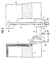
- FIG. 2 shows an additional bypass duct 16 which connects the wind chamber 3 directly to the control valve 15, which regulates the air supply which flows through the openings in the base 7 into the pneumatic conveyor 5.
- the pressure in the wind chamber 3, which is proportional to the height of the fluidized bed, can control the control valve 15 in such a way that it only switches on or off, or implement proportional control in a somewhat more complex form.
- the control valve 15 can be activated solely by mechanical means, in that the pressure in the bypass channel 16 acts directly on membranes or flaps which influence the opening of the control valve 15.
- the setting of the control valve 15 should be such that when the wind chamber pressure exceeds a target value, ie an upper limit value, the air supply with the control valve 15 is either switched on or increased, so that the cone of debris 6, which exits the sand, is reduced the discharge pipe 4 releases. This reduces the wind chamber pressure to a lower limit value, the air supply with the control valve 15 is either reduced or even switched off, and the pouring cone 6 is rebuilt until the sand outlet of the outlet pipe 4 is closed.
- a target value ie an upper limit value
- a temperature sensor 18 is used in the fluidized bed. Both sensors 17 and 18 are connected to a control unit 21 via lines 19 and 20. In the control unit 21, the measured pressures and temperature are compared with the target value curves, and in accordance with the comparison result, the control valve 15 is controlled via the control line 22 and the air supply through the air supply line 14 and the openings in the bottom 7 into the pneumatic conveyor 5 regulated to influence the cone 6.
- control can be reduced to the evaluation of only one measurement signal, either of the pressure in the wind chamber or the temperature in the fluidized bed, and only one corresponding sensor can be installed in the fluidized bed furnace.
- the size of the pneumatic conveyor 5 is essentially determined by the volume of the old foundry sand to be regenerated. For larger volumes, several outflow pipes 14 with subsequent pneumatic conveyors 5 can be used in a parallel arrangement.
- the spatial extent of the pneumatic conveyor 5 is much smaller than the others Individual elements required for regeneration. Due to the simple and the associated great robustness, there is little susceptibility to faults.
Landscapes
- Engineering & Computer Science (AREA)
- Mechanical Engineering (AREA)
- General Engineering & Computer Science (AREA)
- Molds, Cores, And Manufacturing Methods Thereof (AREA)
- Crucibles And Fluidized-Bed Furnaces (AREA)
- Fluidized-Bed Combustion And Resonant Combustion (AREA)
- Devices And Processes Conducted In The Presence Of Fluids And Solid Particles (AREA)
Claims (14)
- Dispositif pour régler l'évacuation de sable par l'intermédiaire d'un tube d'évacuation disposé sur le côté opposé d'une arrivée de sable dans le four à lit fluidisé, lors de la régénération thermique de vieux sable de fonderie, et dans lequel le fond du four à lit fluidisé comporte des ouvertures par lesquelles des gaz chauds parviennent dans le lit fluidisé,
caractérisé en ce que
la sortie pour le sable sortant du tube d'évacuation (4) est disposée à une certaine distance au-dessus du fond (7), pourvu d'ouvertures, d'un convoyeur pneumatique (5), qui est situé au-dessous du fond (2), pourvu d'ouvertures, du four à lit fluidisé (1) de telle sorte qu'il peut se former un cône de déchargement (6), qui peut bloquer la sortie du sable hors du tube d'évacuation (4), et que le courant d'air envoyé à travers le fond (7) du convoyeur (5) peut être appliqué et supprimé ou est réglable. - Dispositif selon la revendication 1, caractérisé en ce qu'au niveau de l'entrée d'air (34) du convoyeur pneumatique (5) est disposée une soupape (15), qui est ouverte ou fermée en fonction de la pression régnant dans la chambre à vent (3) du four à lit fluidisé (1).
- Dispositif selon la revendication 1 ou 2, caractérisé en ce que la soupape (15) est reliée à la chambre à vent (3) par une canalisation de by-pass (16) et que la pression dans la canalisation de by-pass (16) règle directement le degré d'ouverture de la soupape.
- Dispositif selon la revendication 1 ou 2, caractérisé en ce que la soupape (15) est réglable en fonction de la pression, mesurée au moyen d'un capteur de pression (17), dans la chambre à vent (3) et/ou de la température mesurée avec un capteur de température (18) dans le lit fluidisé.
- Dispositif selon les revendications 1 à 4, caractérisé en ce que la distance et/ou la position entre la sortie du sable hors du tube d'évacuation (4) et le fond (7) du convoyeur pneumatique (5) est variable.
- Dispositif selon l'une des revendications 1 à 5, caractérisé en ce que le convoyeur pneumatique (5) est relié, au moyen d'une goulotte de convoyage (8), à un récipient de soufflage (9) et que le vieux sable de fonderie traité par voie thermique peut être amené par un tube de soufflage (11) à l'aide d'un courant d'air dirigé à partir d'une buse de soufflage (10) à un refroidisseur (13) du lit fluidisé.
- Dispositif selon la revendication 6, caractérisé en ce que la distance entre l'entrée du tube de soufflage et la buse de soufflage (10) est variable.
- Dispositif selon les revendications 6 et 7, caractérisé en ce qu'une cloche de renvoi (12) est disposée au-dessus de la sortie du tube de soufflage.
- Procédé pour régler l'évacuation du sable, selon lequel on fait fonctionner le dispositif selon la revendication 1, et selon lequel moyennant un accroissement de l'envoi d'air dans un convoyeur pneumatique (5) branché en aval du four à lit fluidisé (1), à travers le fond (7) pourvu d'ouvertures de ce convoyeur, un cône de déchargement (6) formé entre l'extrémité du tube d'évacuation (4) et le fond (7) est désagrégé et la sortie du sable hors du tube d'évacuation (4) est libérée.
- Procédé selon la revendication 9, caractérisé en ce que l'amenée d'air est réglée en fonction de la pression mesurée dans la chambre à vent (3) du four à lit fluidisé (1) de telle sorte que, lors du dépassement d'une valeur limite supérieure prédéterminée, le débit volumique de l'air arrivant est établi ou accru jusqu'à ce que soit atteinte une valeur limite inférieure de pression.
- Procédé selon les revendications 9 et 10, caractérisé en ce que l'arrivée d'air est réglée en fonction de la pression mesurée dans la chambre à vent (3) du four à lit fluidisé (1) et de la température dans le four à lit fluidisé (1).
- Procédé selon les revendications 9 à 11, caractérisé en ce que la position du fond (7) est modifiée par rapport à la sortie du tube d'évacuation (4).
- Procédé selon les revendicatoons 9 à 12, caractérisé en ce que le vieux sable de fonderie, traité thermiquement, est envoyé au moyen du convoyeur pneumatique (5) à un récipient de soufflage (9) et y est accéléré, au moyen d'une buse de soufflage (10), et par l'intermédiaire d'un tube de soufflage (11) contre une cloche de renvoi (12).
- Procédé selon la revendication 13, caractérisé en ce que la charge de matière du courant d'entraînement est réglée par modification de la distance entre la buse de soufflage (10) et l'entrée du tube de soufflage (11).
Applications Claiming Priority (2)
| Application Number | Priority Date | Filing Date | Title |
|---|---|---|---|
| DE4215867A DE4215867A1 (de) | 1992-05-14 | 1992-05-14 | Verfahren und Vorrichtung zur Regelung des Sandaustrages bei der thermischen Regenerierung von Gießerei-Altsand in Wirbelschichtöfen |
| DE4215867 | 1992-05-14 |
Publications (2)
| Publication Number | Publication Date |
|---|---|
| EP0569945A1 EP0569945A1 (fr) | 1993-11-18 |
| EP0569945B1 true EP0569945B1 (fr) | 1997-04-23 |
Family
ID=6458828
Family Applications (1)
| Application Number | Title | Priority Date | Filing Date |
|---|---|---|---|
| EP93107669A Expired - Lifetime EP0569945B1 (fr) | 1992-05-14 | 1993-05-11 | Procédé et dispositif pour le réglage de la sortie de sable lors de la régénération thermique et vieux sables de fondérie dans des réacteurs à lit fluidisé |
Country Status (7)
| Country | Link |
|---|---|
| US (1) | US5404655A (fr) |
| EP (1) | EP0569945B1 (fr) |
| JP (1) | JPH07115114B2 (fr) |
| KR (1) | KR960010018B1 (fr) |
| AT (1) | ATE152016T1 (fr) |
| DE (2) | DE4215867A1 (fr) |
| ZA (1) | ZA933172B (fr) |
Families Citing this family (4)
| Publication number | Priority date | Publication date | Assignee | Title |
|---|---|---|---|---|
| DE69816612T2 (de) | 1998-08-11 | 2004-06-09 | Fata Aluminium S.P.A. | Einrichtung und Verfahren zum kontinuierlichen Regenerieren von Altsand |
| AT14432U1 (de) * | 2014-06-05 | 2015-11-15 | Binder Co Ag | Verfahren zur Expansion von sandkornförmigem Rohmaterial |
| FI128118B (fi) | 2017-10-25 | 2019-10-15 | Finn Recycling Oy | Hiekan terminen elvytys tai puhdistus |
| CN113136218B (zh) * | 2020-01-17 | 2025-07-11 | 北京航天石化技术装备工程有限公司 | 一种固体热载体炉床层差压的控制系统 |
Family Cites Families (7)
| Publication number | Priority date | Publication date | Assignee | Title |
|---|---|---|---|---|
| CH558674A (de) * | 1971-07-01 | 1975-02-14 | Ciba Geigy Ag | Verfahren und vorrichtung zur herstellung eines granulats. |
| US4144088A (en) * | 1977-01-19 | 1979-03-13 | Kenzler Engineering Company, Inc. | Process of reclaiming used foundry sand |
| DE2708961A1 (de) * | 1977-03-02 | 1978-09-07 | Freier Grunder Eisen Metall | Verfahren und vorrichtung zur herabsetzung des harzanteils von gebrauchtem giessereisand |
| DE3123328C2 (de) * | 1981-06-12 | 1986-03-13 | Johannes Möller Hamburg GmbH & Co KG, 2000 Hamburg | Anordnung zum Austragen von heißer Asche insbesondere aus Wirbelschichtreaktoren und Wirbelschichtöfen |
| DE3636479A1 (de) * | 1986-10-27 | 1988-05-05 | Foerder & Anlagentechnik Gmbh | Verfahren und anordnung zur thermo-mechanischen regenerierung von schuettguetern, insbesondere von giesserei-altsand |
| EP0379684B1 (fr) * | 1988-12-23 | 1993-10-27 | Bühler Ag | Procédé et dispositif pour la cristallisation en continu de polyester |
| US4952246A (en) * | 1989-08-23 | 1990-08-28 | Dependable Foundry Equipment Company, Inc. | Plant and method for reconditioning green foundry sand |
-
1992
- 1992-05-14 DE DE4215867A patent/DE4215867A1/de not_active Withdrawn
-
1993
- 1993-05-06 ZA ZA933172A patent/ZA933172B/xx unknown
- 1993-05-11 EP EP93107669A patent/EP0569945B1/fr not_active Expired - Lifetime
- 1993-05-11 DE DE59306233T patent/DE59306233D1/de not_active Expired - Fee Related
- 1993-05-11 AT AT93107669T patent/ATE152016T1/de not_active IP Right Cessation
- 1993-05-12 US US08/060,255 patent/US5404655A/en not_active Expired - Fee Related
- 1993-05-13 JP JP5111723A patent/JPH07115114B2/ja not_active Expired - Lifetime
- 1993-05-13 KR KR1019930008208A patent/KR960010018B1/ko not_active Expired - Fee Related
Also Published As
| Publication number | Publication date |
|---|---|
| DE4215867A1 (de) | 1993-11-18 |
| US5404655A (en) | 1995-04-11 |
| DE59306233D1 (de) | 1997-05-28 |
| EP0569945A1 (fr) | 1993-11-18 |
| ZA933172B (en) | 1993-12-07 |
| ATE152016T1 (de) | 1997-05-15 |
| JPH0679398A (ja) | 1994-03-22 |
| KR930023689A (ko) | 1993-12-21 |
| KR960010018B1 (ko) | 1996-07-25 |
| JPH07115114B2 (ja) | 1995-12-13 |
Similar Documents
| Publication | Publication Date | Title |
|---|---|---|
| DE69911915T2 (de) | Wirbelschichttrocknungsklassierer | |
| DE2651266A1 (de) | Pulverzufuhrvorrichtung fuer eine stranggussanlage | |
| DE2819184A1 (de) | Fliessbett-verbrennungsvorrichtung mit ascheentfernungseinrichtung | |
| DE3529144A1 (de) | Vorrichtung im wirbelschichtreaktor | |
| AT15001U1 (de) | Verfahren und vorrichtung zur herstellung eines geblähten granulats | |
| DE4218024A1 (de) | Verfahren und vorrichtung zum verhindern einer staubanlagerung in einem verbrennungs- oder schmelzofen | |
| DE1274560B (de) | Vorrichtung zum Entstauben von Industriegasen | |
| EP0569945B1 (fr) | Procédé et dispositif pour le réglage de la sortie de sable lors de la régénération thermique et vieux sables de fondérie dans des réacteurs à lit fluidisé | |
| DE3019047A1 (de) | Anlage zur herstellung von pulver durch zerstaeubung einer schmelze | |
| EP0487829B1 (fr) | Dispositif pour sécher de la matière en vrac | |
| DE2158317C3 (de) | Bandpelletisieranlage | |
| DE2737533A1 (de) | Vorrichtung zum kuehlen von teilchenfoermigem material | |
| DE3123328C2 (de) | Anordnung zum Austragen von heißer Asche insbesondere aus Wirbelschichtreaktoren und Wirbelschichtöfen | |
| DE102018215348A1 (de) | Kühler zum Kühlen von Klinker und Verfahren zum Betreiben eines Kühlers zum Kühlen von Klinker | |
| DE19927447B4 (de) | Zuführvorrichtung zum Zuführen einer vorbehandelten Beschickungsmischung in einen Schmelzofen | |
| DE60220147T2 (de) | Anlage und verfahren zur behandlung von abgasen | |
| DE4244921C2 (de) | Feuerungsanlage für feste Brennstoffe | |
| DD227355A5 (de) | Verfahren und vorrichtung zur herstellung von kugelfoermigen metallischen partikeln | |
| DE2033467C2 (de) | Regeleinrichtung für eine Abfallverbrennungsanordnung | |
| EP0582049A1 (fr) | Procédé et dispositif pour décharger des matériaux solides | |
| DE4322947B4 (de) | Anordnung zur Verbesserung der Verarbeitungsgeigenschaften von Sanden | |
| DE900391C (de) | Verfahren und Vorrichtung zum Raffinieren schmelzfluessiger Metalle, insbesondere Leichtmetalle | |
| DD146847A1 (de) | Kuehltunnel fuer die gesteuerte zwangskuehlung von erhitztem gut,insbesondere von gussstuecken | |
| DE1097414B (de) | Verfahren und Vorrichtung zum kontinuierlichen Behandeln von koernigen oder stueckigen Feststoffen mit Gasen zum Zweck der Trocknung, Kuehlung, Reinigung, Entgasung oder Begasung | |
| EP0726231B1 (fr) | Procédé et appareil pour le traitement thermique de matières solides |
Legal Events
| Date | Code | Title | Description |
|---|---|---|---|
| PUAI | Public reference made under article 153(3) epc to a published international application that has entered the european phase |
Free format text: ORIGINAL CODE: 0009012 |
|
| AK | Designated contracting states |
Kind code of ref document: A1 Designated state(s): AT BE CH DE DK FR GB IT LI LU NL SE |
|
| 17P | Request for examination filed |
Effective date: 19931112 |
|
| 17Q | First examination report despatched |
Effective date: 19951124 |
|
| GRAG | Despatch of communication of intention to grant |
Free format text: ORIGINAL CODE: EPIDOS AGRA |
|
| GRAH | Despatch of communication of intention to grant a patent |
Free format text: ORIGINAL CODE: EPIDOS IGRA |
|
| ITF | It: translation for a ep patent filed | ||
| GRAH | Despatch of communication of intention to grant a patent |
Free format text: ORIGINAL CODE: EPIDOS IGRA |
|
| GRAA | (expected) grant |
Free format text: ORIGINAL CODE: 0009210 |
|
| AK | Designated contracting states |
Kind code of ref document: B1 Designated state(s): AT BE CH DE DK FR GB IT LI LU NL SE |
|
| PG25 | Lapsed in a contracting state [announced via postgrant information from national office to epo] |
Ref country code: NL Effective date: 19970423 Ref country code: DK Effective date: 19970423 |
|
| REF | Corresponds to: |
Ref document number: 152016 Country of ref document: AT Date of ref document: 19970515 Kind code of ref document: T |
|
| REG | Reference to a national code |
Ref country code: CH Ref legal event code: EP |
|
| PG25 | Lapsed in a contracting state [announced via postgrant information from national office to epo] |
Ref country code: LU Free format text: LAPSE BECAUSE OF NON-PAYMENT OF DUE FEES Effective date: 19970511 Ref country code: AT Free format text: LAPSE BECAUSE OF NON-PAYMENT OF DUE FEES Effective date: 19970511 |
|
| GBT | Gb: translation of ep patent filed (gb section 77(6)(a)/1977) |
Effective date: 19970424 |
|
| REF | Corresponds to: |
Ref document number: 59306233 Country of ref document: DE Date of ref document: 19970528 |
|
| PG25 | Lapsed in a contracting state [announced via postgrant information from national office to epo] |
Ref country code: LI Free format text: LAPSE BECAUSE OF NON-PAYMENT OF DUE FEES Effective date: 19970531 Ref country code: CH Free format text: LAPSE BECAUSE OF NON-PAYMENT OF DUE FEES Effective date: 19970531 Ref country code: BE Effective date: 19970531 |
|
| PG25 | Lapsed in a contracting state [announced via postgrant information from national office to epo] |
Ref country code: SE Effective date: 19970723 |
|
| ET | Fr: translation filed | ||
| NLV1 | Nl: lapsed or annulled due to failure to fulfill the requirements of art. 29p and 29m of the patents act | ||
| BERE | Be: lapsed |
Owner name: KGT GIESSEREITECHNIK G.M.B.H. Effective date: 19970531 |
|
| REG | Reference to a national code |
Ref country code: CH Ref legal event code: PL |
|
| PLBE | No opposition filed within time limit |
Free format text: ORIGINAL CODE: 0009261 |
|
| 26N | No opposition filed | ||
| PGFP | Annual fee paid to national office [announced via postgrant information from national office to epo] |
Ref country code: GB Payment date: 19980501 Year of fee payment: 6 |
|
| PGFP | Annual fee paid to national office [announced via postgrant information from national office to epo] |
Ref country code: FR Payment date: 19980529 Year of fee payment: 6 |
|
| PGFP | Annual fee paid to national office [announced via postgrant information from national office to epo] |
Ref country code: DE Payment date: 19980623 Year of fee payment: 6 |
|
| PG25 | Lapsed in a contracting state [announced via postgrant information from national office to epo] |
Ref country code: GB Free format text: LAPSE BECAUSE OF NON-PAYMENT OF DUE FEES Effective date: 19990511 |
|
| GBPC | Gb: european patent ceased through non-payment of renewal fee |
Effective date: 19990511 |
|
| PG25 | Lapsed in a contracting state [announced via postgrant information from national office to epo] |
Ref country code: FR Free format text: LAPSE BECAUSE OF NON-PAYMENT OF DUE FEES Effective date: 20000131 |
|
| PG25 | Lapsed in a contracting state [announced via postgrant information from national office to epo] |
Ref country code: DE Free format text: LAPSE BECAUSE OF NON-PAYMENT OF DUE FEES Effective date: 20000301 |
|
| REG | Reference to a national code |
Ref country code: FR Ref legal event code: ST |
|
| PG25 | Lapsed in a contracting state [announced via postgrant information from national office to epo] |
Ref country code: IT Free format text: LAPSE BECAUSE OF NON-PAYMENT OF DUE FEES Effective date: 20050511 |