EP0569988A2 - Chariot de transport pour objets de type palette - Google Patents
Chariot de transport pour objets de type palette Download PDFInfo
- Publication number
- EP0569988A2 EP0569988A2 EP93107826A EP93107826A EP0569988A2 EP 0569988 A2 EP0569988 A2 EP 0569988A2 EP 93107826 A EP93107826 A EP 93107826A EP 93107826 A EP93107826 A EP 93107826A EP 0569988 A2 EP0569988 A2 EP 0569988A2
- Authority
- EP
- European Patent Office
- Prior art keywords
- chassis
- transport cart
- support
- cart according
- shaped
- Prior art date
- Legal status (The legal status is an assumption and is not a legal conclusion. Google has not performed a legal analysis and makes no representation as to the accuracy of the status listed.)
- Granted
Links
Images




Classifications
-
- B—PERFORMING OPERATIONS; TRANSPORTING
- B62—LAND VEHICLES FOR TRAVELLING OTHERWISE THAN ON RAILS
- B62B—HAND-PROPELLED VEHICLES, e.g. HAND CARTS OR PERAMBULATORS; SLEDGES
- B62B3/00—Hand carts having more than one axis carrying transport wheels; Steering devices therefor; Equipment therefor
- B62B3/04—Hand carts having more than one axis carrying transport wheels; Steering devices therefor; Equipment therefor involving means for grappling or securing in place objects to be carried; Loading or unloading equipment
- B62B3/06—Hand carts having more than one axis carrying transport wheels; Steering devices therefor; Equipment therefor involving means for grappling or securing in place objects to be carried; Loading or unloading equipment for simply clearing the load from the ground
- B62B3/0618—Hand carts having more than one axis carrying transport wheels; Steering devices therefor; Equipment therefor involving means for grappling or securing in place objects to be carried; Loading or unloading equipment for simply clearing the load from the ground using fluid lifting mechanisms
-
- B—PERFORMING OPERATIONS; TRANSPORTING
- B62—LAND VEHICLES FOR TRAVELLING OTHERWISE THAN ON RAILS
- B62B—HAND-PROPELLED VEHICLES, e.g. HAND CARTS OR PERAMBULATORS; SLEDGES
- B62B3/00—Hand carts having more than one axis carrying transport wheels; Steering devices therefor; Equipment therefor
- B62B3/04—Hand carts having more than one axis carrying transport wheels; Steering devices therefor; Equipment therefor involving means for grappling or securing in place objects to be carried; Loading or unloading equipment
-
- B—PERFORMING OPERATIONS; TRANSPORTING
- B62—LAND VEHICLES FOR TRAVELLING OTHERWISE THAN ON RAILS
- B62B—HAND-PROPELLED VEHICLES, e.g. HAND CARTS OR PERAMBULATORS; SLEDGES
- B62B3/00—Hand carts having more than one axis carrying transport wheels; Steering devices therefor; Equipment therefor
- B62B3/04—Hand carts having more than one axis carrying transport wheels; Steering devices therefor; Equipment therefor involving means for grappling or securing in place objects to be carried; Loading or unloading equipment
- B62B3/06—Hand carts having more than one axis carrying transport wheels; Steering devices therefor; Equipment therefor involving means for grappling or securing in place objects to be carried; Loading or unloading equipment for simply clearing the load from the ground
- B62B3/0625—Hand carts having more than one axis carrying transport wheels; Steering devices therefor; Equipment therefor involving means for grappling or securing in place objects to be carried; Loading or unloading equipment for simply clearing the load from the ground using rigid mechanical lifting mechanisms, e.g. levers, cams or gears
-
- B—PERFORMING OPERATIONS; TRANSPORTING
- B66—HOISTING; LIFTING; HAULING
- B66F—HOISTING, LIFTING, HAULING OR PUSHING, NOT OTHERWISE PROVIDED FOR, e.g. DEVICES WHICH APPLY A LIFTING OR PUSHING FORCE DIRECTLY TO THE SURFACE OF A LOAD
- B66F9/00—Devices for lifting or lowering bulky or heavy goods for loading or unloading purposes
- B66F9/06—Devices for lifting or lowering bulky or heavy goods for loading or unloading purposes movable, with their loads, on wheels or the like, e.g. fork-lift trucks
-
- B—PERFORMING OPERATIONS; TRANSPORTING
- B66—HOISTING; LIFTING; HAULING
- B66F—HOISTING, LIFTING, HAULING OR PUSHING, NOT OTHERWISE PROVIDED FOR, e.g. DEVICES WHICH APPLY A LIFTING OR PUSHING FORCE DIRECTLY TO THE SURFACE OF A LOAD
- B66F9/00—Devices for lifting or lowering bulky or heavy goods for loading or unloading purposes
- B66F9/06—Devices for lifting or lowering bulky or heavy goods for loading or unloading purposes movable, with their loads, on wheels or the like, e.g. fork-lift trucks
- B66F9/065—Devices for lifting or lowering bulky or heavy goods for loading or unloading purposes movable, with their loads, on wheels or the like, e.g. fork-lift trucks non-masted
-
- B—PERFORMING OPERATIONS; TRANSPORTING
- B66—HOISTING; LIFTING; HAULING
- B66F—HOISTING, LIFTING, HAULING OR PUSHING, NOT OTHERWISE PROVIDED FOR, e.g. DEVICES WHICH APPLY A LIFTING OR PUSHING FORCE DIRECTLY TO THE SURFACE OF A LOAD
- B66F9/00—Devices for lifting or lowering bulky or heavy goods for loading or unloading purposes
- B66F9/06—Devices for lifting or lowering bulky or heavy goods for loading or unloading purposes movable, with their loads, on wheels or the like, e.g. fork-lift trucks
- B66F9/075—Constructional features or details
- B66F9/07559—Stabilizing means
-
- B—PERFORMING OPERATIONS; TRANSPORTING
- B62—LAND VEHICLES FOR TRAVELLING OTHERWISE THAN ON RAILS
- B62B—HAND-PROPELLED VEHICLES, e.g. HAND CARTS OR PERAMBULATORS; SLEDGES
- B62B2203/00—Grasping, holding, supporting the objects
- B62B2203/20—Grasping, holding, supporting the objects using forks or tines
- B62B2203/24—Changing the position of the fork or supports
-
- B—PERFORMING OPERATIONS; TRANSPORTING
- B62—LAND VEHICLES FOR TRAVELLING OTHERWISE THAN ON RAILS
- B62B—HAND-PROPELLED VEHICLES, e.g. HAND CARTS OR PERAMBULATORS; SLEDGES
- B62B2203/00—Grasping, holding, supporting the objects
- B62B2203/20—Grasping, holding, supporting the objects using forks or tines
- B62B2203/26—Grasping, holding, supporting the objects using forks or tines the fork being independent from the supporting arms in which the wheels are incorporated
Definitions
- the invention relates to a trolley for objects that can be driven under, in particular pallets and the like, consisting of a chassis which is supported against the ground via at least one front and two rear wheels and at least one support part which can be raised relative to the floor, and a device for lifting the support part relative to the chassis and a towering push handle
- a trolley for objects that can be driven under, in particular pallets and the like, consisting of a chassis which is supported against the ground via at least one front and two rear wheels and at least one support part which can be raised relative to the floor, and a device for lifting the support part relative to the chassis and a towering push handle
- piece goods or pallets have to be transported or implemented in a constantly changing order and in particular immediately in succession, for which purpose different types of transport carts must usually be used, since the known types of for transporting pallets are usually carried out with one , if necessary also equipped with a lifting device that can be driven by muscle power, height-adjustable load fork, which is not suitable for transporting smaller piece goods.
- the known types of trolleys suitable for picking up and transporting pallets are distinguished on the one hand by a complex hydraulic design of the lifting device (US Pat. No. 3,612,564) or by the use of the push bar as a drive member for a mechanical lifting device (US Pat 3 290 051).
- a considerable amount of construction is required for the lifting device or its drive, which overall makes the transport cart considerably more expensive, necessary and, in the other case, the use of the push bar as a driving means for the lifting device requires a considerable amount of maneuvering space when using the transport cart.
- the invention has for its object to improve a trolley of the type described above in that that it is suitable for low-cost production and good maneuverability as well as great load-bearing capacity both for the normal transport of general cargo and in particular for moving pallets in a very small space. Furthermore, the trolley should be able to be produced, at least within certain limits, in different sizes, for example as a type series, in the same structural configuration, in particular using largely identical components.
- the invention is also based on the task of further developing a small-sized transport cart so that it is equally good with still low manufacturing costs and optimum maneuverability as well as load-bearing capacity and concealed arrangement of all drive parts for picking up and moving both half and quarter pallets is suitable, even smaller, in particular quarter pallets, can be individually removed from rows standing one behind the other without any particular skill or attention of the personnel and can also be picked up and moved in the transverse direction safely, ie tilt-proof.
- the transport cart should have a sufficient lifting height, at least within certain limits, in order to be able to lift pallets from so-called roll containers or to place them on roll containers.
- the supporting part is designed as a horizontally oriented supporting surface which overlaps the chassis and is articulated in a height-adjustable manner in parallel, horizontal alignment on the chassis by means of a pivoting lever parallelogram pivotable by the drive device.
- the design of the support part as a wing allows the trolley without any additional part and in particular without retrofitting both for the transport of common cargo can also be used to move pallets and also has the advantage of smooth circumferential contours that exclude accidents in particular.
- chassis or load-bearing chassis and the support part forming the wing are each designed as an independently prefabricated or prefabricated unit and can be connected to one another by means of the pairs of swivel levers of the parallel-parallel lever.
- the chassis forms a preassembled unit consisting of two interconnected hollow beams and rollers mounted on them, having a substantially T-shaped outline shape, and furthermore the supporting part as a whole from a pressed sheet metal part then has on its wing an upward, protruding end bend, to which the spars of the push bar are connected, such that the support part together with push bar forms a preassembled unit, in which case the pivot lever of the pivot lever parallelogram representing the connection of the two preassembled units and also all parts of the drive device are arranged fully symmetrically to the longitudinal axis of the longitudinal beam of the T-shaped outline shape of the chassis.
- Such a configuration allows the use of uniformly prefabricated components or component groups for different types of a trolley, in particular it allows the manufacturer a variety of variations, e.g. with regard to the wing size, the design of the push bar and the like ..
- the two interconnected hollow beams forming the chassis are arranged such that the crossbar of the T-shaped outline has a greater distance from the ground than the Longitudinal beams.
- the protruding end bend of the supporting part has a substantially C-shaped cross-sectional shape and, in conjunction with an end plate, forms a box-shaped cover of the drive device, the spars of the pushing bracket on the latter Narrow sides are attached.
- the drive device comprises a two-armed actuating lever designed as a stirrup and a push lever connecting it to the supporting part and a locking device designed as a spring-loaded pedal , wherein the drive device has a total of only two bearing axles, in that the rear pivoting lever pair of the pivoting lever parallelogram and on the bearing axis of the pushing lever pair also the pedal of the locking device are simultaneously mounted on the bearing axis of the kick bracket.
- a design of the drive device that is not only small-sized, but can be used using largely identical parts or parts groups for different designs of the transport cart results from the fact that the two-armed kick bracket of the drive device is mounted on the transverse beam of the chassis so as to be pivotable about an axis parallel to this, and that its two lever arms located with respect to the chassis are each connected to a thrust lever mounted on the upstanding end bend of the supporting part and pivoted at the top end about an axis parallel to the bearing axis of the stirrup.
- a particularly preferred individual embodiment of the locking device is seen in the fact that the pedal forming the locking device for the floor plan of the kick bar is pivoted in the middle by means of a bearing sleeve and is suspended on the bearing axis of the pair of thrust levers and has a locking shoulder on its inner side which, when the locking device is engaged, with the bearing axis of the Pedal bracket cooperates, wherein the pedal forming the locking device is loaded in the direction of engagement by a preferably designed as a leaf spring compression spring and the leaf spring is arranged cantilevered, clamped on one side at the root of the pedal and cooperates with a rod bridging the bottom linkage of the pair of thrust levers. It can then be further provided that the pedal forming the locking device is assigned a device that limits its pivoting mobility, in particular a safety bracket that interacts with a cross member of the drive device.
- the object on which the invention is based in the broader sense is further achieved in that, in conjunction with a suspension of the support part via lever parallelograms on an upstanding support frame of the chassis, the device for lifting the support part by means of a hydraulic pump which can be actuated by means of a pedal and a piston cylinder existing unit is formed and as such is supported at the bottom of the chassis and engages the upper horizontal transverse wall of the upwardly projecting end bend of the support member and that the chassis has a design forming a free space for actuating the pedal of the hydraulic pump.
- the chassis has an essentially T-shaped plan shape
- the crossbar of the T-shape being designed as a positive or negative portal
- the crossbar of the T-shaped plan shape being formed by a bent or built molded part
- the crossbar consists of interconnected hollow support sections which are arranged at a height offset from one another to form a portal, such that the central region of the crossbar is at a greater distance from the floor than its two outer side sections which carry the rear rollers.
- the longitudinal bar of the T-shaped outline shape of the chassis is provided with a sheet metal frame with a vertically directed frontal and vertical shape that is approximately the same as the width of the supporting part Formed sidewalls and at its end associated with the crossbeam has an upward angled portion forming the trestle, such that it is approximately L-shaped in side view, the upward angled angled portion of the longitudinal beam of the chassis forming the trestle at least has approximately the height of the end bend of the supporting part corresponding height.
- the longitudinal bar of the T-shaped chassis can be expedient for the longitudinal bar of the T-shaped chassis to have a profile of its circumferential contour that corresponds to the outline of the supporting part.
- the sheet metal frame which forms the longitudinal beam and is U-shaped in plan view in the region of the axis of the front rollers of the chassis is stiffened by means of at least one cross member and the axis carrying the front rollers over connected to this Tabs is additionally supported.
- the lifting device which is accommodated essentially within the support frame of the chassis and consists of a hydraulic cylinder and a hydraulic pump, is covered to the outside by the fact that the support frame formed by the upward bending of the longitudinal beam of the chassis is closed by means of a cover to form an at least rearwardly closed lifting device receiving box is supplemented.
- the supporting part as a whole is formed by a one-piece sheet-metal pressed part with an essentially C-shaped profile cross-section and then has an upwardly directed, angularly extending end bend at its horizontally oriented supporting surface.
- This design of the supporting part as the supporting surface which extends across all the edges of the wing, allows the transport cart to be used without any additional part and, in particular, without retrofitting, both for the transport of customary piece goods and for moving pallets, and also has the advantage of smooth contours and thus avoiding accident hazards with yourself.
- a preferred design provides that the hydraulic cylinder together with the hydraulic pump is supported on the chassis by means of a cross member attached to the side walls of the chassis, expediently it is further provided that the cross-member supporting the unit consisting of hydraulic cylinder and hydraulic pump on the side walls of the chassis is constructed in a unitary manner with the unit.
- a return spring which is supported in particular on the crossbeam of the chassis and engages the upper transverse wall of the end bend of the support part, is preferably formed by a coil spring.
- the push bar can be removed from the cart at least for shipping, for which purpose it is expediently provided that two sleeve-shaped receptacles for the spar ends, one in particular by a U- Shaped curved bracket section are connected to the push bracket.
- the support part comprises a wing divided into two mutually parallel wing areas by means of a central free space and a hood-like overlapping end bend, which projects vertically with respect to the wing, the supporting part including at least one additional support arm, which can be adjusted from a standby position into an operating position aligned at the same level as its wing areas, whereby the formation of a longitudinal, centrally arranged free space in the wing of the support part or the subdivision of the wing into two wing areas aligned parallel to one another initially allows so-called Pick up half pallets by pushing the trolley under the pallet in such a way that the central support beam of the wing areas is embraced.
- the additional support arms adjusted in their operating position then ensure a sufficient support width for the half-pallet in order to support it against the support part of the transport cart so that it is absolutely secure against tipping.
- the arrangement of at least one additional support arm that can be adjusted into an operating position also enables the tilt-proof reception of so-called quarter pallets in the transverse direction, the trolley with its support part being inserted asymmetrically under the quarter pallet and thus to the latter under the quarter pallet, and one being in its Operating position adjusted additional support arm of the support part brings about a tilt-proof support of the quarter pallet which is asymmetrically resting on the support part.
- the longitudinal and centered clearance to the wing can be dimensioned in terms of its width so that by means of a wing designed in this way on the carrying part of the trolley, piece goods can also be picked up and transported, just as with a trolley with a uniformly continuous carrying surface of the carrying part.
- the trolley is equipped with two additional support arms of the support part and these are pivotably articulated about an axis oriented transversely to the longitudinal extent of the wing areas on the vertically projecting end angle of the support part, the additional support arms of the support part at least have a lateral distance to the wing areas in their operating position.
- this makes it possible to fold the additional support arms out of a folded-up ready position, which in no way influences the conventional use of the transport cart, for example for the transport of piece goods, into an operating position and, on the other hand, ensures are the operating position folded or folded additional support arm (s) absolutely tilt-proof support of half or quarter pallets.
- a further particularly preferred embodiment also provides that the additional support arms of the support part are aligned in their operating position at an angle to the wing areas of the support part, for which purpose the additional support arms are pivoted on the pivot means at each angle by means of articulation axes employed at the longitudinal extent of the support area areas of the support part Support part, in particular its hood-like end bend can be articulated, which can be achieved in an expedient individual configuration in that the additional support arms are each articulated by means of trapezoidal pedestals on the side walls of the hood-like end bend in the plan view, such that the additional support arms in their operating position of the end bend of the supporting part is diverging.
- the additional support arms of the support part each consist of an upright, flat material blank and are each positively supported in their operating position against a stop arranged on the associated pedestal, which is trapezoidal in plan view.
- the additional support arms each have a shorter length than the wing area regions of the support part and that at least one of the two additional support arms has a projection or stop forming an insertion limitation having.
- the stop or projection forming the insertion limit is arranged on the inner surface of the additional support arm (s) facing the support part.
- the hood-like end bend of the support part is designed as a closed box and that the two wing areas are each formed by a U-shaped cross-sectional shape of sheet metal parts.
- the invention also provides that the chassis, which has an essentially T-shaped plan shape, and a support bracket arranged so as to stand out from it, are formed overall from profile material sections or profiled sheet metal material sections, the crossbar of the T-shaped plan shape being formed by a bent or built shaped part is and wherein the longitudinal bar of the T-shaped plan shape is formed by two mutually parallel, mutually spaced profile beams.
- a division into prefabricated assemblies can be provided, such that a push bar can be removed from the cart at least for shipping, for which purpose it is expediently provided that two sleeve-shaped receptacles for the spar ends, in particular by one, are provided on the support frame of the chassis U-shaped hollow profile section formed push bracket are connected.
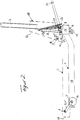
- the drive device for height adjustment of the support part 2 is arranged fully symmetrically with respect to the longitudinal beam 12 of the outline of the chassis and comprises a step bracket 20 and a pair of push levers 21, 21 'articulated thereon the step arm 20 designed as a double-armed lever is pivotally mounted on the crossbeam 13 of the chassis 1 via a bearing bracket 22 and the two levers 21, 21 'of the pair of shoes are articulated on the inside lever arms 23 of the step bracket.
- the pair of thrust levers 21, 21 ' is pivotally articulated about an axis 24 parallel to the bearing axis 8 of the step bracket 20 on the projecting end bend 17 of the supporting part 2, the two levers 21, 21' of the pair of thrust levers being connected to one another by means of a tubular material section 25 forming a bearing sleeve rigid unit are connected.
- the locking device assigned to the drive device comprises a pedal 26 which is arranged in the center of the floor plan of the step bracket 20 and which is rigidly attached to the top of the tubular material section 25 forming the bearing sleeve for the pair of thrust levers 21, 21 'and has a shoulder 27 on its rear side which, when the locking mechanism is engaged a sleeve 28 encompassing the bearing axis 8 of the step bracket rests.
- the pedal 26 is assigned a compression spring designed as a leaf spring 28, which is attached to the top of the pedal 26 and bears against the bottom of the sleeve 31, in such a way that the pedal 26 is acted upon by a spring load acting in the engaging sense of the locking device.
- a catching device which limits the pivoting mobility of the pedal 26 and is designed as a hook bracket 29 and which cooperates with a lever on the support bracket 20 which forms the articulation axis of the push lever pair 21, 21 '.
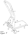
- the trolley consists of three interconnected main assemblies, the first of which is the chassis or chassis 1, the second of which is the supporting part 2 and the third of which is the unit 3 forming the lifting device.
- these main assemblies are supplemented by a push bracket 4 and a return spring 5.
- the chassis 1 forming the first assembly has an essentially T-shaped outline shape, the crossbar 6 of the T-shape being designed as a positive portal in the exemplary embodiment shown, in such a way that the crossbar 6 consists of interconnected hollow support sections 7, 8, 9, which are arranged offset in height from one another to form a portal, in such a way that the central region 8 of the crossbeam 6 is at a greater distance from the floor than its side sections 7 and 9, which lie on the outside and carry the rear rollers 110.
- the longitudinal beam 111 of the T- Shaped plan shape of the chassis 1 is formed by a approximately the width of the support member 2 having a width, in the plan view U-shaped sheet metal frame with vertically directed end 112 and side walls 113 and has at its end associated with the crossbar 6 one forming a bracket 114 , upward bend 115 on such that it in the Side view is approximately L-shaped, the upward-facing, the support bracket 114 forming the longitudinal beam 111 of the chassis 1 has an at least approximately the height of the end angle 116 of the support member 2 corresponding height.
- the longitudinal beam 111 of the chassis 112 has a course of its circumferential contour that corresponds to the plan area of the supporting part 2.
- the sheet metal frame which forms the longitudinal beam 111 and is U-shaped in plan view is stiffened in the region of the axis 117 of the front rollers 118 by means of a crossmember 119, on which the axis 117 carrying the rollers is additionally supported by brackets 120.
- the crossbar 6 of the T-shaped outline shape of the chassis 1 is arranged in corresponding recesses 121 of the upward bend 115 of the longitudinal beam 111.
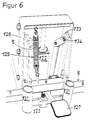
- the lifting device which is accommodated essentially within the support frame 115 of the chassis 1 and consists of a hydraulic cylinder 122 and a hydraulic pump 123, is through a support frame 115 overlapping cover 124, whereby the trestle 115 is complemented at the same time to an at least closed to the rear, receiving the lifting device box.
- the support part 2 as a whole is formed by a one-piece sheet-metal pressed part with an essentially C-shaped profile cross section and is provided with an end bend 126, which is formed above its horizontally oriented support surface 125 and extends over the support frame 115 of the chassis 1, whereby the support part 2 also supports the chassis 1 in the area of its longitudinal beam 111 covers like a hood.
- the support part 2 can be connected to the support frame 115 of the chassis 1 by means of two pairs of parallelogram levers 133, the parallelogram levers 133 being detachably connected at least at one end by means of screw bolts 134 to either the support part 2 or the support frame 115.
- the assembly of the lifting device consisting of the hydraulic cylinder 122 and the hydraulic pump 123 as well as an actuating pedal 127 is supported on the chassis 1 by means of a cross member 128 which can be fastened to the vertically directed side walls of the chassis 1, the cross member 128 being constructed or interlocked with the unit .
- a return spring in particular supported on the crossbar 116 of the chassis 1 and engaging the upper transverse wall of the end bend of the support part 2, is formed in the exemplary embodiment shown by a coil spring 129.
- a push bracket 130 formed by a U-shaped hollow profile section
- two sleeve-shaped receptacles 131 are connected to the support bracket 115 of the chassis 1 for the spar ends of the push bracket.
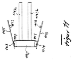
- the trolley consists of three interconnected main assemblies, the first one the chassis or chassis 1, the second the support part 2 and the third, not shown in the drawing, the lifting device is a structural unit. These main assemblies are supplemented by a push bracket 1014 and an actuating pedal 1115 for the lifting device.
- the chassis 1 forming the first assembly has an essentially T-shaped outline shape, the crossbar 1116 of the T-shape being designed as a positive portal, which is supported against the ground by two rollers 1117 arranged on the outside.
- the longitudinal beam 1118 of the T-shaped outline shape of the chassis 1 is formed by two longitudinal beams 1110 arranged at a distance from one another and equipped with rollers 1119 at the front and has a support bracket 1111 at its end associated with the cross beam 1116, the support bracket 1111 pointing upwards forming the bend of the longitudinal beam 1118 of the chassis 1 has a height corresponding at least approximately to the height of an end bend 1112 of the support part 2.
- the support part 2 is formed overall by a one-part or multi-part sheet metal pressed part and is provided with an end bend 1112, which is formed above its horizontally oriented support surface 1113 and extends over the support frame 1111 of the chassis 1, the support part 2 corresponding to the design of the longitudinal beam 1118 of the Chassis 1 is divided into two wing areas 1113a and 1113b by means of a longitudinal central space and the two longitudinal beams 1118 of the chassis 1 overlap with each of the two wing areas 1113a and 1113b, which are approximately U-shaped in cross section.
- the end bend 1112 of the support part 2 which crosses over the support frame 1111 of the chassis 1 is designed as a closed hood and is easily detachably connected to the lifting device, not shown in detail in the exemplary embodiment, by means of a screw connection 1114.
- additional support arms 1115 and 1116 are arranged obliquely to the longitudinal direction of the wing areas by means of the top view of trapezoidal pedestals 1117 1113a and 1113b aligned pivot bearing axles 1118 are pivotally articulated to the end bend 1112 of the support part 2, which crosses the support frame of the chassis 1 in such a way that, in their lowered operating position aligned with the wing area regions 1113a and 1113b, they start from the end bend 1112 of the support part 2 Take the free end of the wing areas 1113a and 1113b diverging position.
- the additional support arms 1115 and 1116 are formed in the exemplary embodiment shown by flat material blanks placed in an upright position and bring about an additional tilt-proof support of the actual load area regions 1113a and 1113b supported load or half or quarter pallet.
- the additional support arms 1115 and 1116 have a shorter length than the two wing areas 1113a and 1113b of the support part 2 and are provided with lateral projections or stops 1120 to obtain an insertion limitation for the support part 2 of the transport cart.
- the two wing areas 1113a and 1113b encompass a central support beam of the half pallet with a small side spacing and form the additional support arms 1115 and 1116, which come into contact at a larger side spacing on the underside of the surface of the pallet, each against the tilt-proof support of the half pallet the support part 2 of the trolley.
- one of the additional support arms 1115 or 1116 When picking up quarter pallets in the transverse direction, which due to the arrangement or design of the foot parts of the quarter pallet only allows the support part 2 of the transport cart to be pushed in unsymmetrically or eccentrically to their entire surface, one of the additional support arms 1115 or 1116, which can be lowered into an operating position, takes over tilt-proof support of the quarter pallet compared to the supporting part 2, so that in the case of the inclusion of quarter pallets only one of the two additional support arms needs to be lowered into the operating position in order to ensure the tilt-proof support of a quarter pallet. For this reason, the two additional support arms 1115 and 1116 can be lowered independently of one another into the operating position. In their standby or carrying position, the two additional support arms 1115 and 1116 are in an upright position, oriented essentially parallel to the end bend 1112 of the support part 2.
Landscapes
- Engineering & Computer Science (AREA)
- Transportation (AREA)
- Mechanical Engineering (AREA)
- Structural Engineering (AREA)
- Chemical & Material Sciences (AREA)
- Combustion & Propulsion (AREA)
- Civil Engineering (AREA)
- Life Sciences & Earth Sciences (AREA)
- Geology (AREA)
- Handcart (AREA)
- Carriers, Traveling Bodies, And Overhead Traveling Cranes (AREA)
Applications Claiming Priority (6)
| Application Number | Priority Date | Filing Date | Title |
|---|---|---|---|
| DE9206563U | 1992-05-14 | ||
| DE9206563U DE9206563U1 (de) | 1992-02-19 | 1992-05-14 | Transportkarre für unterfahrbare Gegenstände |
| DE4217944 | 1992-05-30 | ||
| DE19924217944 DE4217944A1 (de) | 1992-02-19 | 1992-05-30 | Transportkarre für unterfahrbare Gegenstände |
| DE9211190U | 1992-08-20 | ||
| DE9211190U DE9211190U1 (de) | 1992-08-20 | 1992-08-20 | Transportkarre für unterfahrbare Gegenstände |
Publications (3)
| Publication Number | Publication Date |
|---|---|
| EP0569988A2 true EP0569988A2 (fr) | 1993-11-18 |
| EP0569988A3 EP0569988A3 (fr) | 1994-08-03 |
| EP0569988B1 EP0569988B1 (fr) | 1998-08-19 |
Family
ID=27203801
Family Applications (1)
| Application Number | Title | Priority Date | Filing Date |
|---|---|---|---|
| EP93107826A Expired - Lifetime EP0569988B1 (fr) | 1992-05-14 | 1993-05-13 | Chariot de transport pour objets de type palette |
Country Status (4)
| Country | Link |
|---|---|
| EP (1) | EP0569988B1 (fr) |
| AT (1) | ATE169875T1 (fr) |
| DE (1) | DE59308881D1 (fr) |
| DK (1) | DK0569988T3 (fr) |
Cited By (10)
| Publication number | Priority date | Publication date | Assignee | Title |
|---|---|---|---|---|
| EP0726224A3 (fr) * | 1995-02-13 | 1997-03-05 | Liftomatic Material Handling | Dispositif de levage et de transport pour fûts |
| US7712558B2 (en) * | 2007-09-06 | 2010-05-11 | Mh Logistics Corp. | Rolltainer transporter |
| CN104354739A (zh) * | 2014-10-30 | 2015-02-18 | 宁夏共享装备有限公司 | 一种机械式升降转运小车 |
| CN104369753A (zh) * | 2013-08-14 | 2015-02-25 | 中影电影数字制作基地有限公司北京器材租赁分公司 | 一种太空灯推车 |
| CN107487347A (zh) * | 2017-09-15 | 2017-12-19 | 国家电网公司 | 基于同位素示踪技术测抽水蓄能电站地下厂房渗水采集车 |
| CN109398460A (zh) * | 2018-12-27 | 2019-03-01 | 连云港龙塔研磨材料有限公司 | 杠杆式手推车 |
| CN114165053A (zh) * | 2020-09-10 | 2022-03-11 | 广东博智林机器人有限公司 | 流质体运料机器人 |
| US11414115B2 (en) * | 2020-10-16 | 2022-08-16 | Oko Co., Ltd. | Multi-stage load adjustment type moving cart |
| CN116177241A (zh) * | 2022-12-19 | 2023-05-30 | 浙江百世技术有限公司 | 一种仓储物流托盘垛整理装置 |
| IT202200023133A1 (it) * | 2022-11-09 | 2024-05-09 | Nutech S R L | Carrello sollevatore ad azionamento idraulico manuale multi uso |
Family Cites Families (9)
| Publication number | Priority date | Publication date | Assignee | Title |
|---|---|---|---|---|
| US2087861A (en) * | 1934-10-04 | 1937-07-20 | Yale & Towne Mfg Co | Lift truck |
| US2437953A (en) * | 1945-01-17 | 1948-03-16 | Shepard Co Lewis | Elevating truck |
| US2560146A (en) * | 1946-04-27 | 1951-07-10 | Market Forge Company | Lift truck |
| US2669421A (en) * | 1951-10-12 | 1954-02-16 | Ajax Trucks Ltd | Lifting and transporting truck |
| GB956065A (en) * | 1962-02-05 | 1964-04-22 | Takefusa Kikuchi | Improvements relating to load-lifting and transporting trucks |
| DE2427022A1 (de) * | 1974-06-05 | 1975-12-18 | Otto Butter | Lasthebeeinrichtung |
| FR2439742A1 (fr) * | 1978-10-27 | 1980-05-23 | Constr Telephoniques | Chariot elevateur a bras |
| DE3147278A1 (de) * | 1981-11-28 | 1983-06-09 | Küppersbusch AG, 4650 Gelsenkirchen | Fahrbare transport- und beschickungseinrichtung fuer grosskochgeraete |
| GB8814112D0 (en) * | 1988-06-14 | 1988-07-20 | Mallaghan Eng Ltd | Fork lift truck |
-
1993
- 1993-05-13 EP EP93107826A patent/EP0569988B1/fr not_active Expired - Lifetime
- 1993-05-13 DK DK93107826T patent/DK0569988T3/da active
- 1993-05-13 AT AT93107826T patent/ATE169875T1/de active
- 1993-05-13 DE DE59308881T patent/DE59308881D1/de not_active Expired - Fee Related
Cited By (12)
| Publication number | Priority date | Publication date | Assignee | Title |
|---|---|---|---|---|
| EP0726224A3 (fr) * | 1995-02-13 | 1997-03-05 | Liftomatic Material Handling | Dispositif de levage et de transport pour fûts |
| US7712558B2 (en) * | 2007-09-06 | 2010-05-11 | Mh Logistics Corp. | Rolltainer transporter |
| CN104369753A (zh) * | 2013-08-14 | 2015-02-25 | 中影电影数字制作基地有限公司北京器材租赁分公司 | 一种太空灯推车 |
| CN104354739A (zh) * | 2014-10-30 | 2015-02-18 | 宁夏共享装备有限公司 | 一种机械式升降转运小车 |
| CN104354739B (zh) * | 2014-10-30 | 2017-01-25 | 宁夏共享装备有限公司 | 一种机械式升降转运小车 |
| CN107487347A (zh) * | 2017-09-15 | 2017-12-19 | 国家电网公司 | 基于同位素示踪技术测抽水蓄能电站地下厂房渗水采集车 |
| CN109398460A (zh) * | 2018-12-27 | 2019-03-01 | 连云港龙塔研磨材料有限公司 | 杠杆式手推车 |
| CN114165053A (zh) * | 2020-09-10 | 2022-03-11 | 广东博智林机器人有限公司 | 流质体运料机器人 |
| CN114165053B (zh) * | 2020-09-10 | 2023-05-09 | 广东博智林机器人有限公司 | 流质体运料机器人 |
| US11414115B2 (en) * | 2020-10-16 | 2022-08-16 | Oko Co., Ltd. | Multi-stage load adjustment type moving cart |
| IT202200023133A1 (it) * | 2022-11-09 | 2024-05-09 | Nutech S R L | Carrello sollevatore ad azionamento idraulico manuale multi uso |
| CN116177241A (zh) * | 2022-12-19 | 2023-05-30 | 浙江百世技术有限公司 | 一种仓储物流托盘垛整理装置 |
Also Published As
| Publication number | Publication date |
|---|---|
| EP0569988B1 (fr) | 1998-08-19 |
| DK0569988T3 (da) | 1998-10-26 |
| EP0569988A3 (fr) | 1994-08-03 |
| ATE169875T1 (de) | 1998-09-15 |
| DE59308881D1 (de) | 1998-09-24 |
Similar Documents
| Publication | Publication Date | Title |
|---|---|---|
| DE112008003162B4 (de) | Transportsystem, insbesondere mit beweglichen Paletten | |
| DE2926596A1 (de) | Transportkarre | |
| DE8523747U1 (de) | Transportwagen, insbesondere für die Kundschaft in Selbstbedienungsläden | |
| DE3438079A1 (de) | Hubvorrichtung fuer den kofferraum eines fahrzeuges zum entnehmen und einbringen unhandlicher gegenstaende | |
| DE3403585A1 (de) | Arbeitsweise zum verladen eines flurfoerderzeuges sowie stuetzwagen dafuer | |
| EP0569988A2 (fr) | Chariot de transport pour objets de type palette | |
| DE69115893T2 (de) | Transportbehälter | |
| EP0666209A1 (fr) | Chariot de transport, en particulier conteneur roulant comportant des pieds de support retractables | |
| DE29714613U1 (de) | Mobiler Lastenträger | |
| DE3442124A1 (de) | Von hand bewegbarer transportwagen | |
| DE19856584A1 (de) | Einkaufswagen | |
| DE4217944A1 (de) | Transportkarre für unterfahrbare Gegenstände | |
| EP0905004B1 (fr) | Chariot d'achat emboítable | |
| EP0927676B1 (fr) | Chariot de transport emboítable | |
| DE8433784U1 (de) | Von Hand bewegbarer Transportwagen | |
| DE60215797T2 (de) | Beförderungsmittel zur beförderung eines produkts über eine treppe | |
| DE8903451U1 (de) | Mit entsprechenden Wagen schachtelbarer Schubgepäckwagen | |
| DE3909078A1 (de) | Mit entsprechenden wagen schachtelbarer schubgepaeckwagen | |
| DE4227607A1 (de) | Transportkarre für unterfahrbare Gegenstände | |
| DE2364909A1 (de) | Transportwagen fuer stueckgueter | |
| DE2739291A1 (de) | Transportkarren oder -wagen | |
| DE9014238U1 (de) | Verfahrbares Gerät zum getrennten manuellen Sammeln unterschiedlicher Abfallstoffe, insbesondere recyclingfähiger Abfallstoffe | |
| DE29717107U1 (de) | Einkaufswagen und zusätzlicher Lastträger für einen solchen | |
| DE3841004A1 (de) | Mit entsprechenden wagen schachtelbarer schubgepaeckwagen | |
| EP0734933B1 (fr) | Chariot d'achats emboítables |
Legal Events
| Date | Code | Title | Description |
|---|---|---|---|
| PUAI | Public reference made under article 153(3) epc to a published international application that has entered the european phase |
Free format text: ORIGINAL CODE: 0009012 |
|
| 17P | Request for examination filed |
Effective date: 19930513 |
|
| AK | Designated contracting states |
Kind code of ref document: A2 Designated state(s): AT BE CH DE DK ES FR GB GR IT LI NL SE |
|
| PUAL | Search report despatched |
Free format text: ORIGINAL CODE: 0009013 |
|
| AK | Designated contracting states |
Kind code of ref document: A3 Designated state(s): AT BE CH DE DK ES FR GB GR IT LI NL SE |
|
| 17Q | First examination report despatched |
Effective date: 19950720 |
|
| GRAG | Despatch of communication of intention to grant |
Free format text: ORIGINAL CODE: EPIDOS AGRA |
|
| GRAG | Despatch of communication of intention to grant |
Free format text: ORIGINAL CODE: EPIDOS AGRA |
|
| GRAH | Despatch of communication of intention to grant a patent |
Free format text: ORIGINAL CODE: EPIDOS IGRA |
|
| GRAH | Despatch of communication of intention to grant a patent |
Free format text: ORIGINAL CODE: EPIDOS IGRA |
|
| GRAA | (expected) grant |
Free format text: ORIGINAL CODE: 0009210 |
|
| AK | Designated contracting states |
Kind code of ref document: B1 Designated state(s): AT BE CH DE DK ES FR GB GR IT LI NL SE |
|
| PG25 | Lapsed in a contracting state [announced via postgrant information from national office to epo] |
Ref country code: IT Free format text: LAPSE BECAUSE OF FAILURE TO SUBMIT A TRANSLATION OF THE DESCRIPTION OR TO PAY THE FEE WITHIN THE PRE;WARNING: LAPSES OF ITALIAN PATENTS WITH EFFECTIVE DATE BEFORE 2007 MAY HAVE OCCURRED AT ANY TIME BEFORE 2007. THE CORRECT EFFECTIVE DATE MAY BE DIFFERENT FROM THE ONE RECORDED.SCRIBED TIME-LIMIT Effective date: 19980819 Ref country code: GR Free format text: LAPSE BECAUSE OF NON-PAYMENT OF DUE FEES Effective date: 19980819 Ref country code: FR Free format text: LAPSE BECAUSE OF FAILURE TO SUBMIT A TRANSLATION OF THE DESCRIPTION OR TO PAY THE FEE WITHIN THE PRESCRIBED TIME-LIMIT Effective date: 19980819 Ref country code: ES Free format text: THE PATENT HAS BEEN ANNULLED BY A DECISION OF A NATIONAL AUTHORITY Effective date: 19980819 |
|
| REF | Corresponds to: |
Ref document number: 169875 Country of ref document: AT Date of ref document: 19980915 Kind code of ref document: T |
|
| REG | Reference to a national code |
Ref country code: CH Ref legal event code: NV Representative=s name: A. BRAUN, BRAUN, HERITIER, ESCHMANN AG PATENTANWAE Ref country code: CH Ref legal event code: EP |
|
| GBT | Gb: translation of ep patent filed (gb section 77(6)(a)/1977) |
Effective date: 19980821 |
|
| REF | Corresponds to: |
Ref document number: 59308881 Country of ref document: DE Date of ref document: 19980924 |
|
| REG | Reference to a national code |
Ref country code: DK Ref legal event code: T3 |
|
| EN | Fr: translation not filed | ||
| PG25 | Lapsed in a contracting state [announced via postgrant information from national office to epo] |
Ref country code: GB Free format text: LAPSE BECAUSE OF NON-PAYMENT OF DUE FEES Effective date: 19990513 Ref country code: AT Free format text: LAPSE BECAUSE OF NON-PAYMENT OF DUE FEES Effective date: 19990513 |
|
| PG25 | Lapsed in a contracting state [announced via postgrant information from national office to epo] |
Ref country code: SE Free format text: LAPSE BECAUSE OF NON-PAYMENT OF DUE FEES Effective date: 19990514 |
|
| PG25 | Lapsed in a contracting state [announced via postgrant information from national office to epo] |
Ref country code: LI Free format text: LAPSE BECAUSE OF NON-PAYMENT OF DUE FEES Effective date: 19990531 Ref country code: DK Free format text: LAPSE BECAUSE OF NON-PAYMENT OF DUE FEES Effective date: 19990531 Ref country code: CH Free format text: LAPSE BECAUSE OF NON-PAYMENT OF DUE FEES Effective date: 19990531 Ref country code: BE Free format text: LAPSE BECAUSE OF NON-PAYMENT OF DUE FEES Effective date: 19990531 |
|
| PLBE | No opposition filed within time limit |
Free format text: ORIGINAL CODE: 0009261 |
|
| 26N | No opposition filed | ||
| BERE | Be: lapsed |
Owner name: EXPRESSO-DEUTSCHLAND TRANSPORTGERATE G.M.B.H. Effective date: 19990531 |
|
| PG25 | Lapsed in a contracting state [announced via postgrant information from national office to epo] |
Ref country code: NL Free format text: LAPSE BECAUSE OF NON-PAYMENT OF DUE FEES Effective date: 19991201 |
|
| REG | Reference to a national code |
Ref country code: CH Ref legal event code: PL |
|
| GBPC | Gb: european patent ceased through non-payment of renewal fee |
Effective date: 19990513 |
|
| EUG | Se: european patent has lapsed |
Ref document number: 93107826.5 |
|
| NLV4 | Nl: lapsed or anulled due to non-payment of the annual fee |
Effective date: 19991201 |
|
| PG25 | Lapsed in a contracting state [announced via postgrant information from national office to epo] |
Ref country code: DE Free format text: LAPSE BECAUSE OF NON-PAYMENT OF DUE FEES Effective date: 20000301 |
|
| REG | Reference to a national code |
Ref country code: DK Ref legal event code: EBP |