EP0570441B1 - Beleuchtungssystem - Google Patents
Beleuchtungssystem Download PDFInfo
- Publication number
- EP0570441B1 EP0570441B1 EP92904107A EP92904107A EP0570441B1 EP 0570441 B1 EP0570441 B1 EP 0570441B1 EP 92904107 A EP92904107 A EP 92904107A EP 92904107 A EP92904107 A EP 92904107A EP 0570441 B1 EP0570441 B1 EP 0570441B1
- Authority
- EP
- European Patent Office
- Prior art keywords
- strips
- voltage supply
- supply lines
- lighting system
- elongate
- Prior art date
- Legal status (The legal status is an assumption and is not a legal conclusion. Google has not performed a legal analysis and makes no representation as to the accuracy of the status listed.)
- Expired - Lifetime
Links
- 238000010615 ring circuit Methods 0.000 claims description 26
- 230000008878 coupling Effects 0.000 description 54
- 238000010168 coupling process Methods 0.000 description 54
- 238000005859 coupling reaction Methods 0.000 description 54
- 238000005286 illumination Methods 0.000 description 9
- 239000000463 material Substances 0.000 description 7
- 238000010586 diagram Methods 0.000 description 6
- 238000009408 flooring Methods 0.000 description 6
- 230000000694 effects Effects 0.000 description 5
- 230000002093 peripheral effect Effects 0.000 description 5
- 239000012530 fluid Substances 0.000 description 4
- 238000007789 sealing Methods 0.000 description 4
- 238000005476 soldering Methods 0.000 description 4
- RYGMFSIKBFXOCR-UHFFFAOYSA-N Copper Chemical compound [Cu] RYGMFSIKBFXOCR-UHFFFAOYSA-N 0.000 description 3
- 230000015572 biosynthetic process Effects 0.000 description 3
- 238000010276 construction Methods 0.000 description 3
- 229910052802 copper Inorganic materials 0.000 description 3
- 239000010949 copper Substances 0.000 description 3
- 238000005755 formation reaction Methods 0.000 description 3
- 238000012986 modification Methods 0.000 description 3
- 230000004048 modification Effects 0.000 description 3
- 241000269400 Sirenidae Species 0.000 description 2
- 239000004020 conductor Substances 0.000 description 2
- 230000008602 contraction Effects 0.000 description 2
- 239000012777 electrically insulating material Substances 0.000 description 2
- 239000011521 glass Substances 0.000 description 2
- 238000009434 installation Methods 0.000 description 2
- 239000012212 insulator Substances 0.000 description 2
- 239000004922 lacquer Substances 0.000 description 2
- 238000000034 method Methods 0.000 description 2
- 239000003566 sealing material Substances 0.000 description 2
- 208000003443 Unconsciousness Diseases 0.000 description 1
- 239000004411 aluminium Substances 0.000 description 1
- 229910052782 aluminium Inorganic materials 0.000 description 1
- XAGFODPZIPBFFR-UHFFFAOYSA-N aluminium Chemical compound [Al] XAGFODPZIPBFFR-UHFFFAOYSA-N 0.000 description 1
- 238000004891 communication Methods 0.000 description 1
- 238000005520 cutting process Methods 0.000 description 1
- 239000003000 extruded plastic Substances 0.000 description 1
- 238000001125 extrusion Methods 0.000 description 1
- 230000004907 flux Effects 0.000 description 1
- 239000003292 glue Substances 0.000 description 1
- 230000001788 irregular Effects 0.000 description 1
- 238000004519 manufacturing process Methods 0.000 description 1
- 229910052751 metal Inorganic materials 0.000 description 1
- 239000002184 metal Substances 0.000 description 1
- 238000007254 oxidation reaction Methods 0.000 description 1
- 239000004033 plastic Substances 0.000 description 1
- 229920003023 plastic Polymers 0.000 description 1
- 239000004417 polycarbonate Substances 0.000 description 1
- 229920000515 polycarbonate Polymers 0.000 description 1
- 238000004382 potting Methods 0.000 description 1
- 239000000565 sealant Substances 0.000 description 1
- 229910000679 solder Inorganic materials 0.000 description 1
- 125000006850 spacer group Chemical group 0.000 description 1
- 238000003860 storage Methods 0.000 description 1
- 239000000758 substrate Substances 0.000 description 1
- 239000012780 transparent material Substances 0.000 description 1
- 239000011800 void material Substances 0.000 description 1
Images












Classifications
-
- F—MECHANICAL ENGINEERING; LIGHTING; HEATING; WEAPONS; BLASTING
- F21—LIGHTING
- F21V—FUNCTIONAL FEATURES OR DETAILS OF LIGHTING DEVICES OR SYSTEMS THEREOF; STRUCTURAL COMBINATIONS OF LIGHTING DEVICES WITH OTHER ARTICLES, NOT OTHERWISE PROVIDED FOR
- F21V23/00—Arrangement of electric circuit elements in or on lighting devices
- F21V23/06—Arrangement of electric circuit elements in or on lighting devices the elements being coupling devices, e.g. connectors
-
- F—MECHANICAL ENGINEERING; LIGHTING; HEATING; WEAPONS; BLASTING
- F21—LIGHTING
- F21S—NON-PORTABLE LIGHTING DEVICES; SYSTEMS THEREOF; VEHICLE LIGHTING DEVICES SPECIALLY ADAPTED FOR VEHICLE EXTERIORS
- F21S4/00—Lighting devices or systems using a string or strip of light sources
- F21S4/20—Lighting devices or systems using a string or strip of light sources with light sources held by or within elongate supports
-
- F—MECHANICAL ENGINEERING; LIGHTING; HEATING; WEAPONS; BLASTING
- F21—LIGHTING
- F21V—FUNCTIONAL FEATURES OR DETAILS OF LIGHTING DEVICES OR SYSTEMS THEREOF; STRUCTURAL COMBINATIONS OF LIGHTING DEVICES WITH OTHER ARTICLES, NOT OTHERWISE PROVIDED FOR
- F21V23/00—Arrangement of electric circuit elements in or on lighting devices
-
- F—MECHANICAL ENGINEERING; LIGHTING; HEATING; WEAPONS; BLASTING
- F21—LIGHTING
- F21S—NON-PORTABLE LIGHTING DEVICES; SYSTEMS THEREOF; VEHICLE LIGHTING DEVICES SPECIALLY ADAPTED FOR VEHICLE EXTERIORS
- F21S8/00—Lighting devices intended for fixed installation
- F21S8/03—Lighting devices intended for fixed installation of surface-mounted type
- F21S8/032—Lighting devices intended for fixed installation of surface-mounted type the surface being a floor or like ground surface, e.g. pavement
-
- F—MECHANICAL ENGINEERING; LIGHTING; HEATING; WEAPONS; BLASTING
- F21—LIGHTING
- F21S—NON-PORTABLE LIGHTING DEVICES; SYSTEMS THEREOF; VEHICLE LIGHTING DEVICES SPECIALLY ADAPTED FOR VEHICLE EXTERIORS
- F21S8/00—Lighting devices intended for fixed installation
- F21S8/03—Lighting devices intended for fixed installation of surface-mounted type
- F21S8/033—Lighting devices intended for fixed installation of surface-mounted type the surface being a wall or like vertical structure, e.g. building facade
-
- F—MECHANICAL ENGINEERING; LIGHTING; HEATING; WEAPONS; BLASTING
- F21—LIGHTING
- F21Y—INDEXING SCHEME ASSOCIATED WITH SUBCLASSES F21K, F21L, F21S and F21V, RELATING TO THE FORM OR THE KIND OF THE LIGHT SOURCES OR OF THE COLOUR OF THE LIGHT EMITTED
- F21Y2115/00—Light-generating elements of semiconductor light sources
- F21Y2115/10—Light-emitting diodes [LED]
Definitions
- This invention relates to a lighting system which enables elongate lengths of illumination to be provided for a wide range of decorative, safety and other applications.
- Linear lighting systems used hitherto have generally been in the form of extruded tubing of a resilient, translucent or transparent material, e.g. extruded plastics tubing.
- the tubing is illuminated by a series of bulbs connected together by electric wiring to form an elongate lighting string which is threaded through the tubing to provide an internal illumination means therefor.
- the tubular strip is then located where desired to provide an elongate lighting system for decorative or safety purposes.
- a length of such illuminated tubing may be provided in a non-slip nosing across the front edges of the steps of a staircase.
- the lighting system may be used in flooring systems e.g. at a junction between different types of flooring or floor covering. It may be provided as a decorative embellishment e.g. on walls, or display systems, or along bar pelmets, wherever a decorative pencil-line of light is desired.
- the lighting system may follow nonlinear paths, e.g. wound as a shallow spiral around columns or pillars.
- a length of the wiring incorporating the spaced apart illuminating elements does not provide a standard predictable length thereof owing to the flexibility of the wire connectors of the illuminating device which are soldered to the intermediate lengths of connecting wiring. Over a relatively long stretch there can be a very significant expansion or contraction of a supplied length of the illumination wiring resulting in a discrepancy with the length over which the illumination is required to extend.
- the illumination wiring which is usually stored on a roll, is relatively brittle owing to the soldered wire connectors associated with the illuminating devices, which are free to bend.
- US-4,654,765 teaches an elongate lighting assembly which can be produced from insulated strips having electrical conductors thereon.
- the light bulbs are connected in parallel between the voltage supply lines.
- This specification is concerned with a method of mounting the bulbs on the strips in an easily replaceable fashion.
- This system therefore utilizes an entirely parallel arrangement of the light bulbs on a set of similar length strips so that the full supply voltage is applied to each light bulb, which in some applications prevents the use of relatively low voltage bulbs.
- US-4,607,317 discloses connectors for connecting together elongate lighting circuits to form a linear strip.
- each module is of the same length and requires to be cut at specific marks in order to tailor the lighting assembly to specific requirements. This limits the particular lengths which can be accommodated and makes for a relatively cumbersome procedure on site.
- US-3,755,663 discloses a display device comprising miniature lamps connected in series to form substrings which are coupled in parallel between a pair of parallel supply conductors. This assembly is then slidably inserted in a transparent flexible tube. The tube can be cut as desired but only between the substrings. This again limits the particular lengths which can be accommodated and the overall system is relatively cumbersome to assemble and to adapt to specific requirements on site.
- EP-A-0,336,601 describes a lighting system comprising a set of voltage compatible printed circuit boards of different finite lengths, each having a series connected set of illuminating devices connected in parallel between voltage supply lines provided on the strips.
- One strip may have a single illuminating device and a compensating resistor connected together in series with the series connection being connected in parallel across the voltage supply lines.
- the invention seeks to provide improvements in or modifications of the lighting system illustrated in EP-A-0,336,601 to provide improved performance over relatively long length, and/or to provide additional control or constructional modifications of the lighting system for more flexible practical operations thereof.
- the invention provides a lighting system in accordance with Claim 1.
- the invention also provides a lighting system in accordance with Claim 8.
- the invention further provides a lighting system in accordance with Claim 10.
- Each of said strips may be in the form of a printed circuit board.
- Connector means may be provided, the connector means comprising at least one connector member for location between a pair of adjacent strips and having means for resiliently gripping each of said juxtaposed ends of the strips, and means for making an electrical connection between the adjacent ends of said elongate electrical lighting circuits associated with the strips.
- a lighting system may include a voltage supply connecting means for supplying a voltage to said continuous electrical lighting circuit at one or both ends thereof, said voltage supply connecting means comprising a terminal portion adapted to be resiliently gripped by a connector member as aforesaid which is to be resiliently engaged with one end of one of said strips, and having electrical connecting means for making an electrical connection between the electrical connection means of that connector member and a voltage supply.
- a lighting system may include flexible connecting means for electrically connecting a pair of strips which can be set at different angular positions with respect to one another, said flexible connecting means comprising connector portions each adapted to be resiliently gripped by a respective one of a pair of said connector members which are to be resiliently engaged with adjacent ends of said pair of strips, respectively; flexible means connecting said connector portion; and electrical connecting means for making an electrical connection between the electrical connection means of said pair of connector members.
- a lighting system according to the invention may further include an elongate tubular container having a translucent or transparent wall or wall portion, for receiving said plurality of elongate strips when connected by said connector means.
- Said tubular container may have a removably mounted wall section extending along its length.
- Said tubular container may comprise an elongate base channel-section strip, and an elongate, translucent cover strip which can be removably engaged with the base strip to close the channel-section thereof.
- Interengageable snap fastening means may be provided on said base strip and said cover strip.
- Said base strip may be made of a resilient electrically insulating material.
- the base strip may be metallic and relatively rigid, with an internal lining of an electrically insulating material provided to isolate said lighting circuit from the metallic base strip.
- a plurality of base strips and cooperating cover strips which can be secured together may be provided to form required lengths thereof.
- Gasket means may be provided for effecting waterproof joints between adjacent base and cover strip combinations.
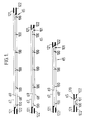
- Figure 1 illustrates the lighting system of Figure 6 of EP-A-0,336,601 comprising a set of a number of different length, flexible, circuit boards on each of which the electric circuitry is arranged to provide a series connection between the lamp elements.
- Each circuit board (65) has two voltage supply lines (67,68) and an electric line (69) connected in parallel across the voltage supply lines (67,68), which connects in series the lamps associated with that board and any compensating resistor.
- the system illustrated in Fig. 1 comprises four different, finite lengths of circuit board, having circuitry for mounting six, five, four and one lamp, respectively, at regularly spaced positions (100).
- an appropriate resistor is generally mounted at a position (101) in order to make all the circuit boards in the set voltage compatible with one another whereby the resistance of the series connected elements is the same for each circuit board of the set.
- lamps or LEDs (60) of the same voltage rating are used throughout, although this is not essential.
- appropriate resistors (66) are used to make all the circuit boards in the set voltage compatible with each other and with the desired supply voltage.
- different sets of standard circuit boards can be provided having different spacings between the location positions of the lamps for any linear length of illumination constructed by coupling the appropriate number and size of circuit boards end to end using coupling elements described below. Examples of such spacings are 50 mm, 75 mm and 100 mm. However in other constructions irregular spacings may be selected for special effects.
- Each coupling element (110) comprises an outer housing (111) comprising an upper part (112) and a lower part (113) snap fitted together.
- Each housing part (112,113) comprises an oblong tray-like member having upstanding peripheral wall portions with resilient pegs (114) provided on abutting edges of the wall portions of the two housing parts (112,113) to engage in corresponding apertures in the opposite abutting edges to provide a snap connection means for the two housing parts, which are disposed in inverted positions with respect to one another.
- the end walls of the housing parts (112,113) are recessed to provide an entry slot (115) for receiving end portions of two circuit boards to be joined end to end by the coupling element (110).
- Three location formations (118) of oblong cross section are integrally formed between the dividing walls (116) and the longitudinal side walls of the parts (112,113) for engagement in centrally located recesses (119) in the connecting elements (117).
- Each connecting element (117) has, at each end, a pair of resilient forks (120) for making electrical connections with the circuitry provided on the circuit boards (65).
- a voltage supply connector element (1120) is provided for coupling to one end of a linear series of circuit boards (65) joined together by coupling elements (110).
- the connector element (1120) includes a terminal portion provided by a short strip of circuit board (1121) having a circuit track arrangement, as illustrated in Fig. 14C, provided thereon.
- the circuit track comprises a negative electric line (1122) and a positive electric line (1123) which has connector points (1124) for connection therein, e.g. by soldering, of a fuse (1125).
- a supply cable (1126) has positive and negative feed wires (1127,1128) which are connected by soldering to positive and negative terminal connector points (1129,1130) on the circuit board (1121).
- the free end portion of the circuit board (1121) is inserted into a slot (115) of a coupling element (110) located at the end of a circuit board (65) disposed at one end of the linear series thereof.
- the outer pair of electrical connecting elements (117) of the coupling element make electrical contact with the positive and negative lines (1123,1122), on the circuit board (1121) to connect the supply voltage across the voltage supply lines (67,68) on the circuit board (65), to provide the voltage supply of the lighting system.
- a flexible connecting device (130) for allowing the connection of adjacent circuit boards in a series thereof, which boards may be set at different angular positions relative to one another.
- the device (130) comprises a pair of similar connector portions (131) made of a short strip of circuit board having a circuit provided thereon, as illustrated in Fig. 5C, consisting of three electric lines, i.e. positive line (132), a negative line (133) and a central line (134).
- the connector portions (131) are joined by flexible jumper wires (136,137,138) which electrically connect the positive lines (132), the negative lines (133) and the central lines (134) on the connector portions (131).
- Circuit board (65) can be cut to fit around each corner with the cut pieces then being coupled together using flexible connector devices (130). Firstly, coupling elements or devices (110) are engaged with the cut ends of the circuit board (65). Then, the connecting portions (131) of a connector device (130) are engaged in the open slots (115) of the respective coupling devices (110).
- the flexible jumper wires allow the cut sections of the circuit boards (65) to be located along different sides of the aforesaid structure.
- the voltage supply lines (67,68) of the two parts of the severed circuit board (65) are connected by the jumper wires (136,137) and the series connection lines (69) are connected by the jumper wire (138).
- circuit boards (65) which fit precisely the lengths along each side of the rectangular structure without any need for cutting any of the circuit boards (65).
- the same coupling devices (110) and flexible connector devices (130) are utilized at the corners, but in this arrangement the central jumper wire (138) is redundant in operation.
- voltage supply connectors may be connected to both ends of the electrically coupled series of circuit boards (65) to maintain the voltage along the entire length of the system.
- a set of calculation charts are preferably provided for each set of circuit boards for operation at a predetermined supply voltage and using illuminating devices of a predetermined operating voltage.
- the charts give a concordance between the number of lamps required, at the preselected spacing therebetween, for any length as measured on site.
- a further concordance chart then gives the required number of circuit boards of the different lengths in the set for that length in dependence on the number of lamps required.
- the "series-parallel" arrangement is advantageous because the lamps required are of lower rated voltages so that a greatly reduced current flow, e.g. one quarter the current of a similar parallel arrangement, is present in operation of the system. This provides a safer system which is generally more compact because lower rated, and therefore smaller components, are needed.
- a specific example of a practical system according to the invention is designed to operate at 24V (AC or DC) with lamps of 5V for a "series-parallel" arrangement, and a maximum current flow of 3 amps.
- a lighting system according to the invention would normally be supplied as a kit comprising standard finite length of flexible circuit boards and coupling elements allowing any required linear length to be built up from these components.
- the positioning of the lamps on the circuit boards, and the length of the coupling elements is such that, when a set of such boards are coupled in a linear series, the required predetermined spacing of the lamps along the entire linear length of the coupled boards is achieved.
- further boards may be provided for an end of any coupled series to accommodate a voltage supply connecting element whilst still maintaining the required predetermined spacing relationship between the lamps along the entire length of any coupled series of circuit boards.
- Each strip (65) may be, for example 50 cm long, 5 mm wide and 1 mm thick. Ten or twenty strips and copper tracking thereof can be formed side by side on a single substrate. A router may separate the individual strips leaving connecting pips therebetween. Alternatively no routing may be carried; instead the strips may be separated at a later stage by a multi-saw device. The lamps and resistors are then inserted on the upper sides of the strips with the terminal portions pushed through the strips to engage solder pads on the copper tracking formed on the underside of the strips. The terminals are cropped and soldered to those pads. The boards are then introduced into a defluxing bath where they are degreased and defluxed. They are blasted with lacquer or other insulating sealant in order to protect the copper tracking from oxidization. After the lacquer has dried the individual circuit boards are snapped apart and finished to remove the connecting pips or are separated by a multi-saw device.
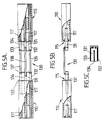
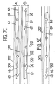
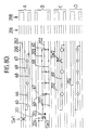
- FIGS 6A - 6F illustrate schematically an embodiment of the invention in the form of a lighting system comprising a set of printed circuit board elements of different finite lengths.
- This system is similar to the system illustrated in Figure 1, the principle difference being that the elongate electrical circuits on the elements have been modified. The following description of this system will therefore be directed to those modifications. Similar parts have been given similar reference numerals.
- each voltage compatible PCB element in the set has, in addition to the pair of voltage supply lines (67,68) and the series-parallel line (69), a pair of ring circuit voltage supply lines (200,201) and a control signal/data line (202).
- coupling elements of the type illustrated in Figs. 3A - 3D may be used, as well as, when required, flexible connecting devices of the type illustrated in Figs. 5A - 5C.
- These coupling elements and connecting devices will be provided with additional electrical connecting elements, e.g. resilient forks (120) and jumper wires (136-138), to provide electrical connections between the respective ring circuit voltage supply lines (200,201) and the control signal/data lines (202) on adjacent strips connected thereby.
- a supply voltage is connected to the voltage supply lines (67,68) and the ring circuit voltage supply lines (200,201), e.g. by a voltage supply connector element of the general type shown in Figs. 4A - 4D, modified to have additional circuit supply lines and electrical connectors to connect also the two ring circuit voltage supply lines (200,201) to the supply voltage.
- the positive and negative ring circuit voltage supply lines (200,201) are connected directly to the positive and negative voltage supply lines (67,68), respectively.
- This can be achieved by using an additional coupling element fitted onto the terminal circuit board of the series and having fitted in its opposite receiving section a small circuit board element having the required electrical bridging circuits provided thereon.
- Such an arrangement is illustrated in the embodiment of Figs. 8A - 8I.
- the control signal/data line (202) provides a further facility to the system whereby control signal or data can be transmitted to control equipment positioned at selected locations along a lighting system assembled from a selected plurality of the circuit boards mechanically and electrically connected in an end-to-end relationship.
- control equipment positioned at selected locations along a lighting system assembled from a selected plurality of the circuit boards mechanically and electrically connected in an end-to-end relationship.
- switches may be incorporated in the electric circuits provided on the circuit boards themselves or ancillary equipment, e.g. external lights, sirens or other electrically or mechanically operated equipment having switch control means, and stationed near to the path of the electric lighting system.
- Such switches can be controlled by receiving specific signals, e.g.
- Switches associated with external ancillary equipment can be electrically connected to the control line (202), e.g. by using a flexible connecting device of the type shown in Figs. 5A - 5C, between adjacent strip at the location of that equipment, and electrically connecting the switches to the jumper wire (136-138) associated with the control line (202) by splicing into that jumper wire an electrical connecting wire which is then connected to the control switch of the ancillary piece of equipment.
- ring circuit voltage supply lines (200,201) or the control line (202) can be omitted for certain applications.
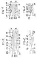
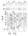
- FIGS 7A - 7F illustrate schematically the electric circuits of a set of printed circuit board constituting a second embodiment.
- This embodiment is similar to the first embodiment of Figs. 6A - 6F and similar parts have been given similar reference numerals.
- the principle difference is that two separate lighting circuits (A,B) are provided on each circuit board.
- Each circuit comprises a set of six electric lines consisting of voltage supply lines (67,68), a series line (69) of illuminating devices, ring voltage supply lines (200,201) and a control line (202).
- the operation of the two circuits (A,B) are generally the same and in accordance with the first embodiment.
- the same or different voltage supplies may be connected to each circuit.
- each circuit (A and B) e.g. from a common set of voltage supply lines (67,68)
- additional resistance by selection of resistors (66) in circuit (B)
- one circuit (A) can be used to provide light of high luminous flux value giving a high light output, e.g. for an emergency situation.
- the other circuit (B) can be used to provide a lower light output, e.g. to provide a pencil-line of light giving a permanent guide along a selected path to designate boundaries of such path or to indicate a path to be followed for various purposes.
- either or both the ring circuit lines (200,201) and the control line (202) of either or both circuits (A and B) can be omitted for particular applications or a single set of lines (200,201) and/or control line (202) common to both circuits (A and B) could be utilized. If both the ring circuit lines (200,201) and the control line (201) are omitted, the embodiment of the invention still provides two separate lighting circuits which can be used for different circumstances or uses as mentioned above.
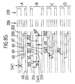
- Figs. 8A - 8I comprises a lighting system comprising a set of different length circuit boards each having four separate light circuits (A - D) provided thereon.
- Circuits (A,C and D) are similar "series-parallel" circuits but possibly running at different voltages with different types of illuminating devices of different rated voltages and located at different spacings, each circuit adapted for different operational purposes.
- a double switch (SW1) is provided in one voltage supply line (67) and the corresponding ring circuit voltage line (200) under the control of a specific signal transmitted along the control line (202).
- the switch (SW1) is normally closed but is opened when the specific control signal for that switch is received, to break both lines (200,202) at that point.
- the switch (SW1) of each such board can be separately addressed by a respective control signal transmitted along control line (202) to break the voltage supply at the position of the respective switch whereby no voltage is supplied to the illuminating devices (200) downstream of that point so that the light is terminated at that point or vice versa.
- a single switch (SW2) is provided in the series-parallel line (69) of each such circuit, under the control of a specific control signal transmitted along the control line (202).
- the illuminating devices of each circuit board can be switched off by transmitting the respective control signal for the switch (SW2) on that board along the control line (202).
- SW2 switch
- many specific effects can be achieved in practice, e.g. switching off specific sections of the elongate lighting, or flashing specific sections by switching such sections on and off sequentially, or producing a flashing sequence which flows along the length of the elongate lighting to indicate direction along the lighting system to a particular point which could for example be an emergency exit.
- control line (202) is provided to control external ancillary equipment, e.g. spotlights, sirens, emergency warning signs, etc., provided at locations along the length of the lighting system.
- the control switches of such equipment are electrically connected to the control (202) to receive control signals transmitted therealong.
- the strip connector (206) include a flexible connector of the type shown in Figs. 5A - 5C, with a connector lead for the switch of the external equipment being spliced into the jumper wire for the control line (202) of circuit (D).
- This lighting system includes a circuit (B) which provides a set of illuminating devices, lamps (60) and LEDs (60'), which can be connected individually in parallel across the voltage supply lines (67,68).
- a spur line (203) is provided on each board from one (67) of the voltage supply lines and pairs of corresponding connection points (207) on the spur line (203) and the second voltage supply line (68) are provided at spaced intervals along the lengths of the boards between which illuminating devices (60,60') can be selectively connected as required.
- a diode (204) is inserted in the spur line (203) which transforms an AC supply across the voltage supply lines (67,68) into a DC supply for the LEDs (60').
- the spur line (203) is controlled, downstream of diode (204) by a two-way switch (SW3) which is addressed by a respective specific control system transmitted along control line (202).
- the switch (SW3) in one position connects the spur line (203) to the voltage supply line (67) through the diode (204) and, in a second position, through a direct line (205).
- This circuit (B) normally operates from an AC supply with the switch (SW3) addressed by a control signal to latch in its first position to connect with respect to the diode (204) which rectifies the AC supply to provide the necessary DC supply for the LEDs (60'). Failure of the AC supply could facilitate an automatic switch-over to an emergency battery supply. This requires removal of the original control signal along line (202) whereby switch (SW3) switches over to its second position so that the battery supply is then connected directly to the spur line (203) through line (205).
- FIGS 8A - 8I also illustrate schematically the electrical circuits of resilient coupling elements (206) for connecting a selected series of the circuit boards in an end-to-end relationship.
- Each coupling element has a series of connections for each of the circuits (A-D).
- circuits (A,C and D) there are electrical connections for each of the voltage supply lines (67,68), the series-parallel line (69), the ring circuit lines (200,201) and the control line (202). Normally the connection for series-parallel line (69) is only used, when severed portions of one particular circuit board is required for a particular installation.
- circuit (B) there are electrical connections for each of the voltage supply lines (67,68), the ring circuit lines (200,201), the control line (202) and the voltage supply spur line (203).
- the electrical connection for the spur line (203) is again only used if an individual circuit board has to be cut during installation.
- Figures 8A - 8I further illustrate schematically a further circuit board (208) for location at a remote end of a series of circuit boards.
- the free end of the last circuit board of the series has a coupling element (206) attached thereto.
- the circuit board (208) is then connected to that circuit board by that coupling element.
- the circuit board (208) merely provides electric connections between the ring circuit lines (200,201) of each circuit (A - D) to its respective voltage supply line (67,68).
- each of the circuits (A - D) may be located side by side across each circuit board.
- some of the electric lines may be provided on opposite sides of the circuit boards with the electrical connections, where necessary, being made through the circuit boards.
- the lines may be provided in three or more planes with some of the lines being sandwiched between layers of the circuit board material.
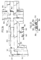
- Figure 9 is a perspective illustration of a circuit board according to Fig. 8 wherein the ring circuit voltage supply lines (200,201) and the control signal line (202) are provided on the underside of the circuit boards (400).
- the light sources (60) of circuit (D) are laid flat on the circuit board (400) and a layer of resilient, heat resisting, cushioning material (401) is provided on the circuit board (400) beneath those light sources (60). This acts to prevent external vibrations from being transmitted through the housing via adjoining circuitry or components thereof and likewise being transmitted along the circuit board resulting in vibration damaging any filament or similar light emitting part of any given light source. End sections of a coupling device (206) is also illustrated.
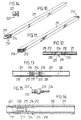
- Figures 10 - 15 illustrate diagrammatically components of another embodiment of the invention.
- a set of printed circuit boards (210), in accordance with Figure 1 or Figure 6 or Figure 7 or Figure 8, are located in rectangular-section tubular, translucent housings (211), to provide a system which is water-sealed at least when the individual modular components are assembled to form an elongate lighting system.
- a planar sealing element (212) is positioned on each end of the printed circuit board (211) with an electrical terminal portion thereof projecting through a slit in the seal (212).
- the outer periphery of the seal resiliently engages the inner periphery of the tubular housing (211) to support the circuit board (210) therein.
- Adjacent housings (211) are connected end-to-end by a coupling device (213) made of a resilient sealing material.
- the device (213) has a central outer peripheral flange (214) which fits and bridges between the end faces of the housings (211).
- the end sections of the device (213) fit within the end portions of the housings (211) and have outer peripheral ribs or O-ring seals (215) which seal within the housings.
- FIG. 14 illustrates an end plug (220) for providing a terminal fitting for a series of modules (211) connected end-to-end.
- the end plug (220) provides an end seal for the assembly, and may include circuitry for electrically connecting the remote ends of the voltage supply lines and ring circuit voltage supply lines provided on the circuit board (210) in the end housing (213) in which the plug is fitted.
- the plug includes a peripheral seal or O-ring (221) for sealing with the housing (211).
- Figure 15 illustrates one end of a flexible coupling device (222) comprising a pair of plug elements (223) connected by jumper leads (224). Each plug element (223) is also provided with a peripheral seal (224).
- a coupling device could have jumper leads of a considerable length, e.g. 10 metres, for applications where a series of spaced apart light strips are desired.
- Figure 16 illustrates a modified embodiment in which the circuit board (210) within tubular housing (211) has terminal connectors in the form of a bunch of wires projecting from the electric terminals at an end of the circuit board (210).
- the circuit board (210) is held by a connector (218) fitted within the housing (211) with a plug (212) being pushed into the connector (218) and supported on a support cup (213).
- An annular cushioning gasket (214) adjoins the support cup (213) and a cable grip (215) is provided to grip the terminal cables of the circuit board which extend through the central void (216) defined within the gasket (214).
- a tube bung (217) is located at the end of the housing (211) and has a serrated inner surface.
- An annular adapter (219) has one narrower end section (220) having an outer serrated section which locks within the bung (217) and a larger end section (221) projecting out of the housing and also having an outer serrated surface.
- the wire terminals extending through the adapter (219) are connected, e.g. by soldering, to those of an adjacent module and a fluid resistant sleeve encases the wires and is pushed onto the serrated outer surfaces of the projecting ends (221) of the adapters (219) of the two modules to provide a fluid resistant connection therebetween.
- coupling elements (230) having embedded therein electric connecting forks (231) are fixedly located in the housing ends by a fixing element (232), e.g. a screw, dowel or potting material, extending through a hole in the wall of the housing (211) to positively engage the coupling device (230).
- a fixing element e.g. a screw, dowel or potting material
- the modules are connected by a rigid connector (233) comprising a printed circuit board (234) with end terminal portions (235) which are received in the exposed ends of the coupling elements (230).
- the embodiment of Figures 19 and 20 has a circuit board and seal not shown with a terminal portion of the board projecting from the board (not shown) similar to the parts (210,212,216) of the embodiment of Figs. 17 and 18.
- An electrical coupling device (240) has slotted end sections to receive, at one end, the projecting terminal portion of the circuit board, and, at the other end, a terminal portion (241) of a flexible coupling device (242) to provide electrical connections between the respective electric terminal on the circuit board and on the terminal portion (241).
- the coupling device (240) has a recessed upper surface (243) with an upwardly extending latching projection (244) provided on the base wall of the recess (243).
- a cap (245) is located in the end of the housing (211) in abutment with the coupling device (240).
- the cap has an extension tab (246) which engages in the upper recessed portion (243) of the coupling device (240) to latch with the latching projection (244) therein.
- An annular recess (247) is defined in the outer periphery of the cap to receive glue or sealing material injected through an aperture (248) in the housing wall, which is subsequently filled.
- the flexible coupling device (242) comprises a plurality of jumper leads (249) which are fixed at each end to a printed terminal board portion (241) with the connections therebetween being enclosed by a plug (250) having an end section which sealingly engages with the end cap (245) by means of sealing ribs (251) provided on the plug (250).
- a resilient gasket (252) is located between opposed abutment surfaces on the cap (245) and the plug (250) to resist the ingress of fluids into the housing (211).
- Figure 21 illustrates an extruded aluminium handrail (300) formed with three lighting system receiving channels (301-303).
- the upper and lower channels (301,303) are, in the illustrated construction, not in use and are closed by elongate resilient gaskets (304,305) having a base formation which latches with overhanging side formations provided along the side walls of the channels.
- the channel (302) is adapted to receive a lighting system according to the invention comprising a series of printed circuit boards connected end-to-end by intermediate coupling devices.
- An insulator base piece (306) is located in the base of the channel (302) and has a pair of spaced upstanding walls between which the printed circuit boards are disposed.
- the channel is closed by a snap-on top-section (307) made of a transparent, translucent or opalescent material, e.g. a plastics material such as a polycarbonate material.
- This construction therefore, provides in use an elongate pencil-line of light extending along the top portion of the handrail.
- Figure 22 illustrates another elongate housing extrusion (308) for receiving a lighting system according to the invention.
- the lighting system receiving channel (309) is provided with an insulator member (310) having upstanding walls formed with terminal sections (311) which diverge from one another.
- the member (310) is formed of a material which has light-reflective and also photo-luminescent properties so that it acts not only as a reflector in normal operation but also absorbs light energy to provide a glowing effect if there is a total black-out.
- the snap-on cover section (312) is provided with a pair of elongate resilient O-section sealing members (313) to seal the channel (309) against the ingress of fluids.
- Figures 23 and 24 show similar extruded skirting covings (320,321) having curved base sections (322,323) to receive an edge portion of a floor covering and a lighting system receiving channel (324,325).
- Two further chambers (330,331) are formed, which communicate with the central sections (328,329) through slits in the side walls thereof.
- ring circuit supply lines (200,201) and signal control lines (202) can be provided by separate wires which are housed, respectively, in the chambers (330,331).
- Figure 25 illustrates an extruded section (340) in the form of a ramp which can, for example, be mounted on a concrete floor to define a linear light therealong in a structure over which goods and vehicles can pass.
- the coving (321) of Fig. 24 is also formed with additional closed chambers (326,327) between the lighting system receiving channel (325) and a carpet trap (328), to receive, for example, mains supply cables and telephone cables, respectively.
- the channels (324,325) are adapted to receive a lighting system composed of modules of the type shown in Figs. 12 - 20, in which the circuit boards are enclosed in generally rectangular-section housings (211). The modules are then housed in the central sections (328,329) of the channels (324,325).
- ramp section (340) is also formed with a channel (341) having communicating side chambers (342,343) for receiving a lighting system similar to that which can be accommodated in the covings (320,321) of Figs. 23 and 24.
- Figures 26 and 27 illustrate a flooring system which can be provided with a lighting system similar to that which can be accommodated by the sections shown in Figs. 23 - 25.
- the system of Figs. 26 and 27 comprises linear extruded sections having upwardly open lighting system receiving channels, which can be laid on a floor with a carpet trap (350) on one side (Fig. 26) of the section or on both sides (Fig. 27) of the section.
- Fig. 26 the system includes right-angle corner joints (351) and cruciform joints (352) between straight sections of the lighting tracks. Similar curved joints or quadrant shaped joints can also be provided.
- the lighting modules comprising outer rectangular housings (211) are received in the upwardly open channel (353) of the base sections.
- the light modules are connected by flexible coupling devices (242) including a plurality of flexible jumper leads (249).
- These coupling devices between the modules are enclosed by spacer covers (360-362) which are, respectively, of straight, right-angle, curved, quadrant and cruciform shapes.
- Each cover is of a generally inverted channel shape section so as to be a push fit in the channel (353) of the base section.
- Each cover has side walls formed with apertures (363) therein and resilient latching projections (364) which provide a snap fit facility by resilient engagement in elongate slits formed along the side walls of the channel (353) in the base section.
- the base section is also formed with a pair of further chambers (365,366) one along each side of the central channel (353) and communicating therewith through the slits in the side walls of the channels.
- the side chambers (365,366) can contain external ring circuit supply lines (200,201) and signal control lines (202), respectively.
- the signal control lines (202) can be connected to switching means on the printed circuit boards of the series of lighting modules by spur lines which can pass through the apertures (363) in the side walls of the covers (360-362) to be spliced into one or more of the jumper leads (249) of the flexible coupling devices between the modules.
- Mains and/or other power lines and/or control signal/data lines can be introduced into the lighting modules located in the channels (353) through sealed junction boxes provided in the flooring base sections in communication with the channels (353) formed in those base sections.
- a lighting system comprising a set of circuit boards as illustrated in Figs. 6 - 9 may be used other than in sealed tubular containers, e.g. as illustrated in Figs. 21 and 22.
- such set of interconnected circuit boards may be merely laid in a trough provided as part of a structure.
- such a set could, for example, be laid beneath a glass covered structure such as a glass covered flooring.
Landscapes
- General Engineering & Computer Science (AREA)
- Engineering & Computer Science (AREA)
- Lasers (AREA)
- Circuit Arrangement For Electric Light Sources In General (AREA)
- Arrangement Of Elements, Cooling, Sealing, Or The Like Of Lighting Devices (AREA)
- Non-Portable Lighting Devices Or Systems Thereof (AREA)
- Curing Cements, Concrete, And Artificial Stone (AREA)
- Medicines Containing Antibodies Or Antigens For Use As Internal Diagnostic Agents (AREA)
- Coupling Device And Connection With Printed Circuit (AREA)
- Supplying Of Containers To The Packaging Station (AREA)
- Pressure Welding/Diffusion-Bonding (AREA)
- Vehicle Body Suspensions (AREA)
- Detergent Compositions (AREA)
Claims (16)
- Beleuchtungssystem, das eine Vielzahl modularer Komponenten aufweist, die aus einer Vielzahl länglicher Streifen (65) von unterschiedlichen endlichen Längen bestehen, wobei jeder Streifen eine längliche Lichtleitung hat, die entlang des Streifens verläuft, wobei die Lichtleitung wenigstens ein Paar Spannungslieferleitungen (67, 68) bereitstellt, die entlang der Länge des Streifens verlaufen, und eine elektrische Verbindungsleitung (69), die für einen Anschluß von wenigstens einem Beleuchtungsgerät (60) parallel zwischen einem Paar der Spannungslieferleitungen (67, 68) angepaßt ist sowie für den Anschluß wenigstens eines vorbestimmten Widerstandes (66) in Reihe mit deren wenigstens einem Beleuchtungsgerät angepaßt ist, sodaß der gesamte Widerstand des wenigstens einen Beleuchtungsgerätes und des wenigstens einen Widerstandes der elektrischen Anschlußleitungen, die mit jedem der Streifen verbunden sind, im wesentlichen der gleiche ist zur Bereitstellung eines Satzes von entsprechenden spannungskompatiblen elektrischen Anschlußleitungen (69), die an der Vielzahl der länglichen Streifen (65) vorgesehen sind,
dadurch gekennzeichnet, daß eine Vielzahl von entsprechenden, getrennten elektrischen Anschlußleitungen (69) an jedem Streifen (65) vorgesehen ist, wobei der gesamte elektrische Widerstand der entsprechenden Anschlußleitungen (69), die mit jedem Streifen (65) verbunden sind, im wesentlichen der gleiche ist. - Beleuchtungssystem nach Anspruch 1, bei welchem jeder Streifen die Ausbildung einer gedruckten Schaltung (65) hat.
- Beleuchtungssystem nach Anspruch 1 oder Anspruch 2, bei welchem jeder längliche Streifen (65) innerhalb eines betreffenden äußeren rohrförmigen Gehäuses (211) abgedichtet ist, wobei die elektrischen Anschlußklemmen für die länglichen Lichtleitungen an jedem Ende des Gehäuses für den Anschluß an eine andere der modularen Komponenten oder an eine Spannungsversorgung zugänglich sind.
- Beleuchtungssystem nach einem der Ansprüche 1 bis 3, welches weiterhin ein Paar Ringleitung-Spannungslieferleitungen (200, 201) aufweist, die entlang der Länge eines Satzes der Streifen verlaufen, wenn sie Ende-an-Ende verbunden sind, um die Enden der betreffenden Spannungslieferleitungen (67, 68) der Streifenreihe, fern von einer Spannungsversorgung-Anschlußeinrichtung, direkt an eine Spannungsversorgung anzuschließen.
- Beleuchtungssystem nach Anspruch 4, bei welchem die Ringleitung-Spannungslieferleitungen (200, 201) direkt an jedem der Streifen (65) vorgesehen sind; daß die Anschlußeinrichtung (206) für einen elektrischen Anschluß der Ringleitung-Spannungslieferleitungen (200, 201) an den benachbarten Streifen (65) vorgesehen ist und ein weiteres Anschlußelement (208) für eine Anordnung an dem fernen Ende der Streifenreihe aufweist, welches für einen elektrischen Anschluß der Ringleitung-Spannungslieferleitungen an die betreffenden Spannungslieferleitungen an diesem fernen Ende angepaßt ist.
- Beleuchtungssystem nach einem der Ansprüche 1 bis 5, welches weiterhin wenigstens eine elektrische Steuerleitung (202) aufweist, die entlang der Länge eines Satzes der Streifen verläuft, wenn sie Ende-an-Ende verbunden sind, sowie eine Schalteinrichtung (SW2), die in den mit den Streifen (65) verbundenen länglichen Lichtleitungen vorgesehen ist, wobei die Steuerleitung Steuersignale an die Schalteinrichtung übermitteln kann, um den Betrieb der länglichen Lichtleitungen zu steuern.
- Beleuchtungssystem nach Anspruch 6, bei welchem Abschnitte der wenigstens einen elektrischen Steuerleitung (202) direkt an jedem der Streifen vorgesehen sind und Anschlußmittel für einen elektrischen Anschluß der Lichtleitungen an benachbarten Streifen für einen elektrischen Anschluß der Abschnitte der Steuerleitung an den benachbarten Streifen angepaßt sind.
- Beleuchtungssystem, das eine Vielzahl modularer Komponenten aufweist, die aus einer Vielzahl länglicher Streifen (65) von unterschiedlichen endlichen Längen besteht, wobei jeder Streifen eine längliche Lichtleitung hat, die entlang des Streifens verläuft, wobei die Lichtleitung wenigstens ein Paar Spannungslieferleitungen (67, 68) bereitstellt, die entlang der Länge des Streifens verlaufen, sowie wenigstens eine elektrische Anschlußleitung (69) für den Anschluß von wenigstens einem Beleuchtungsgerät (60) parallel zwischen dem Paar der Spannungslieferleitungen (67, 68), wobei die Lichtleitung von wenigstens einem der Streifen (65) für einen Anschluß von wenigstens einem vorbestimmten Widerstand in Reihe mit dessen wenigstens einem Beleuchtungsgerät (60) angepaßt ist, sodaß der gesamte elektrische Widerstand des wenigstens einen Beleuchtungsgerätes und des wenigstens einen Widerstandes von jedem der Streifen im wesentlichen der gleiche ist, um einen Satz von spannungskompatiblen länglichen Streifen bereitzustellen; dadurch gekennzeichnet, daß wenigstens ein Paar Ringleitung-Spannungslieferleitungen (200, 201) vorgesehen ist, die entlang der Länge eines Satzes der Streifen verlaufen, wenn sie Ende-an-Ende verbunden sind, um die Enden der betreffenden Spannungslieferleitungen (67, 68) der Streifenreihe, fern von einer Spannungsversorger-Anschlußeinrichtung, direkt an eine Spannungsversorgung anzuschließen.
- Beleuchtungssystem nach Anspruch 8, bei welchem die Ringleitung-Spannungslieferleitungen (200, 201) direkt an jeden der Streifen (65) vorgesehen sind und eine elektrische Schaltungseinrichtung (208) aufweisen, die für einen elektrischen Anschluß der fernen Ende der Spannungslieferleitungen an entsprechende Enden der Ringleitung-Spannungslieferleitungen angepaßt ist.
- Beleuchtungssystem, das eine Vielzahl modularer Komponenten aufweist, die aus einer Vielzahl länglicher Streifen (65) von unterschiedlichen endlichen Längen besteht, wobei jeder Streifen eine längliche Lichtleitung hat, die entlang des Streifens verläuft, wobei die Lichtleitung wenigstens ein Paar Spannungslieferleitungen (67, 68) bereitstellt, die entlang der Länge des Streifens verläuft, und wenigstens eine elektrische Anschlußleitung (69) für den Anschluß von wenigstens einem Beleuchtungsgerät parallel zwischen dem Paar der Spannangslieferleitungen (67, 68), wobei die Lichtleitung von wenigstens einem der Streifen (65) für einen Anschluß wenigstens eines vorbestimmten Widerstandes (66) in Reihe mit dessen wenigstens einem Beleuchtungsgerät (60) angepaßt ist, sodaß der gesamte elektrische Widerstand des wenigstens einen Beleuchtungsgerätes und des wenigstens einen Widerstandes jedes der Streifen im wesentlichen der gleiche ist, um einen Satz von spannungskompatiblen länglichen Streifen bereitzustellen, dadurch gekennzeichnet, daß weiterhin wenigstens eine elektrische Steuerleitung (202) für einen Verlauf entlang der Länge eines Satzes der Streifen vorgesehen ist, wenn sie Ende-an-Ende verbunden sind, und eine Schalteinrichtung (SW2) in den länglichen Licht leitungen vorgesehen ist, die mit den Streifen (65) verbunden sind oder verbunden sind mit einem Zusatzgerät, wobei die Steuerleitung Steuersignale an die Schalteinrichtung übermitteln kann, um deren Betrieb zu steuern.
- Beleuchtungssystem nach Anspruch 10, bei welchem Abschnitte der wenigstens einen elektrischen Steuerleitung (202) direkt an jedem der Streifen vorgesehen sind.
- Beleuchtungssystem nach einem der Ansprüche 1 bis 11, welches weiterhin Anschlußmittel (110) für ein Zusammenwirken mit nebeneinanderliegenden Enden der Streifen (65) aufweist, um die Streifen Ende-an-Ende zu verbinden, wobei die Anschlußmittel aus wenigstens einem Anschlußelement (117) bestehen für eine Anordnung zwischen einem Paar benachbarter Streifen und welches Mittel (120) hat um jedes der nebeneinanderliegenden Enden der Streifen elastisch-nachgiebig zu ergreifen, sowie Mittel für die Herstellung einer elektrischen Verbindung zwischen den Spannungslieferleitungen (67, 68) sowie den Ringleitung-Spannungslieferleitungen (200, 201), wenn sie an den Streifen vorgesehen sind, und den Abschnitten der wenigstens einen elektrischen Steuerleitung (202), wenn sie an den Streifen vorgesehen ist, an den benachbarten Enden der betreffenden elektrischen Lichtleitungen, die mit den Streifen verbunden sind.
- Beleuchtungssystem nach Anspruch 12, welches flexible Anschlußmittel (130) für den elektrischen Anschluß eines Paares der Streifen aufweist, die an unterschiedlichen Winkelpositionen in Bezug aufeinander eingestellt werden können, wobei die flexiblen Anschlußmittel aus Anschlußteilen (131) bestehen, von denen jeder für ein elastischnachgiebiges Ergreifen durch ein betreffendes Glied eines Paares der Anschlußglieder (110) angepaßt ist, die mit benachbarten Enden des Paares der Streifen (65) elastisch-nachgiebig in Eingriff zu bringen sind; flexible Mittel (136, 137, 138), welche die Anschlußteile (131) verbinden, und elektrische Anschlußmittel für die Herstellung einer elektrischen Verbindung zwischen den elektrischen Anschlußmitteln des Paares der Anschlußglieder.
- Beleuchtungssystem nach einem der Ansprüche 1 bis 13, welches weiterhin eine Spannungsversorgung-Anschlußeinrichtung (120) für eine Verbindung mit einem Ende der Streifen (65) aufweist, um eine elektrische Verbindung zwischen den Spannungslieferleitungen bereitzustellen, die mit dem betreffenden Streifen verbunden sind, und mit wenigstens einer Spannungsversorgung.
- Beleuchtungssystem nach einem der Ansprüche 1 bis 14, welches weiterhin einen länglichen rohrförmigen Behälter (300) aufweist, der eine lichtdurchlässige oder transparente Wand oder Wandteile (307) aufweist, für die Aufnahme der Vielzahl der länglichen Streifen, wenn sie durch die Anschlußmittel verbunden sind.
- Beleuchtungssystem nach Anspruch 15, bei welchem der rohrförmige Behälter einen entfernbar montierten Wandteil (307) aufweist, der entlang seiner Länge verläuft.
Applications Claiming Priority (3)
| Application Number | Priority Date | Filing Date | Title |
|---|---|---|---|
| GB91025270 | 1991-02-06 | ||
| GB9102527A GB2252617B (en) | 1991-02-06 | 1991-02-06 | Lighting system |
| PCT/GB1992/000193 WO1992014092A1 (en) | 1991-02-06 | 1992-02-03 | Lighting system |
Publications (2)
| Publication Number | Publication Date |
|---|---|
| EP0570441A1 EP0570441A1 (de) | 1993-11-24 |
| EP0570441B1 true EP0570441B1 (de) | 1996-11-06 |
Family
ID=10689622
Family Applications (1)
| Application Number | Title | Priority Date | Filing Date |
|---|---|---|---|
| EP92904107A Expired - Lifetime EP0570441B1 (de) | 1991-02-06 | 1992-02-03 | Beleuchtungssystem |
Country Status (10)
| Country | Link |
|---|---|
| EP (1) | EP0570441B1 (de) |
| JP (1) | JPH06506083A (de) |
| AT (1) | ATE145047T1 (de) |
| AU (1) | AU656168B2 (de) |
| CA (1) | CA2100679A1 (de) |
| DE (1) | DE69215076T2 (de) |
| FI (1) | FI102637B (de) |
| GB (1) | GB2252617B (de) |
| NO (1) | NO313214B1 (de) |
| WO (1) | WO1992014092A1 (de) |
Cited By (1)
| Publication number | Priority date | Publication date | Assignee | Title |
|---|---|---|---|---|
| US7731399B2 (en) | 2005-08-22 | 2010-06-08 | Airbus Deutschland Gmbh | Illumination in the area of aircraft cabins |
Families Citing this family (11)
| Publication number | Priority date | Publication date | Assignee | Title |
|---|---|---|---|---|
| JPH07502139A (ja) * | 1991-08-30 | 1995-03-02 | ロクタイト.ルミネッセント.システムス.インコーポレーテッド | Elライトと危険域用の緊急照明装置 |
| US5563472A (en) * | 1994-12-14 | 1996-10-08 | Luminescent Systems, Inc. | Integrated fuse lighting system |
| AU4602196A (en) * | 1994-12-14 | 1996-07-03 | Luminescent Systems, Inc. | Led light strip with brightness/current draw control circuitry |
| US5927845A (en) * | 1995-08-28 | 1999-07-27 | Stantech | Integrally formed linear light strip with light emitting diodes |
| DE19627856A1 (de) * | 1996-07-11 | 1998-01-15 | Happich Fahrzeug & Ind Teile | Beleuchtungsleiste und Verfahren zur Herstellung |
| DE19640718A1 (de) * | 1996-10-02 | 1998-04-09 | Lightpartner Lichtsysteme Gmbh | Beleuchtungseinrichtung für Wasserfahrzeuge oder dergleichen |
| IT1315709B1 (it) * | 2000-06-09 | 2003-03-18 | Omnilux Srl | Elementi illuminanti modulari con diodi led. |
| JP2003051359A (ja) * | 2001-07-25 | 2003-02-21 | Fiirakkusu Corporated | 蛍光ランプ |
| EP1878965A1 (de) * | 2006-06-23 | 2008-01-16 | Kuang-Hung Kao | Aussenleuchte mit Lumineszenzeigenschaften |
| FI20095935A7 (fi) * | 2009-09-10 | 2011-03-11 | Marimils Oy | Valo-opaste ja valo-opastejärjestelmä |
| IT1402964B1 (it) * | 2010-11-30 | 2013-09-27 | Mec Azzaro Domenico Di Azzaro Nicola Off | Complemento luminoso di arredo, in particolare usato come battiscopa o cornice o passacavi su una parete o come scivolo o soglia su un pavimento. |
Family Cites Families (6)
| Publication number | Priority date | Publication date | Assignee | Title |
|---|---|---|---|---|
| FR759399A (fr) * | 1933-01-30 | 1934-02-02 | Système de raccordement d'appareils d'éclairage, de chauffage et autres appareils électriques analogues | |
| US3755663A (en) * | 1971-11-17 | 1973-08-28 | Shelly Ass Inc | Electrical display device and method of making the same |
| US4654765A (en) * | 1985-09-23 | 1987-03-31 | Laidman Jerry H | Low voltage lighting system replaceable bulb assembly |
| US4812956A (en) * | 1987-03-05 | 1989-03-14 | Tien Teng Wang | Flexible lamp-string device |
| DE8708648U1 (de) * | 1987-06-22 | 1987-08-13 | Jensen, Volker, 2391 Steinberg | Lichtband |
| GB8807758D0 (en) * | 1988-03-31 | 1988-05-05 | Consumerville Ltd | Decorative lighting system |
-
1991
- 1991-02-06 GB GB9102527A patent/GB2252617B/en not_active Expired - Lifetime
-
1992
- 1992-02-03 CA CA002100679A patent/CA2100679A1/en not_active Abandoned
- 1992-02-03 EP EP92904107A patent/EP0570441B1/de not_active Expired - Lifetime
- 1992-02-03 DE DE69215076T patent/DE69215076T2/de not_active Expired - Lifetime
- 1992-02-03 AU AU11974/92A patent/AU656168B2/en not_active Ceased
- 1992-02-03 AT AT92904107T patent/ATE145047T1/de not_active IP Right Cessation
- 1992-02-03 JP JP4504024A patent/JPH06506083A/ja active Pending
- 1992-02-03 WO PCT/GB1992/000193 patent/WO1992014092A1/en not_active Ceased
-
1993
- 1993-08-05 NO NO19932798A patent/NO313214B1/no not_active IP Right Cessation
- 1993-08-05 FI FI933479A patent/FI102637B/fi not_active IP Right Cessation
Cited By (1)
| Publication number | Priority date | Publication date | Assignee | Title |
|---|---|---|---|---|
| US7731399B2 (en) | 2005-08-22 | 2010-06-08 | Airbus Deutschland Gmbh | Illumination in the area of aircraft cabins |
Also Published As
| Publication number | Publication date |
|---|---|
| FI933479A0 (fi) | 1993-08-05 |
| NO313214B1 (no) | 2002-08-26 |
| DE69215076T2 (de) | 1997-06-05 |
| AU656168B2 (en) | 1995-01-27 |
| NO932798L (no) | 1993-08-05 |
| FI102637B1 (fi) | 1999-01-15 |
| ATE145047T1 (de) | 1996-11-15 |
| DE69215076D1 (de) | 1996-12-12 |
| FI933479A7 (fi) | 1993-08-05 |
| GB2252617A (en) | 1992-08-12 |
| CA2100679A1 (en) | 1992-08-07 |
| FI102637B (fi) | 1999-01-15 |
| EP0570441A1 (de) | 1993-11-24 |
| AU1197492A (en) | 1992-09-07 |
| GB2252617B (en) | 1994-11-09 |
| GB9102527D0 (en) | 1991-03-27 |
| NO932798D0 (no) | 1993-08-05 |
| JPH06506083A (ja) | 1994-07-07 |
| WO1992014092A1 (en) | 1992-08-20 |
Similar Documents
| Publication | Publication Date | Title |
|---|---|---|
| US5107408A (en) | Lighting system | |
| AU656168B2 (en) | Lighting system | |
| US6074074A (en) | Lighting strip and method for production | |
| US9133993B2 (en) | Moisture protected illuminated light strip | |
| CN104662364B (zh) | 线型照明装置 | |
| US6914194B2 (en) | Flexible LED cable light | |
| US5541823A (en) | Housing assembly for illuminated glass tubing | |
| US20240347991A1 (en) | Connection connecting technique for an led profile system, and led profile system | |
| GB2215024A (en) | Modular light strip | |
| US20190049077A1 (en) | Flexible Power Distribution System | |
| US12474024B2 (en) | LED illumination profile system and connecting technique | |
| US11125399B1 (en) | Connection for scalable LED luminaire tape | |
| US11187389B2 (en) | LED track element for track lighting systems | |
| EP0748979A2 (de) | Beleuchtungssystem | |
| TR25624A (tr) | LEHIM GEREKTIRMEYEN ELEKTRIK KONNEKTÖRü. | |
| CA2925151C (en) | Low voltage lighting assembly and system | |
| HK40105767A (zh) | Led照明型材系统和连接技术 | |
| HK40103639A (zh) | 用於led型材系统的连接接线技术和led型材系统 | |
| KR20200133164A (ko) | 테이프 형태의 전선 |
Legal Events
| Date | Code | Title | Description |
|---|---|---|---|
| PUAI | Public reference made under article 153(3) epc to a published international application that has entered the european phase |
Free format text: ORIGINAL CODE: 0009012 |
|
| 17P | Request for examination filed |
Effective date: 19930712 |
|
| AK | Designated contracting states |
Kind code of ref document: A1 Designated state(s): AT BE DE DK ES FR GB IT NL SE |
|
| 17Q | First examination report despatched |
Effective date: 19941111 |
|
| RBV | Designated contracting states (corrected) |
Designated state(s): AT BE DE DK ES FR IT NL SE |
|
| GRAG | Despatch of communication of intention to grant |
Free format text: ORIGINAL CODE: EPIDOS AGRA |
|
| GRAH | Despatch of communication of intention to grant a patent |
Free format text: ORIGINAL CODE: EPIDOS IGRA |
|
| GRAH | Despatch of communication of intention to grant a patent |
Free format text: ORIGINAL CODE: EPIDOS IGRA |
|
| GRAA | (expected) grant |
Free format text: ORIGINAL CODE: 0009210 |
|
| AK | Designated contracting states |
Kind code of ref document: B1 Designated state(s): AT BE DE DK ES FR IT NL SE |
|
| PG25 | Lapsed in a contracting state [announced via postgrant information from national office to epo] |
Ref country code: ES Free format text: THE PATENT HAS BEEN ANNULLED BY A DECISION OF A NATIONAL AUTHORITY Effective date: 19961106 Ref country code: DK Effective date: 19961106 Ref country code: BE Effective date: 19961106 Ref country code: AT Effective date: 19961106 |
|
| REF | Corresponds to: |
Ref document number: 145047 Country of ref document: AT Date of ref document: 19961115 Kind code of ref document: T |
|
| REF | Corresponds to: |
Ref document number: 69215076 Country of ref document: DE Date of ref document: 19961212 |
|
| ITF | It: translation for a ep patent filed | ||
| PG25 | Lapsed in a contracting state [announced via postgrant information from national office to epo] |
Ref country code: SE Effective date: 19970206 |
|
| ET | Fr: translation filed | ||
| PGFP | Annual fee paid to national office [announced via postgrant information from national office to epo] |
Ref country code: NL Payment date: 19970227 Year of fee payment: 6 |
|
| PLBE | No opposition filed within time limit |
Free format text: ORIGINAL CODE: 0009261 |
|
| STAA | Information on the status of an ep patent application or granted ep patent |
Free format text: STATUS: NO OPPOSITION FILED WITHIN TIME LIMIT |
|
| 26N | No opposition filed | ||
| PG25 | Lapsed in a contracting state [announced via postgrant information from national office to epo] |
Ref country code: NL Free format text: LAPSE BECAUSE OF NON-PAYMENT OF DUE FEES Effective date: 19980901 |
|
| NLV4 | Nl: lapsed or anulled due to non-payment of the annual fee |
Effective date: 19980901 |
|
| REG | Reference to a national code |
Ref country code: FR Ref legal event code: TP |
|
| PGFP | Annual fee paid to national office [announced via postgrant information from national office to epo] |
Ref country code: DE Payment date: 20110225 Year of fee payment: 20 Ref country code: FR Payment date: 20110309 Year of fee payment: 20 Ref country code: IT Payment date: 20110225 Year of fee payment: 20 |
|
| REG | Reference to a national code |
Ref country code: DE Ref legal event code: R071 Ref document number: 69215076 Country of ref document: DE |
|
| REG | Reference to a national code |
Ref country code: DE Ref legal event code: R071 Ref document number: 69215076 Country of ref document: DE |
|
| PG25 | Lapsed in a contracting state [announced via postgrant information from national office to epo] |
Ref country code: DE Free format text: LAPSE BECAUSE OF EXPIRATION OF PROTECTION Effective date: 20120204 |