EP0570636A1 - Dispositif statique à l'état solide pour transfert d'énergie - Google Patents
Dispositif statique à l'état solide pour transfert d'énergie Download PDFInfo
- Publication number
- EP0570636A1 EP0570636A1 EP92304518A EP92304518A EP0570636A1 EP 0570636 A1 EP0570636 A1 EP 0570636A1 EP 92304518 A EP92304518 A EP 92304518A EP 92304518 A EP92304518 A EP 92304518A EP 0570636 A1 EP0570636 A1 EP 0570636A1
- Authority
- EP
- European Patent Office
- Prior art keywords
- power
- source
- solid state
- gate
- preferred
- Prior art date
- Legal status (The legal status is an assumption and is not a legal conclusion. Google has not performed a legal analysis and makes no representation as to the accuracy of the status listed.)
- Withdrawn
Links
Images



Classifications
-
- H—ELECTRICITY
- H02—GENERATION; CONVERSION OR DISTRIBUTION OF ELECTRIC POWER
- H02J—ELECTRIC POWER NETWORKS; CIRCUIT ARRANGEMENTS OR SYSTEMS FOR SUPPLYING OR DISTRIBUTING ELECTRIC POWER; SYSTEMS FOR STORING ELECTRIC ENERGY
- H02J9/00—Circuit arrangements for emergency or stand-by power supply, e.g. for emergency lighting
- H02J9/04—Circuit arrangements for emergency or stand-by power supply, e.g. for emergency lighting in which the distribution system is disconnected from the normal source and connected to a standby source
- H02J9/06—Circuit arrangements for emergency or stand-by power supply, e.g. for emergency lighting in which the distribution system is disconnected from the normal source and connected to a standby source with automatic change-over, e.g. UPS systems
-
- H—ELECTRICITY
- H02—GENERATION; CONVERSION OR DISTRIBUTION OF ELECTRIC POWER
- H02J—ELECTRIC POWER NETWORKS; CIRCUIT ARRANGEMENTS OR SYSTEMS FOR SUPPLYING OR DISTRIBUTING ELECTRIC POWER; SYSTEMS FOR STORING ELECTRIC ENERGY
- H02J9/00—Circuit arrangements for emergency or stand-by power supply, e.g. for emergency lighting
- H02J9/04—Circuit arrangements for emergency or stand-by power supply, e.g. for emergency lighting in which the distribution system is disconnected from the normal source and connected to a standby source
- H02J9/06—Circuit arrangements for emergency or stand-by power supply, e.g. for emergency lighting in which the distribution system is disconnected from the normal source and connected to a standby source with automatic change-over, e.g. UPS systems
- H02J9/061—Circuit arrangements for emergency or stand-by power supply, e.g. for emergency lighting in which the distribution system is disconnected from the normal source and connected to a standby source with automatic change-over, e.g. UPS systems for DC powered loads
-
- H—ELECTRICITY
- H02—GENERATION; CONVERSION OR DISTRIBUTION OF ELECTRIC POWER
- H02J—ELECTRIC POWER NETWORKS; CIRCUIT ARRANGEMENTS OR SYSTEMS FOR SUPPLYING OR DISTRIBUTING ELECTRIC POWER; SYSTEMS FOR STORING ELECTRIC ENERGY
- H02J9/00—Circuit arrangements for emergency or stand-by power supply, e.g. for emergency lighting
- H02J9/04—Circuit arrangements for emergency or stand-by power supply, e.g. for emergency lighting in which the distribution system is disconnected from the normal source and connected to a standby source
- H02J9/06—Circuit arrangements for emergency or stand-by power supply, e.g. for emergency lighting in which the distribution system is disconnected from the normal source and connected to a standby source with automatic change-over, e.g. UPS systems
- H02J9/068—Electronic means for switching from one power supply to another power supply, e.g. to avoid parallel connection
Definitions
- This invention relates generally to mechanisms for coordinated transfer of a load from one power source to another power source upon any failure of the first power source and re-transfer of the power sources when the first or preferred power source returns or is returned to a stabilized, proper mode of operation.
- a solid state, static, power transfer mechanism which employs inverse, parallel, silicon controlled rectifiers as the primary elements to switch a load from a first, preferred, AC source to a second, alternate, AC source should the primary or preferred source fail in any mode that will cause improper operation of the connected load.
- the transfer is accomplished under conditions of time, current, voltage and phase relation requirements that ensure continued and proper operation of the connected load.
- the invention also includes the aspect of automatically reversing the transfer from the alternate to the preferred AC source upon return of the preferred source to proper operational mode, with no fault of the alternate source being required to trigger such action.
- a primary aspect of the invention is that the mechanism includes a unique method of current interlock which prevents the load transfer to the alternate source until the preferred source is completely interrupted and, similarly, vice-versa. This interlock prevents powering of the load from both sources at any one period of time, which, in turn, prevents an interphase short should the two sources be out of phase.
- the peak voltage detector's output goes low which disables the first gate. This results in a high output at the second gate. Disabling of the first gate removes the "switch on” input from the solid state switch of the preferred source. When the latter turns off, its “switch off” output goes high which completes the enabling of the second gate. When the second gate output goes high, which is the “switch on” input to the solid state switch of the alternate source, the latter turns on. Its "switch off” output then goes low, holding the first gate disabled and holding the solid state switch of the preferred source off. At this time the load is operating from the alternate power source.
- the output of the peak voltage detector must stay at such proper power level for at least the time delay setting. Once this time delay has expired, one input to the first gate is enabled and the second gate is disabled. This removes the "switch on” input from the solid state switch alternate power source. When the latter turns off, its “switch off” output goes high, thus completing the enabling of the first gate. The latter's "switch on” output then turns on the solid state switch of the preferred source and the load voltage is then supplied by the preferred source.
- the Patent to Corey covers the method of sensing current in a preferred AC source by using its amplitude and phase to feed comparator circuits in a solid state uninterruptable power source (UPS) system, to so control the output voltage phase and amplitude of the UPS system such that the load may be transferred from the utility, preferred, AC to the UPS AC without a resulting voltage transient.
- UPS uninterruptable power source
- a main aspect of the mechanism involved and disclosed in this application is to provide transfer between any two AC sources of any phase relationship and does not require a UPS as one of the sources.
- the Corey Patent on the other hand does require a UPS and its attendant phase synchronization as one source.
- the Patent to Cheffer covers a method of transferring a load from an AC line to the output of a DC to AC inverter using solid state devices where the output of the DC to AC inverter is held in phase synchronization with the AC line.
- this Patent does not relate to the mechanism herein disclosed because this disclosed mechanism is designed to transfer between any two AC sources of any phase relationship and therefore is asychronous.
- UPS Uninterruptable power supply
- UPS systems require alternative power from outside sources, it follows that the UPS system is in many cases an expensive redundancy. This fact suggests the use of an enhanced solid state power transfer mechanism to switch the load directly from a preferred to an alternate source without employing a UPS system. Recent developments in SCR and intelligent sensors make this goal achievable. Such an enhanced transfer system must meet certain requirements, which include means for sensing preferred source power failure to initiate the transfer, turn-off of a preferred source and turn-on of the alternate source without any adverse effects from the cause of the failure and independent of the preferred/alternate phase relationship. Critical to this situation is the restoration of voltage quickly enough to prevent any load malfunctions, and this must all be done without arcing or voltage transients and with a minimization of current surges.
- It is still a further object of the applicant's invention ro provide a solid state power transfer device which insures that once the power transfer from a preferred to an alternate source has been made and the preferred source then returns to a proper operative condition, that coordinated re-transfer will automatically occur without any load malfunctions.
- a further object of applicant's invention is to provide an optional means of continuously monitoring the operational integrity of the utilized solid state switches for junction shorting and providing indication of such a shorted condition.
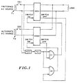
- Figure 1 is a block diagram which basically includes the concepts of the switching mechanism and is substantially described in the Short Summary of the Invention.
- a preferred AC source and an alternate AC source are provided with transformers T1, T2 and circuit breakers CB1, CB2.
- Both the preferred and alternate AC sources include a solid state switching device represented by block diagrams SSS1, SSS2.
- An interconnection from the preferred source is directed to a peak voltage detector PVD1 with an accompanying time delay TD1.
- a pair of gates U1, U2 are provided which control switching from preferred to alternate source in response to conditions of the preferred source and vice-versa on restoration of the preferred AC source to an operational mode as insured by an operational monitoring time factor.
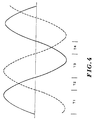
- FIG 4 a preferred and an alternate source of AC power is illustrated as being out of phase by 120 degrees. This is a typical displacement in any three phase system. Time intervals are illustrated as T1, T2, T3 and T4 (not to be confused with the transformers T1 and T2 of Figure 1). These time intervals occur between voltage zeros. As power failures are random, it is possible that control input to the preferred switch SSS1 is switched off and input to the alternate switch SSS2 is switched on during the time period T3. This would occur if the preferred source fell below its predetermined set point but was still present to some degree.
- this problem would occur on two out of three transfers. The probability will obviously change with phase displacement but will always exist except for the case when the two sources are in phase.
- This problem is eliminated by the applicant's invention with an electrical interlock provided by current detection, which results in providing that a solid state switch from which the control input has been removed is in fact off. In other words, no current is being transferred from the preferred source when the off switches, connecting the load to the alternate AC source, turn on.
- the electrical interlock provided by zero current detection accomplishes this and is a unique feature of the applicant's switching technique.
- Figures 2 and 3 In the schematic illustrations of Figures 2 and 3, various components, gates and the like are set forth and described. In Figures 2 and 3 and the correlated description, certain pin contacts of the various gates and inverters are provided to present a thorough description of the operation of the unit. In addition to the illustration of Figure 2, Figure 3 is provided to illustrate the logic analysis of provisional power to insure the actuation of the various circuit components for switching. Points A, B, C and D illustrate connective points of Figures 2 and 3 for continuity of the drawings.
- both hot and neutral lines from the preferred power source and the alternate power source are provided with silicon controlled rectifiers (SCR) K1, K2, K3, K4 respectively, with a zero current detector ZCD1, ZCD2 arranged about the high potential lead from each of the sources.
- Current detectors ZCD1 and ZCD2 are inter-connected to sensors S1, S2. It is the zero current detectors that insure that SCRs, K1, K2 are "off” before energization of SCRs, K3, K4 and vice-versa.
- Peak voltage detectors PVD1 and PVD2 as well as gates U1 and U2 are also interconnected to the preferred power and alternate power lines.
- Instantaneous value of voltage from the preferred source is initially set by P1 which is also supplied to peak voltage detector U1. If the set point is exceeded, the voltage is considered normal for operation. In this condition the output of U1 switches off when the predetermined set point is exceeded.
- a lower threshhold of voltage is set by selection of resistance R3. This may be, for example, 50% of the rated or normal voltage. When the voltage falls below this lower threshhold level as determined by U1 the output of U1 switches on. This output is integrated by the adjusted RC circuit consisting of rheostat P2 and capacitor C1 which thereafter controls the input of a triggering device U3. This triggering device U3 is commonly referred to as a Schmitt trigger.
- timer which is referred to as a power-fail timer, PFT.
- PFT power-fail timer
- U1 switches off and resets the timer so trigger U3 remains off.
- the U3 output With no input, the U3 output, being inverted, is high and provides an enabling input to gate U4 at pin 10.
- Timer U6 (555) is inactive at this time as it only responds to negative-going output from U3 pin 4. With timer U6 off, gate U3 pin 12 is high at gate U4 pin 2 thus enabling the same, since the input to pin 1 is also high.
- the junctions turn on at the next voltage zero to complete the delivery of power from the preferred source to the load. Also, at this time the load current is sensed by zero current detector ZCD1 and its sensor S1 whose low output now holds gate U9 at pin 4 off thus holding off control input to alternate power source SCRs, K3, K4.
- pin 4 of trigger 3 goes high thus enabling gate 9, pin 5 through pin 5 of gate 8.
- the combination of ZCD1, S1 output remains low which provides an inhibiting input at pin 4 of gate U9.
- SCRs K1, K2 turn off on the next current zero as detected by ZCD1 and transmitted by S1.
- gate 9 is enabled and gate 9, pin 6 goes high with gate U7, pin 12 going low.
- This delay situation in the transfer back to the preferred source is to insure that the preferred source is stabilized above a set point before the actual transfer occurs. This is a common feature of transfer switches so as to prevent nuisance switching, erratic voltage and the like.
- ZVT zero voltage turn on
- Devices are also available in a random turn on version. Such a random version turns on instantly when the control input is energized and thus reduces the actual time the load is without voltage. Applicant's mechanism and the principles thereof are applicable to either of the types described and the mode of operation of the SCRs is not a pertinent aspect of the invention.
- the alternate power source is also connected to a peak voltage detector U2 with a set level as determined by P3.
- the output from this peak voltage detector U2 is transmitted through trigger U3, pin 13 through U7, pin 11 to the output module OM4, LED, indicating the presence of the alternate power source.
- the attendant will know through the proper output modules whether the load is on the preferred source or on the alternate source, will also know whether the preferred or alternate is present for switching and will also know whether there is a fault in either of the logic supplies.
- FIG. 5 An additional feature of the applicant's concept related to user convenience and monitoring of the transfer mechanism is illustrated in Figure 5. This illustration relates to the unique method of generating a signal with accompanying alerting mechanisms should any of the solid state switch junctions become shorted.
- Figure 5 illustrates the solid state switches employed in transferring the preferred sources as PL1, P12. Assuming these switches to be of the zero voltage turn on type with control input energized, the following occurs:
- the preferred junctions are switched on with the alternate power source present but its junctions switched off. Should one of the preferred junctions short no effect of normal operation would occur and as the alternate switches are off, the preferred source would continue to supply the load.
- Applicant's description and disclosure obviously provides for an operational as well as a descriptive statement of elements necessary to provide a completely operative connect and interconnect for delivering power to a load from a preferred or alternate power source.
Landscapes
- Business, Economics & Management (AREA)
- Emergency Management (AREA)
- Engineering & Computer Science (AREA)
- Power Engineering (AREA)
- Stand-By Power Supply Arrangements (AREA)
Applications Claiming Priority (1)
| Application Number | Priority Date | Filing Date | Title |
|---|---|---|---|
| US07/467,946 US5138184A (en) | 1990-01-22 | 1990-01-22 | Solid state static power transfer mechanism |
Publications (1)
| Publication Number | Publication Date |
|---|---|
| EP0570636A1 true EP0570636A1 (fr) | 1993-11-24 |
Family
ID=23857800
Family Applications (1)
| Application Number | Title | Priority Date | Filing Date |
|---|---|---|---|
| EP92304518A Withdrawn EP0570636A1 (fr) | 1990-01-22 | 1992-05-19 | Dispositif statique à l'état solide pour transfert d'énergie |
Country Status (2)
| Country | Link |
|---|---|
| US (1) | US5138184A (fr) |
| EP (1) | EP0570636A1 (fr) |
Cited By (2)
| Publication number | Priority date | Publication date | Assignee | Title |
|---|---|---|---|---|
| FR2804551A1 (fr) * | 2000-02-02 | 2001-08-03 | Mitsubishi Electric Corp | Dispositif de transfert d'alimentation |
| CN104011966A (zh) * | 2011-12-28 | 2014-08-27 | 三菱日立电力系统株式会社 | 电力供给装置及电力供给切换方法 |
Families Citing this family (32)
| Publication number | Priority date | Publication date | Assignee | Title |
|---|---|---|---|---|
| US5138184A (en) * | 1990-01-22 | 1992-08-11 | Powertrol, Inc. | Solid state static power transfer mechanism |
| US5386147A (en) * | 1991-04-01 | 1995-01-31 | Leland Electrosystems Inc. | Aerospace power control system for monitoring and reliably transferring power buses |
| US6150736A (en) * | 1992-02-28 | 2000-11-21 | Brill; Kenneth G. | Redundant electrical power source, distribution and consumption system |
| US5289046A (en) * | 1992-06-10 | 1994-02-22 | Digital Equipment Corporation | Power converter with controller for switching between primary and battery power sources |
| US5679985A (en) * | 1992-09-23 | 1997-10-21 | International Business Machines Corporation | Power supply with automatic recovery system |
| US5635827A (en) * | 1994-11-18 | 1997-06-03 | Watlow Electric Manufacturing Company | Power control system |
| US5644175A (en) * | 1995-03-28 | 1997-07-01 | Cyberex, Inc. | Static switch method and apparatus |
| US5814904A (en) * | 1995-03-28 | 1998-09-29 | Cyberex, Inc. | Static switch method and apparatus |
| US5770897A (en) * | 1996-09-16 | 1998-06-23 | Abb Power T&D Company Inc. | Hybrid solid state switch |
| US7269034B2 (en) | 1997-01-24 | 2007-09-11 | Synqor, Inc. | High efficiency power converter |
| US5999417A (en) | 1997-01-24 | 1999-12-07 | Fische, Llc | High efficiency power converter |
| JP3224756B2 (ja) * | 1997-04-16 | 2001-11-05 | インターナショナル・ビジネス・マシーンズ・コーポレーション | 内部acアダプタ付き電源装置、及び携帯型電子機器 |
| US6011327A (en) * | 1997-12-19 | 2000-01-04 | International Business Machines Corporation | AC transfer switch |
| US6031298A (en) * | 1997-12-19 | 2000-02-29 | International Business Machines Corporation | 2N redundant power system and method using cross-coupled AC power transfer |
| KR100321976B1 (ko) | 1997-12-29 | 2002-05-13 | 윤종용 | 인텔프로세서를위한오류허용전압조절모듈회로 |
| US6560128B1 (en) * | 1999-02-12 | 2003-05-06 | Satcon Power Systems Canada Ltd. | Ferroresonance-suppressing static transfer switch |
| US6621180B2 (en) * | 2001-04-20 | 2003-09-16 | International Business Machines Corporation | Method and system for maintaining full power during a power interruption in a multiple power supply system |
| US6630753B2 (en) * | 2001-10-29 | 2003-10-07 | International Business Machines Corporation | Low cost redundant AC to DC power supply |
| US7129599B2 (en) * | 2002-10-15 | 2006-10-31 | Soft Switching Technologies Corporation | Dual feed power supply systems with enhanced power quality |
| WO2008092122A2 (fr) * | 2007-01-25 | 2008-07-31 | Cru Acquisition Group, Llc. | Unité de transfert d'alimentation en courant alternatif ininterruptible |
| US7932635B2 (en) * | 2007-04-27 | 2011-04-26 | Liebert Corporation | Transfer switch system with neutral current management |
| TWI401868B (zh) * | 2008-11-20 | 2013-07-11 | Spi Electronic Co Ltd | Active output compensation circuit |
| US8232680B2 (en) * | 2009-12-21 | 2012-07-31 | International Business Machines Corporation | Selecting a single AC source for a switching power supply |
| US8558408B2 (en) * | 2010-09-29 | 2013-10-15 | General Electric Company | System and method for providing redundant power to a device |
| US8941265B2 (en) | 2010-10-20 | 2015-01-27 | Hamilton Sundstrand Corporation | Minimal interruption DC power supply |
| EP2595268B1 (fr) * | 2011-11-17 | 2017-01-04 | Hamilton Sundstrand Corporation | Alimentation électrique CC à interruption minimale |
| US9831675B2 (en) | 2012-12-27 | 2017-11-28 | General Electric Company | System for common redundant bypass feed paths in uninterruptible power supplies |
| BR112015024546A2 (pt) | 2013-03-27 | 2017-07-18 | Flexenclosure Ab Publ | aparelho de fonte de alimentação, sistema de fonte de alimentação, e, método de comutação de alimentação |
| US10199950B1 (en) | 2013-07-02 | 2019-02-05 | Vlt, Inc. | Power distribution architecture with series-connected bus converter |
| CN108475993B (zh) * | 2015-12-28 | 2020-08-14 | 跑道能源有限责任公司 | 电力恢复系统和方法 |
| GB2626766A (en) * | 2023-02-01 | 2024-08-07 | Eaton Intelligent Power Ltd | Switch arrangement and method for operating a switch arrangement |
| US12267007B1 (en) * | 2023-12-01 | 2025-04-01 | L3Harris Technologies, Inc. | Fault-tolerant control for static transfer switch system |
Citations (3)
| Publication number | Priority date | Publication date | Assignee | Title |
|---|---|---|---|---|
| EP0064085A1 (fr) * | 1981-04-30 | 1982-11-10 | Michele Cerciello | Circuit de commande pour un dispositif pour commuter d'une tension alternative à une autre |
| US4879624A (en) * | 1987-12-24 | 1989-11-07 | Sundstrand Corporation | Power controller |
| US5138184A (en) * | 1990-01-22 | 1992-08-11 | Powertrol, Inc. | Solid state static power transfer mechanism |
Family Cites Families (3)
| Publication number | Priority date | Publication date | Assignee | Title |
|---|---|---|---|---|
| US3932764A (en) * | 1974-05-15 | 1976-01-13 | Esb Incorporated | Transfer switch and transient eliminator system and method |
| US4484084A (en) * | 1983-08-22 | 1984-11-20 | Ncr Corporation | Power MOSFET transfer switch |
| US4761563A (en) * | 1987-10-27 | 1988-08-02 | International Business Machines Corporation | Asynchronous multiphase switching gear |
-
1990
- 1990-01-22 US US07/467,946 patent/US5138184A/en not_active Expired - Lifetime
-
1992
- 1992-05-19 EP EP92304518A patent/EP0570636A1/fr not_active Withdrawn
Patent Citations (3)
| Publication number | Priority date | Publication date | Assignee | Title |
|---|---|---|---|---|
| EP0064085A1 (fr) * | 1981-04-30 | 1982-11-10 | Michele Cerciello | Circuit de commande pour un dispositif pour commuter d'une tension alternative à une autre |
| US4879624A (en) * | 1987-12-24 | 1989-11-07 | Sundstrand Corporation | Power controller |
| US5138184A (en) * | 1990-01-22 | 1992-08-11 | Powertrol, Inc. | Solid state static power transfer mechanism |
Cited By (4)
| Publication number | Priority date | Publication date | Assignee | Title |
|---|---|---|---|---|
| FR2804551A1 (fr) * | 2000-02-02 | 2001-08-03 | Mitsubishi Electric Corp | Dispositif de transfert d'alimentation |
| CN104011966A (zh) * | 2011-12-28 | 2014-08-27 | 三菱日立电力系统株式会社 | 电力供给装置及电力供给切换方法 |
| CN104011966B (zh) * | 2011-12-28 | 2016-09-28 | 三菱日立电力系统株式会社 | 电力供给装置及电力供给切换方法 |
| US9673624B2 (en) | 2011-12-28 | 2017-06-06 | Mitsubishi Hitachi Power Systems, Ltd. | Power supply device and power supply switching method |
Also Published As
| Publication number | Publication date |
|---|---|
| US5138184A (en) | 1992-08-11 |
Similar Documents
| Publication | Publication Date | Title |
|---|---|---|
| US5138184A (en) | Solid state static power transfer mechanism | |
| US4879624A (en) | Power controller | |
| US5790394A (en) | Dual AC power supply input module | |
| US7446437B2 (en) | Apparatus and method for preventing an electrical backfeed | |
| JP5059197B2 (ja) | 選択スイッチ装置、これを利用した電源供給装置、及びそのスイッチング方法 | |
| CN101931218B (zh) | 与母线连接的组件供电电流电子监控装置 | |
| US6317346B1 (en) | Redundant multiphase power supplies for common load device | |
| US6153947A (en) | Dual feed hot swap battery plant controller for power supplies | |
| US6011327A (en) | AC transfer switch | |
| US6639816B2 (en) | Power supply system with AC redundant power sources and safety device | |
| US3509357A (en) | Static transfer switching system | |
| US10804696B2 (en) | Power distribution system and method | |
| KR19990066929A (ko) | 전송 장치 및 단절 유닛 | |
| EP0471178B1 (fr) | Ensemble pour transfert d'énergie | |
| US6150792A (en) | Phase monitor | |
| US6483682B1 (en) | Electric power distribution system employing a fight-through switch | |
| US6683771B2 (en) | Electrical energy distribution system and contactor for such a system | |
| US5272387A (en) | Connecting device of an external electrical power supply source to an aircraft on the ground | |
| JPS5858834A (ja) | 静止型無効電力補償装置 | |
| CA2066935A1 (fr) | Mecanisme de transfert en technique semiconducteurs de source statique d'energie | |
| CN115568291A (zh) | 特别是用于数据中心的冗余电源及用于其运行的方法和计算机程序 | |
| JPH02206325A (ja) | 配電線保護装置 | |
| EP0378532B1 (fr) | Circuit pour empecher les retours de tension et de courant vers la ligne de distribution d'electricite dans une installation a courant fort du type a onduleur | |
| JP2786492B2 (ja) | 高圧異相電路切替装置及び同装置を用いた高圧異相電路切替方法 | |
| SU1683128A1 (ru) | Устройство дл автоматического ввода резерва в системе электроснабжени с вентильными преобразовател ми |
Legal Events
| Date | Code | Title | Description |
|---|---|---|---|
| PUAI | Public reference made under article 153(3) epc to a published international application that has entered the european phase |
Free format text: ORIGINAL CODE: 0009012 |
|
| AK | Designated contracting states |
Kind code of ref document: A1 Designated state(s): BE DE FR GB LU NL |
|
| 17P | Request for examination filed |
Effective date: 19940803 |
|
| 17Q | First examination report despatched |
Effective date: 19950307 |
|
| STAA | Information on the status of an ep patent application or granted ep patent |
Free format text: STATUS: THE APPLICATION IS DEEMED TO BE WITHDRAWN |
|
| 18D | Application deemed to be withdrawn |
Effective date: 19951201 |