EP0570652A2 - Connecteur pour fibres optiques - Google Patents
Connecteur pour fibres optiques Download PDFInfo
- Publication number
- EP0570652A2 EP0570652A2 EP92810963A EP92810963A EP0570652A2 EP 0570652 A2 EP0570652 A2 EP 0570652A2 EP 92810963 A EP92810963 A EP 92810963A EP 92810963 A EP92810963 A EP 92810963A EP 0570652 A2 EP0570652 A2 EP 0570652A2
- Authority
- EP
- European Patent Office
- Prior art keywords
- plug
- cover
- socket
- connection according
- face
- Prior art date
- Legal status (The legal status is an assumption and is not a legal conclusion. Google has not performed a legal analysis and makes no representation as to the accuracy of the status listed.)
- Granted
Links
Images



Classifications
-
- H—ELECTRICITY
- H01—ELECTRIC ELEMENTS
- H01R—ELECTRICALLY-CONDUCTIVE CONNECTIONS; STRUCTURAL ASSOCIATIONS OF A PLURALITY OF MUTUALLY-INSULATED ELECTRICAL CONNECTING ELEMENTS; COUPLING DEVICES; CURRENT COLLECTORS
- H01R13/00—Details of coupling devices of the kinds covered by groups H01R12/70 or H01R24/00 - H01R33/00
- H01R13/44—Means for preventing access to live contacts
- H01R13/447—Shutter or cover plate
- H01R13/453—Shutter or cover plate opened by engagement of counterpart
-
- G—PHYSICS
- G02—OPTICS
- G02B—OPTICAL ELEMENTS, SYSTEMS OR APPARATUS
- G02B6/00—Light guides; Structural details of arrangements comprising light guides and other optical elements, e.g. couplings
- G02B6/24—Coupling light guides
- G02B6/36—Mechanical coupling means
- G02B6/38—Mechanical coupling means having fibre to fibre mating means
- G02B6/3807—Dismountable connectors, i.e. comprising plugs
-
- G—PHYSICS
- G02—OPTICS
- G02B—OPTICAL ELEMENTS, SYSTEMS OR APPARATUS
- G02B6/00—Light guides; Structural details of arrangements comprising light guides and other optical elements, e.g. couplings
- G02B6/24—Coupling light guides
- G02B6/36—Mechanical coupling means
- G02B6/38—Mechanical coupling means having fibre to fibre mating means
- G02B6/3807—Dismountable connectors, i.e. comprising plugs
- G02B6/3833—Details of mounting fibres in ferrules; Assembly methods; Manufacture
-
- G—PHYSICS
- G02—OPTICS
- G02B—OPTICAL ELEMENTS, SYSTEMS OR APPARATUS
- G02B6/00—Light guides; Structural details of arrangements comprising light guides and other optical elements, e.g. couplings
- G02B6/24—Coupling light guides
- G02B6/36—Mechanical coupling means
- G02B6/38—Mechanical coupling means having fibre to fibre mating means
- G02B6/3807—Dismountable connectors, i.e. comprising plugs
- G02B6/3833—Details of mounting fibres in ferrules; Assembly methods; Manufacture
- G02B6/3847—Details of mounting fibres in ferrules; Assembly methods; Manufacture with means preventing fibre end damage, e.g. recessed fibre surfaces
- G02B6/3849—Details of mounting fibres in ferrules; Assembly methods; Manufacture with means preventing fibre end damage, e.g. recessed fibre surfaces using mechanical protective elements, e.g. caps, hoods, sealing membranes
-
- G—PHYSICS
- G02—OPTICS
- G02B—OPTICAL ELEMENTS, SYSTEMS OR APPARATUS
- G02B6/00—Light guides; Structural details of arrangements comprising light guides and other optical elements, e.g. couplings
- G02B6/24—Coupling light guides
- G02B6/36—Mechanical coupling means
- G02B6/38—Mechanical coupling means having fibre to fibre mating means
- G02B6/3807—Dismountable connectors, i.e. comprising plugs
- G02B6/389—Dismountable connectors, i.e. comprising plugs characterised by the method of fastening connecting plugs and sockets, e.g. screw- or nut-lock, snap-in, bayonet type
- G02B6/3893—Push-pull type, e.g. snap-in, push-on
-
- G—PHYSICS
- G02—OPTICS
- G02B—OPTICAL ELEMENTS, SYSTEMS OR APPARATUS
- G02B6/00—Light guides; Structural details of arrangements comprising light guides and other optical elements, e.g. couplings
- G02B6/24—Coupling light guides
- G02B6/36—Mechanical coupling means
- G02B6/38—Mechanical coupling means having fibre to fibre mating means
- G02B6/3807—Dismountable connectors, i.e. comprising plugs
- G02B6/381—Dismountable connectors, i.e. comprising plugs of the ferrule type, e.g. fibre ends embedded in ferrules, connecting a pair of fibres
- G02B6/3825—Dismountable connectors, i.e. comprising plugs of the ferrule type, e.g. fibre ends embedded in ferrules, connecting a pair of fibres with an intermediate part, e.g. adapter, receptacle, linking two plugs
Definitions
- the invention relates to a plug-in connection for optical fibers according to the preamble of claim 1.
- Even slight contamination can lead to transmission loss in optical plug-in connections, since glass fibers with the smallest cross-sections have to be aligned with one another at the end.
- Protective devices have therefore already been provided, with the aid of which the plug pin can be protected when the plug is not inserted.
- EP-A-22 000 shows a protective device for a plug, which could also be used for optical fibers.
- the basic principle of the protective device is that the connector pins are covered by two superimposed disks. The disks can be rotated relative to one another on a common axis and are provided with openings which lie congruently one above the other in at least one relative position and in this way release the connector pins. The connector pins can then be moved through the openings in an axis-parallel movement and inserted into the connector sockets.
- the disadvantage of this protective device is that it is only suitable for heavy connector parts with a certain outside diameter. To insert the plug part, both a rotary movement and a linear sliding movement must be carried out.
- the known device is not suitable for small plug parts, such as are used more and more in measurement technology, in communications technology or in consumer electronics.
- This object is achieved according to the invention with a plug connection which has the features in claim 1 and in claim 14.
- the cover which is movably arranged on the plug part, is a single component that can be moved by a simple linear plug movement. Complicated movements for exposing the connector pin are not necessary, but the connector pin is exposed immediately in the course of the insertion movement. This also reliably ensures that the high-precision machined and relatively sensitive connector pin is only released when it is already in the protective socket part. Among other things, this also prevents laser light, for example, emerging from the plug pin from unintentionally causing eye damage.
- the cover is preferably pivotally mounted on the plug part and it has a guide piece, the control path being at least one guide link which cooperates with the guide piece to pivot the cover.
- the cover can also be pivotally and displaceably mounted on the plug part and it can have a guide piece, the control track being at least one guide groove which interacts with the guide piece for pivoting and displacing the cover.
- This combined pivoting / sliding movement of the cover has the advantage that the cover can be accommodated in a space-saving manner within the socket part. Instead of a circular path, the outer edge back of the cover a curved path that takes up much less space.
- the combined movement of the cover can be implemented particularly easily if the guide piece has at least one joint element which rotatably and displaceably engages in a guide slot on the plug part and if it has at least one engagement member which engages in the guide groove on the socket part when the cover is closed.
- the joint element and the engaging link ensure precise guidance even with rapid movements.
- the guide piece and the guide groove advantageously cooperate in such a way that the cover is pulled back behind the plane of the end face of the plug pin in the open position. This makes it possible for the plug to be inserted into a socket part from both sides in such a way that the opened covers face each other in the same plane. It is not necessary to twist the connector by 180 ° to overlap the cover.
- the cover is preferably pivoted about 90 ° in the open position relative to the closed position. In this position, it requires relatively little space in the socket part. This applies in particular to flat covers. However, other angular positions in the open position would be conceivable.
- the cover is preferably biased into the closed position under spring tension so that it always closes reliably when the plug part is unplugged.
- the spring preload can be generated in very different ways. It would be conceivable for a helical spring mounted on the swivel axis, a spring clip or also a bearing socket which is designed such that it exerts a spring action in a certain direction due to the elasticity of the material.
- the cover can also be biased into the closed position with a spring cam which resiliently presses against the end face and / or against the long side of the plug part.
- a spring cam has the advantage that it can be formed in one piece with the cover and that therefore no additional parts are required for the spring preload.
- the cover can be essentially disc-shaped or can also be curved in an arc. In the latter case, it is possible for it to be slidably mounted on the plug part on an arc path.
- the cover can either press directly against the end face of the connector pin or it can be pressed against an end part surrounding the connector pin.
- the inside of the cover facing the plug end is at least in the area of the plug pin beveled relative to the optical axis of the optical waveguide in the plug pin such that feedback of light into the optical waveguide is prevented.
- control track will preferably be arranged on the socket part for reasons of space.
- control track for example a guide groove or a guide link
- a control element for example in the form of a control cam
- a connector part 1 is shown, the connector housing 13 has a substantially approximately rectangular cross section.
- the plug pin 2 is held in a pin holder 10 which has an end part 9 which has a bore, the inner wall of which surrounds the plug pin.
- the actual connector housing 13 is axially displaceable on the pin holder 10 by a small distance.
- a locking bar 11 is arranged on each of two opposite sides, which is approximately at the same height as a ramp 20 belonging to the plug housing 13.
- a guide piece 8 is arranged on the cover 6 on one side.
- the guide piece has an approximately nose-like configuration here.
- FIG. 2 shows a socket part 3 for receiving the plug part 1.
- the socket part essentially has a hollow box-shaped socket housing 16 which is provided with a flange 14 for attachment to a housing wall.
- the actual socket 4 for receiving the plug pin or the plug pins is held in a socket holder 21.
- the socket is preferably held in a floating manner in the socket holder.
- resilient tongues 15 are arranged, at the end of which a pawl 12 is seated.
- a control track is provided on an inside of the socket housing, which here has the form of parallel guide links 7.
- the socket holder 21 is held in the socket housing 16 with the aid of a holding wall 22.
- the holding wall is dimensioned such that it leaves an opening 23, 23 'at the top and bottom, which extends over the entire width. These openings serve to receive the opened cover 6 of an inserted plug part 1, as subsequently is still described.
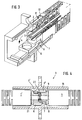
- the plug connection with the plug part inserted can be seen in FIG. 3.
- the guide piece 8 of the cover 6 hits the guide link 7, the cover 6 being folded down in the direction of arrow a.
- the actual plug socket 4 is not shown in FIG. 3.
- the plug pin 2 penetrates into the plug socket 4 in the course of the insertion movement, in which its end face 5 meets the end face of an adjacent plug pin.
- the pawl 12 engages behind the locking bar 11, as a result of which the plug part is secured in the socket part.
- the exemplary embodiment shown is a so-called push-and-pull lock.
- This latching device can only be released if the tensile force acts on the plug housing 13 to pull out the plug part.
- the connector housing 13 slides back somewhat relative to the pin holder 10, the ramp 20 lifting the pawl 12 so that the locking bar 11 is released (FIG. 1).
- the tensile force acts on the cable (not shown here) and thus on the pin holder 10, the pawl 12 cannot be disengaged.
- This type of locking on optical connectors is already known per se.
- the fixing of the plug part to the socket part could also in other ways, e.g. with the help of a union nut.
- the cover 6 is preferably made of plastic material and designed such that it can only be snapped into the end part 9.
- the lid 6 does not necessarily have to be pivoted back over the guide backdrop. It is readily conceivable that the closing movement only takes place by springback with the aid of a suitable spring element.
- FIG. 4 schematically shows a socket part 3 according to FIG. 2, into which a plug part 1, 1 'is inserted from both sides.
- this socket part not only has a pair of guide slots 7 on the underside, but also a pair of guide slots 7 'on the top, symmetrically offset with respect to the plane of contact between the two connector pins.
- the plug part 1 ' is inserted rotated by 180 ° relative to the plug part 1, the outer contour of the plug housing and the inner contour of the socket housing being designed such that the two plug parts can only be inserted in this position.
- the two covers 6 and 6 'of the plug parts 1 and 1' overlap in the inserted state and slide through the openings 23 and 23 'according to FIG. 2.
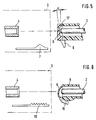
- Figure 5 shows again schematically a part of the socket 4 and the guide link 7 in the socket part 3 and the cover 6 with the guide piece 8.
- the cover is cap-shaped, the cover inner wall 17 is chamfered at an angle ⁇ relative to the plug end face in order to a feedback of Avoid light through reflection.
- the angle ⁇ can be, for example, approximately 7 °.
- the geometric relationship between the socket 4, the guide link 7 and the cover 6 must be selected such that the cover 6 is opened in good time before the socket 4 is reached becomes. The cover then partially slides under the socket 4.
- FIG. 6 An alternative embodiment of the invention is shown schematically in Figure 6.
- the control path here does not consist of a guide link, but of a rack section 18.
- the cover 6 is curved in an arcuate manner and is displaceably mounted on the circular part on the end part 9, for example in lateral grooves or the like.
- the cover has a toothed segment 19, which meshes with the toothed rack section 18 when the plug part is inserted into the socket part. The cover 6 is pushed open and the plug pin 2 is exposed before it reaches the socket 4.
- the lid closure according to the invention can not only be implemented on connector parts with a square cross section.
- Plug parts with a round cross section can also be provided in the same or similar manner with a movable cover, which is then also essentially round.
- the socket part does not necessarily have to be a separate component. It would be conceivable that the socket part is directly part of the one plug part.
- FIGS. 7 to 12 show a further alternative exemplary embodiment of the invention, in which the cover performs a combined pivoting and sliding movement.
- the fastening and unlocking of the plug part in the socket part is also solved here.
- the same components have the same reference numerals as in the previous embodiments.
- FIGS. 7 and 8 show a plug part 1, which essentially also has an approximately rectangular plug housing 13.
- the pin holder with the connector pin 2 is not axially displaceable, but is held firmly in the connector housing.
- the connector housing also carries a locking bar 11, on which it can be latched in the socket part.
- An unlocking lever 25 serves for unlocking, the function of which will be explained in more detail below.
- the cover 6 has a guide piece 8 in the form of 2 wings running at right angles to the cover 6.
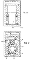
- Articulated cams 28 (FIG. 12) are arranged on the inside of these wings, which are not visible in the figure, and each engage in a guide slot 27 on the side wall of a prismatic guide strip 26.
- the slots 27 run upward in the area of the locking strips 11 so that the articulated cams can be inserted.
- Control cams 29 are arranged on the outside of the vanes 42 at a distance from the articulated cams 28. These control cams serve to move the cover 6 in the socket part with the aid of guide grooves 30 (FIG. 12).
- a spring cam 24 is arranged between the wings 42 and presses against the end face of the guide bar 26.
- FIG. 8 shows the plug part 1 with the cover 6 open.
- the cover 6 normally occupies this position only within the socket part. Of course, it is also possible to open the lid manually and push it back.
- the cover 6 performs a pivoting movement about the axes of the articulated cams 28 and at the same time the articulated cams slide in the guide slots 27 in the direction of arrow b backwards against the locking bar 11.
- the cover 6 is withdrawn behind the plane of the end face 5 of the plug pin 2.
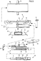
- FIG 9 shows the individual parts of a connector with the individual components and Figure 10 shows a cross section through such a connector.
- the socket part 3 is constructed in two parts and consists of the outer socket housing 16 with the flange 14 and the inner socket housing 41. As can be seen in particular from FIGS. 11 and 12, the socket part also has an essentially box-shaped cross section.
- the inner socket housing 41 can be inserted into the outer socket housing 16, whereby it is secured on both sides with a snap-on frame 31.
- the inner socket housing 41 is constructed approximately symmetrically and has lateral guide grooves 30 for receiving and guiding the control cams 29 on the guide piece of the cover.
- a resilient tongue 15 with a pawl 12 is provided to hold and secure the plug part.
- Lateral grooves 43 on the inner wall of the inner socket housing 41 can accommodate the side strips 44 on the plug housing 13. In this way, the plug part cannot be tilted in the socket part.
- the socket holder 21 with the actual socket 4 for the plug pins is inserted from below through an opening into the inner socket housing 41. After sliding the outer socket housing 16, the socket holder 21 is secured.
- a two-armed leaf spring 33 is also clamped beneath the socket holder 21 and pretensions a protective flap 32 with its free ends.
- the protective flap 32 is articulated between the inner socket housing 41 and the outer socket housing 16.
- the plug part 1 consists essentially of the plug housing 13, to which the cover 6 and the unlocking lever 25 are attached.
- the unlocking lever 25 is engaged with its articulated cams 35 in openings 45 in the plug housing 13.
- a lever arm 34 engages under the pawl 12 on the socket part so that it can be raised for unlocking.
- the inside of the plug housing 13 is partially designed as a spline hub 34.
- the pin holder 10 has a section which is designed as a spline shaft 36.
- Individual wedges 39 on a rear section of the pin holder snap into the shoulders 40 of the spline hub, so that the pin holder 10 can be pushed into the plug housing 13.
- the spline shaft / spline hub connection serves to determine the relative angular position of the connector pin. With six individual wedges or keyways, there are a total of six possible angular positions of the plug pin in the connector housing 13. With respect to the central axis of the optical waveguide, the most optimal position is selected in each case by a measurement process, so that the most favorable tolerance pair with respect to the eccentricity of the optical waveguide always meets within a plug connection.
- the pin holder 10 is preferably made in one piece from plastic material and has a resilient section 38, so that the plug pin 2 is axially cushioned relative to the plug housing 13.
- FIG. 10 shows the socket part 3 in the assembled state, which is fastened, for example, to a housing wall 46.
- a connector part 1 is already inserted and locked on the right-hand side, the cover 6 being arranged axially parallel between the guide strip 26 of the connector housing and the tongue 15 of the inner socket housing 41.
- the plug pin 2 penetrates into the socket 4. In this position, too Protective flap 32 pressed axially parallel downward against the force of the leaf spring 33.
- the front section of a connector part 1 is shown, which is inserted into the connector.
- the cover 6 is initially still in its closed position.
- the control cams 29 engage in the guide grooves 30, which is somewhat facilitated by a wedge-shaped extension.
- the guide grooves 30 have a path that first runs parallel to the axis, then obliquely against the central axis of the plug connection and then again runs parallel to the axis.
- the control cams 29 are pressed down, which initiates the pivoting movement of the cover 6.
- An intermediate position of the cover 6 in this oblique section is indicated by dash-dotted lines.
- the movement of the cover relative to the connector housing 13 is delayed, so that the cover 6 is pulled backwards.
- the protective flap 32 is also pressed down continuously in the course of the insertion movement until it assumes its end position.
- the pawl 12 engages behind the locking bar 11.
Landscapes
- Physics & Mathematics (AREA)
- General Physics & Mathematics (AREA)
- Optics & Photonics (AREA)
- Mechanical Coupling Of Light Guides (AREA)
Priority Applications (4)
| Application Number | Priority Date | Filing Date | Title |
|---|---|---|---|
| AU38490/93A AU658999B2 (en) | 1992-05-20 | 1993-05-10 | Plug connector for optical fibers |
| US08/059,359 US5348487A (en) | 1992-05-20 | 1993-05-11 | Plug connector for optical fibers |
| JP11852393A JP3258760B2 (ja) | 1992-05-20 | 1993-05-20 | 光ファイバ用のプラグ・コネクタ |
| JP2001307209A JP3681672B2 (ja) | 1992-05-20 | 2001-10-03 | 光ファイバ用プラグコネクタ |
Applications Claiming Priority (2)
| Application Number | Priority Date | Filing Date | Title |
|---|---|---|---|
| CH1625/92 | 1992-05-20 | ||
| CH162592 | 1992-05-20 |
Publications (3)
| Publication Number | Publication Date |
|---|---|
| EP0570652A2 true EP0570652A2 (fr) | 1993-11-24 |
| EP0570652A3 EP0570652A3 (fr) | 1993-12-01 |
| EP0570652B1 EP0570652B1 (fr) | 1996-04-03 |
Family
ID=4214821
Family Applications (1)
| Application Number | Title | Priority Date | Filing Date |
|---|---|---|---|
| EP92810963A Expired - Lifetime EP0570652B1 (fr) | 1992-05-20 | 1992-12-08 | Connecteur pour fibres optiques |
Country Status (2)
| Country | Link |
|---|---|
| EP (1) | EP0570652B1 (fr) |
| DE (1) | DE59205913D1 (fr) |
Cited By (32)
| Publication number | Priority date | Publication date | Assignee | Title |
|---|---|---|---|---|
| EP0642044A1 (fr) * | 1993-09-02 | 1995-03-08 | State of Israel Ministry of Defence Raphael Armament Development Authority | Appareil de ligne terminal en particulier émettant des signaux, ensemble de connexion |
| EP0613030A3 (fr) * | 1993-02-24 | 1995-06-21 | Sumitomo Wiring Systems | Connecteur fibre-optique. |
| EP0665454A1 (fr) * | 1994-02-01 | 1995-08-02 | Hirose Electric Co., Ltd. | Connecteur |
| EP0697607A1 (fr) * | 1994-08-01 | 1996-02-21 | Molex Incorporated | Ensemble de composants optiques avec claper mobile de protection |
| EP0823649A1 (fr) * | 1996-08-08 | 1998-02-11 | Diamond S.A. | Elément de connecteur pour connexion optique |
| EP0893718A1 (fr) * | 1997-07-21 | 1999-01-27 | Diamond SA | Douille en particulier pour une connexion optique et connecteur pour fibres optiques |
| WO1998053347A3 (fr) * | 1997-05-20 | 1999-04-01 | Adc Telecommunications Inc | Connecteur et adaptateur de fibres |
| EP1004911A1 (fr) * | 1998-11-23 | 2000-05-31 | Diamond SA | Elément de prise femelle pour un connecteur optique |
| EP0962799A3 (fr) * | 1998-06-05 | 2000-08-30 | Hirose Electric Co., Ltd. | Connecteur optique avec volet d'obturation |
| US6142676A (en) * | 1997-05-20 | 2000-11-07 | Adc Telecommunications, Inc. | Fiber connector and adaptor |
| EP1072919A1 (fr) * | 1999-07-26 | 2001-01-31 | Diamond SA | Fiche mâle pour connexion optique |
| EP1072917A1 (fr) * | 1999-07-26 | 2001-01-31 | Diamond SA | Connecteur avec clapet de protection pour connexion à fibre optique |
| WO2002071122A1 (fr) * | 2001-03-01 | 2002-09-12 | Huber+Suhner Ag | Système de connecteur enfichable à fibre optique |
| EP1331499A1 (fr) * | 2002-01-25 | 2003-07-30 | Diamond S.A. | Connecteur optique |
| WO2003104870A1 (fr) * | 2002-06-06 | 2003-12-18 | Huber+Suhner Ag | Systeme de connexion optique par enfichage |
| DE19742932B4 (de) * | 1996-09-30 | 2005-02-10 | The Whitaker Corp., Wilmington | Adapter für Lichtwellenleiterstecker |
| DE102004009218A1 (de) * | 2004-02-26 | 2005-10-20 | Winter & Ibe Olympus | Kupplungsverbindung eines Lichtleiteranschlusskabels mit einer Endoskopoptik |
| EP1598685A1 (fr) * | 2004-05-21 | 2005-11-23 | Neutrik Aktiengesellschaft | Dispositif pour un raccordement optique enfichable |
| US7283718B2 (en) | 2002-05-14 | 2007-10-16 | Huber+Suhner Ag | Optical connector with protective cover and leaf spring |
| EP1947493A1 (fr) | 2007-01-16 | 2008-07-23 | Reichle & De-Massari AG | Système de connecteur à fiches et dispositif de protection pour connecteurs à fiches optiques |
| DE102007053415A1 (de) | 2007-11-09 | 2009-05-14 | Robert Bosch Gmbh | Faseroptisches Verbindersystem |
| US20110150396A1 (en) * | 2009-12-21 | 2011-06-23 | Hon Hai Precision Industry Co., Ltd. | Optical fiber connector |
| EP2362254A1 (fr) * | 2010-02-22 | 2011-08-31 | Sanwa Denki Kogyo Co., Ltd. | Fiche de connecteur optique avec obturateur |
| CN102262270A (zh) * | 2011-07-31 | 2011-11-30 | 中航光电科技股份有限公司 | 带有保护盖的光纤连接器插头 |
| EP2672301A1 (fr) | 2012-06-07 | 2013-12-11 | Diamond SA | Connecteur à fiches |
| DE102013103173A1 (de) * | 2013-03-27 | 2014-10-02 | Reichle & De-Massari Ag | Schutzvorrichtung |
| EP3246737A1 (fr) | 2016-05-18 | 2017-11-22 | Dätwyler Cabling Solutions AG | Élément de couplage de fibre optique et procédé de couplage associé |
| EP3218968B1 (fr) * | 2014-11-11 | 2020-06-10 | Huber+Suhner Ag | Ensemble connecteur |
| CN113296193A (zh) * | 2020-02-21 | 2021-08-24 | 立佳兴业股份有限公司 | 光学连接器及其光学连接器模块 |
| CN114690330A (zh) * | 2022-03-04 | 2022-07-01 | 上海航天科工电器研究院有限公司 | 一种防尘od正交光连接器 |
| WO2023093272A1 (fr) * | 2021-11-29 | 2023-06-01 | 宁德时代新能源科技股份有限公司 | Premier connecteur, batterie, ensemble connecteur et dispositif électrique |
| CN119481827A (zh) * | 2025-01-17 | 2025-02-18 | 东莞市信翰精密工业有限公司 | 一种多通道射频连接器的固定与拆卸装置 |
Families Citing this family (6)
| Publication number | Priority date | Publication date | Assignee | Title |
|---|---|---|---|---|
| US6004147A (en) * | 1993-09-02 | 1999-12-21 | State Of Israel, Ministry Of Defence, Etc. | Line terminal particularly signal transmitter, connector assembly |
| EP0977062B1 (fr) * | 1998-07-27 | 2002-07-03 | Huber & Suhner Ag | Prise de connexion pour des guides d'ondes lumineuses |
| DE19901447C2 (de) * | 1999-01-15 | 2001-03-22 | Tyco Electronics Logistics Ag | Steckverbindung für Lichtwellenleiter |
| DE19919591C2 (de) * | 1999-04-29 | 2001-12-20 | Tyco Electronics Logistics Ag | Steckverbindung für Lichtwellenleiter |
| US6422763B1 (en) | 2000-05-04 | 2002-07-23 | Delphi Technologies, Inc. | Fiber optic cable for connection to a mating connector |
| DE102013207510A1 (de) | 2013-04-25 | 2014-10-30 | Robert Bosch Gmbh | Elektronische Komponente |
Family Cites Families (6)
| Publication number | Priority date | Publication date | Assignee | Title |
|---|---|---|---|---|
| CA1235319A (fr) * | 1981-12-21 | 1988-04-19 | Maurus C. Logan | Obturateur mobile pour organes d'optique |
| US4779950A (en) * | 1984-04-03 | 1988-10-25 | Thomas & Betts Corporation | Connection apparatus for optical fibers |
| DE3604764A1 (de) * | 1986-02-14 | 1987-08-20 | Dynamit Nobel Ag | Elektrische steckverbindung |
| US4775327A (en) * | 1987-02-17 | 1988-10-04 | Amphenol Corporation | Connector with automatic protection cap |
| US4913514A (en) * | 1988-11-22 | 1990-04-03 | Advanced Optical Systems | Fiber optic connector |
| FR2663755B1 (fr) * | 1990-06-21 | 1992-09-18 | Radiall Sa | Connecteur pour fibres optiques a verrouillage et deverrouillage rapides. |
-
1992
- 1992-12-08 EP EP92810963A patent/EP0570652B1/fr not_active Expired - Lifetime
- 1992-12-08 DE DE59205913T patent/DE59205913D1/de not_active Expired - Lifetime
Cited By (59)
| Publication number | Priority date | Publication date | Assignee | Title |
|---|---|---|---|---|
| EP0613030A3 (fr) * | 1993-02-24 | 1995-06-21 | Sumitomo Wiring Systems | Connecteur fibre-optique. |
| EP0642044A1 (fr) * | 1993-09-02 | 1995-03-08 | State of Israel Ministry of Defence Raphael Armament Development Authority | Appareil de ligne terminal en particulier émettant des signaux, ensemble de connexion |
| EP0665454A1 (fr) * | 1994-02-01 | 1995-08-02 | Hirose Electric Co., Ltd. | Connecteur |
| EP0697607A1 (fr) * | 1994-08-01 | 1996-02-21 | Molex Incorporated | Ensemble de composants optiques avec claper mobile de protection |
| EP0823649A1 (fr) * | 1996-08-08 | 1998-02-11 | Diamond S.A. | Elément de connecteur pour connexion optique |
| DE19742932B4 (de) * | 1996-09-30 | 2005-02-10 | The Whitaker Corp., Wilmington | Adapter für Lichtwellenleiterstecker |
| EP1331496A3 (fr) * | 1997-05-20 | 2003-09-17 | ADC Telecommunications, Inc. | Connecteur et adaptateur de fibres |
| US8186890B2 (en) | 1997-05-20 | 2012-05-29 | Adc Telecommunications, Inc. | Fiber connector and adapter |
| US5984531A (en) * | 1997-05-20 | 1999-11-16 | Adc Telecommunications, Inc. | Fiber connector and adapter |
| KR100575911B1 (ko) * | 1997-05-20 | 2006-05-02 | 에이디씨 텔레커뮤니케이션스 인코포레이티드 | 섬유 커넥터 및 어댑터 |
| US6076973A (en) * | 1997-05-20 | 2000-06-20 | Adc Telecommunications, Inc. | Fiber connector and adapter |
| US7246950B2 (en) | 1997-05-20 | 2007-07-24 | Adc Telecommunications, Inc. | Fiber connector and adapter |
| US6142676A (en) * | 1997-05-20 | 2000-11-07 | Adc Telecommunications, Inc. | Fiber connector and adaptor |
| US7384201B2 (en) | 1997-05-20 | 2008-06-10 | Adc Telecommunications, Inc. | Fiber connector and adapter |
| US9383524B2 (en) | 1997-05-20 | 2016-07-05 | Commscope Technologies Llc | Fiber connector and adapter |
| US6296398B1 (en) | 1997-05-20 | 2001-10-02 | Adc Telecommunications, Inc. | Fiber connector and adapter |
| US8870466B2 (en) | 1997-05-20 | 2014-10-28 | Adc Telecommunications, Inc. | Fiber connector and adapter |
| WO1998053347A3 (fr) * | 1997-05-20 | 1999-04-01 | Adc Telecommunications Inc | Connecteur et adaptateur de fibres |
| US7118288B2 (en) | 1997-05-20 | 2006-10-10 | Adc Telecommunications, Inc. | Fiber connector and adapter |
| US7874738B2 (en) | 1997-05-20 | 2011-01-25 | Adc Telecommunications, Inc. | Fiber connector and adapter |
| US7654749B2 (en) | 1997-05-20 | 2010-02-02 | Adc Telecommunications, Inc. | Fiber connector and adapter |
| US7503702B2 (en) | 1997-05-20 | 2009-03-17 | Adc Telecommunications, Inc. | Fiber connector and adapter |
| US6910807B2 (en) | 1997-05-20 | 2005-06-28 | Adc Telecommunications, Inc. | Fiber connector and adapter |
| EP0893718A1 (fr) * | 1997-07-21 | 1999-01-27 | Diamond SA | Douille en particulier pour une connexion optique et connecteur pour fibres optiques |
| EP0893716A1 (fr) * | 1997-07-21 | 1999-01-27 | Diamond S.A. | Douille en particulier pour une connexion optique et connecteur pour fibres optiques |
| EP0962799A3 (fr) * | 1998-06-05 | 2000-08-30 | Hirose Electric Co., Ltd. | Connecteur optique avec volet d'obturation |
| EP1004911A1 (fr) * | 1998-11-23 | 2000-05-31 | Diamond SA | Elément de prise femelle pour un connecteur optique |
| EP1072919A1 (fr) * | 1999-07-26 | 2001-01-31 | Diamond SA | Fiche mâle pour connexion optique |
| EP1072917A1 (fr) * | 1999-07-26 | 2001-01-31 | Diamond SA | Connecteur avec clapet de protection pour connexion à fibre optique |
| US6821023B2 (en) | 2001-03-01 | 2004-11-23 | Huber+Suhner Ag | Fiber-optical connector system |
| WO2002071122A1 (fr) * | 2001-03-01 | 2002-09-12 | Huber+Suhner Ag | Système de connecteur enfichable à fibre optique |
| EP1331499A1 (fr) * | 2002-01-25 | 2003-07-30 | Diamond S.A. | Connecteur optique |
| US7283718B2 (en) | 2002-05-14 | 2007-10-16 | Huber+Suhner Ag | Optical connector with protective cover and leaf spring |
| US7255485B2 (en) | 2002-06-06 | 2007-08-14 | Huber+Suhner Ag | Optical plug-in connection |
| WO2003104870A1 (fr) * | 2002-06-06 | 2003-12-18 | Huber+Suhner Ag | Systeme de connexion optique par enfichage |
| DE102004009218B4 (de) * | 2004-02-26 | 2006-03-09 | Olympus Winter & Ibe Gmbh | Kupplungsverbindung eines Lichtleiteranschlusskabels mit einer Endoskopoptik |
| DE102004009218A1 (de) * | 2004-02-26 | 2005-10-20 | Winter & Ibe Olympus | Kupplungsverbindung eines Lichtleiteranschlusskabels mit einer Endoskopoptik |
| EP1598685A1 (fr) * | 2004-05-21 | 2005-11-23 | Neutrik Aktiengesellschaft | Dispositif pour un raccordement optique enfichable |
| EP1777562A1 (fr) * | 2004-05-21 | 2007-04-25 | Neutrik Aktiengesellschaft | Dispositif pour une fiche de raccordement optique |
| EP1947493A1 (fr) | 2007-01-16 | 2008-07-23 | Reichle & De-Massari AG | Système de connecteur à fiches et dispositif de protection pour connecteurs à fiches optiques |
| DE102007053415A1 (de) | 2007-11-09 | 2009-05-14 | Robert Bosch Gmbh | Faseroptisches Verbindersystem |
| US8858094B2 (en) | 2007-11-09 | 2014-10-14 | Robert Bosch Gmbh | Fiber optic connector system |
| US8240924B2 (en) * | 2009-12-21 | 2012-08-14 | Hon Hai Precision Industry Co., Ltd. | Optical fiber connector |
| US20110150396A1 (en) * | 2009-12-21 | 2011-06-23 | Hon Hai Precision Industry Co., Ltd. | Optical fiber connector |
| EP2362254A1 (fr) * | 2010-02-22 | 2011-08-31 | Sanwa Denki Kogyo Co., Ltd. | Fiche de connecteur optique avec obturateur |
| CN102262270A (zh) * | 2011-07-31 | 2011-11-30 | 中航光电科技股份有限公司 | 带有保护盖的光纤连接器插头 |
| WO2013182476A3 (fr) * | 2012-06-07 | 2014-01-30 | Diamond Sa | Connexion par enfichage |
| WO2013182476A2 (fr) | 2012-06-07 | 2013-12-12 | Diamond Sa | Connexion par enfichage |
| EP2672301A1 (fr) | 2012-06-07 | 2013-12-11 | Diamond SA | Connecteur à fiches |
| US9632257B2 (en) | 2012-06-07 | 2017-04-25 | Diamond Sa | Plug-in connection |
| DE102013103173A1 (de) * | 2013-03-27 | 2014-10-02 | Reichle & De-Massari Ag | Schutzvorrichtung |
| EP3218968B1 (fr) * | 2014-11-11 | 2020-06-10 | Huber+Suhner Ag | Ensemble connecteur |
| EP3246737A1 (fr) | 2016-05-18 | 2017-11-22 | Dätwyler Cabling Solutions AG | Élément de couplage de fibre optique et procédé de couplage associé |
| DE102016006141A1 (de) * | 2016-05-18 | 2017-11-23 | Dätwyler Cabling Solutions Ag | Kopplungsteil für Lichtwellenleiter sowie dazugehöriges Kopplungsverfahren |
| CN113296193A (zh) * | 2020-02-21 | 2021-08-24 | 立佳兴业股份有限公司 | 光学连接器及其光学连接器模块 |
| WO2023093272A1 (fr) * | 2021-11-29 | 2023-06-01 | 宁德时代新能源科技股份有限公司 | Premier connecteur, batterie, ensemble connecteur et dispositif électrique |
| EP4407811A4 (fr) * | 2021-11-29 | 2025-01-15 | Contemporary Amperex Technology (Hong Kong) Limited | Premier connecteur, batterie, ensemble connecteur et dispositif électrique |
| CN114690330A (zh) * | 2022-03-04 | 2022-07-01 | 上海航天科工电器研究院有限公司 | 一种防尘od正交光连接器 |
| CN119481827A (zh) * | 2025-01-17 | 2025-02-18 | 东莞市信翰精密工业有限公司 | 一种多通道射频连接器的固定与拆卸装置 |
Also Published As
| Publication number | Publication date |
|---|---|
| DE59205913D1 (de) | 1996-05-09 |
| EP0570652B1 (fr) | 1996-04-03 |
| EP0570652A3 (fr) | 1993-12-01 |
Similar Documents
| Publication | Publication Date | Title |
|---|---|---|
| EP0570652B1 (fr) | Connecteur pour fibres optiques | |
| EP0599784B1 (fr) | Douille pour un terminal de connexion à fibre optique | |
| EP0616236B1 (fr) | Connecteur pour un guide d'ondes optique | |
| DE3689113T2 (de) | Optischer Stecker. | |
| DE69408344T2 (de) | Optischer Stecker | |
| EP3776751B1 (fr) | Ensemble de connecteurs pour câble de données | |
| DE60221944T2 (de) | Verbinder mit Kupplungseinrichtung | |
| EP1509797A1 (fr) | Systeme de connexion optique par enfichage | |
| EP1271204A1 (fr) | Prise mâle et femelle pour un connecteur optique | |
| EP0893718A1 (fr) | Douille en particulier pour une connexion optique et connecteur pour fibres optiques | |
| DE3645179C3 (de) | Elektrische Verbinderanordnung mit einem Steuerflächensystem | |
| DE69128183T2 (de) | Sperrvorrichtung | |
| DE69904100T2 (de) | Elektrische Sicherheits-Steckverbindung in hermaphroditischer bzw. Zwitterausführung | |
| EP1364241A1 (fr) | Systeme de connecteur enfichable a fibre optique | |
| EP1504296B1 (fr) | Connecteur optique | |
| DE10230465B3 (de) | Elektrischer Steckverbinder | |
| DE102019200066A1 (de) | Lukenanordnung für ein Freizeitfahrzeug | |
| EP1072918B1 (fr) | Elément de connecteur pour connexion optique | |
| DE102022123964A1 (de) | Scharnier | |
| DE102010054462A1 (de) | Elektrisches Kontaktelement und das elektrische Kontaktelement umfassende elektrische Steckverbindung | |
| DE102005046458B4 (de) | Schutzkappe zur Aufnahme eines Verbindungssteckers | |
| DE2907888C2 (de) | Mehrpoliger Steckverbinder | |
| DE3118990C2 (de) | Kupplungsvorrichtung für ein Okular | |
| DE3543989A1 (de) | Schwenkvorrichtung fuer einen gehaeusedeckel | |
| EP3627199A1 (fr) | Adaptateur duplex |
Legal Events
| Date | Code | Title | Description |
|---|---|---|---|
| PUAI | Public reference made under article 153(3) epc to a published international application that has entered the european phase |
Free format text: ORIGINAL CODE: 0009012 |
|
| PUAL | Search report despatched |
Free format text: ORIGINAL CODE: 0009013 |
|
| AK | Designated contracting states |
Kind code of ref document: A2 Designated state(s): AT BE CH DE DK ES FR GB GR IE IT LI LU MC NL PT SE |
|
| AK | Designated contracting states |
Kind code of ref document: A3 Designated state(s): AT BE CH DE DK ES FR GB GR IE IT LI LU MC NL PT SE |
|
| RBV | Designated contracting states (corrected) |
Designated state(s): CH DE FR GB IT LI NL |
|
| 17P | Request for examination filed |
Effective date: 19940110 |
|
| 17Q | First examination report despatched |
Effective date: 19950810 |
|
| GRAA | (expected) grant |
Free format text: ORIGINAL CODE: 0009210 |
|
| AK | Designated contracting states |
Kind code of ref document: B1 Designated state(s): CH DE FR GB IT LI NL |
|
| REG | Reference to a national code |
Ref country code: CH Ref legal event code: NV Representative=s name: HEPP, WENGER & RYFFEL AG |
|
| REF | Corresponds to: |
Ref document number: 59205913 Country of ref document: DE Date of ref document: 19960509 |
|
| ET | Fr: translation filed | ||
| ITF | It: translation for a ep patent filed | ||
| GBT | Gb: translation of ep patent filed (gb section 77(6)(a)/1977) |
Effective date: 19960613 |
|
| GRAH | Despatch of communication of intention to grant a patent |
Free format text: ORIGINAL CODE: EPIDOS IGRA |
|
| PLBE | No opposition filed within time limit |
Free format text: ORIGINAL CODE: 0009261 |
|
| 26N | No opposition filed | ||
| REG | Reference to a national code |
Ref country code: GB Ref legal event code: IF02 |
|
| PGFP | Annual fee paid to national office [announced via postgrant information from national office to epo] |
Ref country code: GB Payment date: 20101208 Year of fee payment: 19 Ref country code: IT Payment date: 20101215 Year of fee payment: 19 |
|
| PGFP | Annual fee paid to national office [announced via postgrant information from national office to epo] |
Ref country code: DE Payment date: 20101130 Year of fee payment: 19 |
|
| PGFP | Annual fee paid to national office [announced via postgrant information from national office to epo] |
Ref country code: FR Payment date: 20111219 Year of fee payment: 20 Ref country code: NL Payment date: 20111220 Year of fee payment: 20 |
|
| PGFP | Annual fee paid to national office [announced via postgrant information from national office to epo] |
Ref country code: CH Payment date: 20120228 Year of fee payment: 20 |
|
| REG | Reference to a national code |
Ref country code: DE Ref legal event code: R071 Ref document number: 59205913 Country of ref document: DE |
|
| REG | Reference to a national code |
Ref country code: DE Ref legal event code: R071 Ref document number: 59205913 Country of ref document: DE |
|
| REG | Reference to a national code |
Ref country code: NL Ref legal event code: V4 Effective date: 20121208 |
|
| REG | Reference to a national code |
Ref country code: CH Ref legal event code: PL |
|
| REG | Reference to a national code |
Ref country code: GB Ref legal event code: PE20 Expiry date: 20121207 |
|
| PG25 | Lapsed in a contracting state [announced via postgrant information from national office to epo] |
Ref country code: GB Free format text: LAPSE BECAUSE OF EXPIRATION OF PROTECTION Effective date: 20121207 |