EP0570675A1 - Pince pour la préhension et le maintien de tissus - Google Patents
Pince pour la préhension et le maintien de tissus Download PDFInfo
- Publication number
- EP0570675A1 EP0570675A1 EP93104077A EP93104077A EP0570675A1 EP 0570675 A1 EP0570675 A1 EP 0570675A1 EP 93104077 A EP93104077 A EP 93104077A EP 93104077 A EP93104077 A EP 93104077A EP 0570675 A1 EP0570675 A1 EP 0570675A1
- Authority
- EP
- European Patent Office
- Prior art keywords
- rod
- closing force
- rod part
- actuating rod
- pliers according
- Prior art date
- Legal status (The legal status is an assumption and is not a legal conclusion. Google has not performed a legal analysis and makes no representation as to the accuracy of the status listed.)
- Granted
Links
Images
Classifications
-
- A—HUMAN NECESSITIES
- A61—MEDICAL OR VETERINARY SCIENCE; HYGIENE
- A61B—DIAGNOSIS; SURGERY; IDENTIFICATION
- A61B17/00—Surgical instruments, devices or methods
- A61B17/28—Surgical forceps
- A61B17/29—Forceps for use in minimally invasive surgery
-
- B—PERFORMING OPERATIONS; TRANSPORTING
- B25—HAND TOOLS; PORTABLE POWER-DRIVEN TOOLS; MANIPULATORS
- B25B—TOOLS OR BENCH DEVICES NOT OTHERWISE PROVIDED FOR, FOR FASTENING, CONNECTING, DISENGAGING, OR HOLDING
- B25B7/00—Pliers; Other hand-held gripping tools with jaws on pivoted limbs; Details applicable generally to pivoted-limb hand tools
-
- B—PERFORMING OPERATIONS; TRANSPORTING
- B25—HAND TOOLS; PORTABLE POWER-DRIVEN TOOLS; MANIPULATORS
- B25B—TOOLS OR BENCH DEVICES NOT OTHERWISE PROVIDED FOR, FOR FASTENING, CONNECTING, DISENGAGING, OR HOLDING
- B25B7/00—Pliers; Other hand-held gripping tools with jaws on pivoted limbs; Details applicable generally to pivoted-limb hand tools
- B25B7/12—Pliers; Other hand-held gripping tools with jaws on pivoted limbs; Details applicable generally to pivoted-limb hand tools involving special transmission means between the handles and the jaws, e.g. toggle levers, gears
-
- A—HUMAN NECESSITIES
- A61—MEDICAL OR VETERINARY SCIENCE; HYGIENE
- A61B—DIAGNOSIS; SURGERY; IDENTIFICATION
- A61B17/00—Surgical instruments, devices or methods
- A61B17/28—Surgical forceps
- A61B17/29—Forceps for use in minimally invasive surgery
- A61B17/2909—Handles
Definitions
- the invention is based on a pair of pliers with two jaw parts for gripping and holding tissue or the like, in which at least one jaw part can be pivoted relative to the other by adjusting an actuating rod by means of a handle and the closed position of the jaw parts and the handle can be fixed by a lock.
- Pliers of this type must be designed so that they can hold and fix the tissue absolutely reliably.
- Tissue clamps or clamps for stopping and ligating vascular-supplied organs or tissue regions are already known, which ensure secure fixation of the detected tissue by means of a specially developed locking mechanism (DE 39 31 577 A).
- the pliers or clamps of this type lock the mechanism reliably after overcoming a pressure point and fixes them securely. The fixation is released via another pressure point.
- forceps of this type traumatize the tissue that has been gripped, provided that part of the tissue is removed from the body anyway Will get removed.
- traumatization is not permitted if, for example, organs or tissue parts that are to continue to perform their function in the body and are only to be detected or fixed for manipulation are fixed in the mouth of a tissue grasping forceps. In this case, soft, atraumatic access to the tissue must take place.
- the object of the invention is to design a generic pliers so that the closing force acting on the tissue section or the like located between the two jaw parts can be changed and fixed in order to prevent traumatization of tissue if necessary.
- the pliers should meet all of the requirements already mentioned, in particular with regard to an absolutely safe function.
- the closing force of the pliers jaw parts can be set to different values.
- the pliers can be fixed by a lock, and on the other hand, different closing forces are additionally defined in stages so that the tissue is not traumatized.
- the pliers are expediently designed such that the force exerted on the actuating rod via the handle is transmitted directly to the movable jaw part when the maximum closing force is set and indirectly when at least one other spring force is set by means of at least one spring.
- both the maximum closing force - for grasping tissue for example, where it is insignificant whether it is traumatized or not - can be set, as well as other smaller closing forces - for grasping tissue, for example, which does not traumatize may - depending on the sensitivity of the tissue to be detected.
- the actuating rod of the forceps consists of a distal first rod part and a second rod part running proximally therefrom, the first being directly connected to the movable jaw part.
- the second rod part can be rotated relative to the first and is equipped with drivers which are arranged at an axial distance from one another and at angles to one another and which cooperate with coulisse, so that, at a predetermined rotational position of the second rod part which specifies the closing force, only the driver required for this closing force is in engagement with the backdrop associated with this.
- the defined actuating force can thus be transmitted directly or indirectly via compression springs from the second to the first rod part, which depends on which of the drivers is brought into engagement with the link arranged on it.
- Recesses are provided in the scenes, which ensure free axial passage of drivers that are not in the switching position.
- the compression springs bring the link parts to bear against the provided stops or ring shoulders.
- Such ring grooves secure idle scenes against movement in the proximal direction.
- the actuating rod on the proximal side has a switching ring which is equipped with a spring which can be rotated relative to a fixed part, and this has an inwardly directed nose which, depending on the switching position, engages in one of several recesses in the mentioned fixed part and thus the rotational positions of the second rod part fixed in order to be able to set different closing forces in a targeted manner.
- the rotatable spring can be equipped in such a way that it is interrupted by a pin and fixed to the switching ring. This measure prevents an adjustment or twisting of the split spring within an annular groove located between the switching ring and the spring. As a result, the switching ring and consequently also the proximal rod part can only be fixed in a defined position.
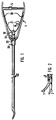
- the tissue forceps according to the invention have two jaw parts 1 and 2 for grasping and holding the tissue at the distal end, an actuating rod 3 connected to them and a handle 4 with an integrated locking mechanism or locking means 5 at the proximal end, which are used to fix the closed position of the jaw parts 1 and 2 cares.
- One jaw part 1 can be pivoted relative to the other 2 by axially adjusting the actuating rod 3 by means of the handle 4.
- the closing force that can be transmitted to the two jaw parts 1 and 2 with the actuating rod 3 can be adjustable, for example, in three defined stages.
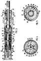
- Figure 3 shows such an embodiment with corresponding components. Here the device for switching the closing force is shown.
- Two compression springs 6 and 7 are provided, which transmit the force exerted on the actuating rod 3 via the handle 4 indirectly to the movable jaw part 1 when low closing forces are set. If the maximum closing force is to be transferred, see above this takes place immediately, ie not via intermediate compression springs, as will be explained later.
- the actuating rod 3 consists of a distal first rod part 8 and a second rod part 9 which extends proximally therefrom and a third rod part 10.
- the distal part 8 is connected directly to the swiveling jaw part 1, for example via a joint.
- the proximally extending second rod part 9 is designed so that it is rotatable relative to the first 8.
- the second rod part 9 is equipped with drivers 11, 12 and 13 which are arranged at an axial distance from one another and at an angle to one another and which cooperate with axially movable links 14, 15, 16, 17, 18, 19 and 20.
- the maximum closing force is to be transmitted, then in the rotational position of the second rod part 9 according to FIG. 3, only the driver 11 engages with the first link 14, 15 and 16 which is fixedly connected to the first rod part 8. If the closing force is reduced in stages, the driver 12 and then the driver 13 are in engagement with the respectively associated links 17, 18. Then the actuating force is transmitted to the first rod part 8 via the active backdrop and the compression spring 6.
- the link parts 14 to 20 are spring-biased in the proximal direction by the compression springs 6 and 7. It goes without saying that the number of components for the gradual closing force setting - such as compression springs, drivers and links - depends on the number of closing force stages provided. In the example shown here, three stages are provided.
- Figure 3 shows a position in which the maximum closing force is set. This is caused by the distal side Driver 11 is releasably fixed in the link 14, 15 and 16 and thus the force exerted on the proximally extending second and third rod parts 9, 10 is transmitted directly via the link parts 14, 15 to the first rod part 8, while the middle 12 and the proximal driver 13 can freely pass through the associated middle 17, 18 and proximal link 19, 20.
- FIG. 4 again illustrates the setting position described above.
- the distal driver 11 engages on the web 21 between the two oval recesses 22 located in the link parts 15 and 16, so that the force transmission upon axial displacement of the second and third rod parts 9, 10 onto the first rod part 8 can be done both in the distal and in the proximal direction.
- the recesses 22 serve for a free axial passage of the inactive drivers. In this case, it is drivers 12 and 13.
- the compression springs 6, 7 bring the link parts 18, 20 against ring shoulders 24 and 25 into contact, in such a way that the ring shoulders 24, 25 secure the link parts which are in the rest position against proximal movement.
- the annular shoulders 24, 25 are arranged in the device in such a way that they are permanently attached to a cylinder sleeve 27 arranged coaxially in the outer shaft 26. These are in turn fixed with their proximal end in the housing part 28, which is connected, for example, via a screw connection to the proximal housing part 29, on the proximal end of which handles 30 are fixed so as to be pivotable.
- brackets 31 for the movement transmission, which adjust the actuating rod 3 when the two handles 30 are pressed together so that the Handle 4 transmits the force starting from the handles 30 via the bracket 31 to the proximal rod part 10, so that the rod parts 8, 9 and 10 are finally axially displaced distally. Otherwise, the brackets 31 automatically return the handle 4 and the actuating rod 3 to the starting position after the locking device 5 has been released.
- a hollow cylindrical switching ring 32 is provided on the proximal rod part 10, by means of which a rotation of the rod part 9 is made possible.
- the switching ring 32 has an annular spring 34 which can be rotated relative to the fixed part 39. This engages with an inwardly directed nose 35 depending on the closing force to be set in one of the provided recesses 36, 37 or 38 of the fixed part 39.
- Figure 4 and Figure 5 show the interaction of the individual components. If the rod part 9 is rotated by means of the switching ring 32 via the cylinder sleeve 41 until the ring spring 34 is led out of the recess 36 with its nose 35 and engages in the recess 37 with further rotation, the middle driver 12 is located with the corresponding Baffles 17 and 18 in engagement, while both the distal 11 and the proximal driver 13 with the associated baffles 14, 15, 16 and 19, 20 are out of engagement. In this position, the closing force is determined by the compression spring 6. In this second setting, the closing force is lower.
- the transmission of the rotary movement of the switching ring 32 to the rotatable rod part 9, 10 takes place via the cylinder sleeve 41, which at its ends is non-detachably connected to the parts 9 and 32 and is connected to the cylinder sleeve 42.
- the cylinder sleeve 45 connected to the rod part 10 lies against the distal end of the cylinder sleeve 42.
- a bore 44 running centrally in the end face for receiving a pin 43 which is fixed centrally in the rod part 8 and with which the rod parts 8 and 9 are connected in an axially movable manner and due to the centering achieved thereby against radial movement is secured.
- 3 projections 11a, 12a and 13a are provided on the actuating rod, of which one each of each driver 11, 12 and 13 with approximately the thickness of the link Corresponding distance is assigned on the proximal side and, when the actuating rod is adjusted distally, comes into rotational engagement with the recess 22 assigned to it.
- the link parts 14, 17 and 19 should expediently be secured against radial rotation, for example by a pin engaging in an axially extending groove. Furthermore, the link parts 14, 15, 16 and 17, 18 and 19, 20 should be fixed inseparably to one another in order to ensure that the complementarily designed recesses 22 always assume the same position relative to one another, that is to say cannot be rotated relative to one another during operation. Otherwise there would not be the possibility that the projections that are not in engagement with a link can freely pass through the link parts that are out of engagement.
Landscapes
- Health & Medical Sciences (AREA)
- Engineering & Computer Science (AREA)
- Surgery (AREA)
- Mechanical Engineering (AREA)
- Life Sciences & Earth Sciences (AREA)
- Heart & Thoracic Surgery (AREA)
- Nuclear Medicine, Radiotherapy & Molecular Imaging (AREA)
- Biomedical Technology (AREA)
- Ophthalmology & Optometry (AREA)
- Medical Informatics (AREA)
- Molecular Biology (AREA)
- Animal Behavior & Ethology (AREA)
- General Health & Medical Sciences (AREA)
- Public Health (AREA)
- Veterinary Medicine (AREA)
- Surgical Instruments (AREA)
Applications Claiming Priority (2)
| Application Number | Priority Date | Filing Date | Title |
|---|---|---|---|
| DE4216971 | 1992-05-22 | ||
| DE4216971A DE4216971C2 (de) | 1992-05-22 | 1992-05-22 | Zange zum Fassen und Halten von Gewebe oder dergleichen |
Publications (2)
| Publication Number | Publication Date |
|---|---|
| EP0570675A1 true EP0570675A1 (fr) | 1993-11-24 |
| EP0570675B1 EP0570675B1 (fr) | 1995-10-18 |
Family
ID=6459504
Family Applications (1)
| Application Number | Title | Priority Date | Filing Date |
|---|---|---|---|
| EP93104077A Expired - Lifetime EP0570675B1 (fr) | 1992-05-22 | 1993-03-12 | Pince pour la préhension et le maintien de tissus |
Country Status (3)
| Country | Link |
|---|---|
| US (1) | US5354313A (fr) |
| EP (1) | EP0570675B1 (fr) |
| DE (2) | DE4216971C2 (fr) |
Cited By (3)
| Publication number | Priority date | Publication date | Assignee | Title |
|---|---|---|---|---|
| US9962222B2 (en) | 2010-10-01 | 2018-05-08 | Applied Medical Resources Corporation | Electrosurgical instruments and connections thereto |
| US10342604B2 (en) | 2008-03-31 | 2019-07-09 | Applied Medical Resources Corporation | Electrosurgical system |
| US10420603B2 (en) | 2014-12-23 | 2019-09-24 | Applied Medical Resources Corporation | Bipolar electrosurgical sealer and divider |
Families Citing this family (31)
| Publication number | Priority date | Publication date | Assignee | Title |
|---|---|---|---|---|
| DE4303274C2 (de) * | 1993-02-05 | 1997-02-06 | Wolf Gmbh Richard | Endoskopisches Instrument |
| DE4408475A1 (de) * | 1994-03-14 | 1995-09-21 | Wolf Gmbh Richard | Chirurgische Zange |
| US5803649A (en) * | 1995-11-14 | 1998-09-08 | Hoogeboom; Thomas J. | Locking mechanism |
| DE19707374C2 (de) * | 1997-02-25 | 2000-10-26 | Storz Karl Gmbh & Co Kg | Medizinischer Dissektionsspatel mit spreizbaren Spatelmaulteilen |
| US6280458B1 (en) | 1997-07-22 | 2001-08-28 | Karl Storz Gmbh & Co. Kg | Surgical grasping and holding forceps |
| DE19731454A1 (de) | 1997-07-22 | 1999-03-04 | Storz Karl Gmbh & Co | Chirurgische Faß- und Haltezange |
| DE19857323A1 (de) * | 1998-12-11 | 2000-06-21 | Aesculap Ag & Co Kg | Chirurgisches Instrument |
| USD583472S1 (en) * | 2006-09-21 | 2008-12-23 | Karl Storz Gmbh & Co. Kg | Needle holder |
| AU2007221906B1 (en) * | 2007-10-09 | 2008-10-23 | John Silady | Control System for A Grasping Instrument |
| USD610682S1 (en) * | 2008-06-20 | 2010-02-23 | Karl Storz Gmbh & Co., Kg | Shaft for medical forceps |
| USD617897S1 (en) * | 2008-06-23 | 2010-06-15 | Karl Storz Gmbh & Co. Kg | Handle for medical instrument |
| FR2948594B1 (fr) * | 2009-07-31 | 2012-07-20 | Dexterite Surgical | Manipulateur ergonomique et semi-automatique et applications aux instruments pour chirurgie mini-invasive |
| WO2011044560A2 (fr) | 2009-10-09 | 2011-04-14 | Applied Medical Resources Corporation | Instruments à trocart unique |
| USD639944S1 (en) * | 2009-12-22 | 2011-06-14 | Karl Storz Gmbh & Co. Kg | Needle holder |
| US20110190794A1 (en) * | 2010-01-29 | 2011-08-04 | Richard Wolf Gmbh | Medical needle holder |
| USD652924S1 (en) * | 2010-05-11 | 2012-01-24 | Karl Storz Gmbh & Co. Kg | Forceps |
| USD649247S1 (en) * | 2010-05-11 | 2011-11-22 | Karl Storz Gmbh & Co. Kg | Forceps |
| GB2509110B (en) * | 2012-12-20 | 2018-07-18 | Gerard Michael Brooke | Electrosurgical Forceps with Adjustable Spring |
| JP6573663B2 (ja) | 2014-05-16 | 2019-09-11 | アプライド メディカル リソーシーズ コーポレイション | 電気外科的システム |
| AU2015266619B2 (en) | 2014-05-30 | 2020-02-06 | Applied Medical Resources Corporation | Electrosurgical instrument for fusing and cutting tissue and an electrosurgical generator |
| WO2016065225A1 (fr) | 2014-10-24 | 2016-04-28 | GYRUS ACMI, INC. (d/b/a OLYMPUS SURGICAL TECHNOLOGIES AMERICA) | Instrument comprenant une pince à mâchoires résilientes |
| USD775332S1 (en) | 2014-12-18 | 2016-12-27 | Karl Storz Gmbh & Co. Kg | Needle holder |
| USD748259S1 (en) | 2014-12-29 | 2016-01-26 | Applied Medical Resources Corporation | Electrosurgical instrument |
| US10349963B2 (en) | 2016-06-14 | 2019-07-16 | Gyrus Acmi, Inc. | Surgical apparatus with jaw force limiter |
| US11179190B2 (en) | 2017-12-12 | 2021-11-23 | Gyrus Acmi, Inc. | Laparoscopic forceps assembly with an operable mechanism |
| EP4480434B1 (fr) | 2018-09-05 | 2026-06-24 | Applied Medical Resources Corporation | Système de commande de générateur électrochirurgical |
| KR102862074B1 (ko) | 2018-11-16 | 2025-09-22 | 어플라이드 메디컬 리소시스 코포레이션 | 전기수술용 시스템 |
| CN109331903B (zh) * | 2018-11-23 | 2020-12-18 | 灵璧县浩翔信息科技有限公司 | 一种五金简单铸造用坩埚夹 |
| US11350957B2 (en) | 2019-03-27 | 2022-06-07 | Gyms Acmi, Inc. | Laparoscopic forceps assembly for gripping and dissection |
| US11529159B2 (en) | 2019-03-29 | 2022-12-20 | Gyrus Acmi, Inc. | Forceps jaw flanges |
| KR102693046B1 (ko) * | 2022-06-02 | 2024-08-08 | 선지호 | 방향전환 기능이 있는 집게 |
Citations (3)
| Publication number | Priority date | Publication date | Assignee | Title |
|---|---|---|---|---|
| GB2208201A (en) * | 1987-07-13 | 1989-03-15 | Serge Reiss | Surgical instrument |
| US4944739A (en) * | 1989-03-24 | 1990-07-31 | Torre Randall J | Bone gripping fixation clamp |
| US5009661A (en) * | 1989-04-24 | 1991-04-23 | Michelson Gary K | Protective mechanism for surgical rongeurs |
Family Cites Families (8)
| Publication number | Priority date | Publication date | Assignee | Title |
|---|---|---|---|---|
| US1350675A (en) * | 1919-11-28 | 1920-08-24 | James H Smith | Lifting-tongs |
| US4602631A (en) * | 1983-09-08 | 1986-07-29 | Noboru Funatsu | Forceps for clamping surgical clips |
| DE3601166A1 (de) * | 1986-01-17 | 1987-07-23 | Hermann Dausch | Mikrochirurgische zange, insb. fuer die arthroskopische chirurgie |
| DE8813678U1 (de) * | 1988-11-02 | 1989-01-05 | Lorenz, Hans, 2940 Wilhelmshaven | Geschlossene Greifzange mit veränderlichem Anpressdruck |
| US4968078A (en) * | 1989-05-24 | 1990-11-06 | Edwin Fitzwater | Adjustable compound-action clamp |
| DE3931577A1 (de) * | 1989-09-22 | 1991-04-04 | Wolf Gmbh Richard | Halteelement fuer handgriffarme medizinischer instrumente |
| DE4010775A1 (de) * | 1990-04-04 | 1991-10-17 | Wolf Gmbh Richard | Medizinische zange |
| US5222973A (en) * | 1992-03-09 | 1993-06-29 | Sharpe Endosurgical Corporation | Endoscopic grasping tool surgical instrument |
-
1992
- 1992-05-22 DE DE4216971A patent/DE4216971C2/de not_active Expired - Fee Related
-
1993
- 1993-03-12 DE DE59300771T patent/DE59300771D1/de not_active Expired - Fee Related
- 1993-03-12 EP EP93104077A patent/EP0570675B1/fr not_active Expired - Lifetime
- 1993-05-21 US US08/065,628 patent/US5354313A/en not_active Expired - Fee Related
Patent Citations (3)
| Publication number | Priority date | Publication date | Assignee | Title |
|---|---|---|---|---|
| GB2208201A (en) * | 1987-07-13 | 1989-03-15 | Serge Reiss | Surgical instrument |
| US4944739A (en) * | 1989-03-24 | 1990-07-31 | Torre Randall J | Bone gripping fixation clamp |
| US5009661A (en) * | 1989-04-24 | 1991-04-23 | Michelson Gary K | Protective mechanism for surgical rongeurs |
Non-Patent Citations (1)
| Title |
|---|
| DATABASE WPI Week 8931, Derwent Publications Ltd., London, GB; AN 89-225985 & SU-A-1 437 207 (YURKOV) * |
Cited By (8)
| Publication number | Priority date | Publication date | Assignee | Title |
|---|---|---|---|---|
| US10342604B2 (en) | 2008-03-31 | 2019-07-09 | Applied Medical Resources Corporation | Electrosurgical system |
| US10888371B2 (en) | 2008-03-31 | 2021-01-12 | Applied Medical Resources Corporation | Electrosurgical system |
| US11660136B2 (en) | 2008-03-31 | 2023-05-30 | Applied Medical Resources Corporation | Electrosurgical system |
| US12295642B2 (en) | 2008-03-31 | 2025-05-13 | Applied Medical Resources Corporation | Electrosurgical system |
| US9962222B2 (en) | 2010-10-01 | 2018-05-08 | Applied Medical Resources Corporation | Electrosurgical instruments and connections thereto |
| US10874452B2 (en) | 2010-10-01 | 2020-12-29 | Applied Medical Resources Corporation | Electrosurgical instruments and connections thereto |
| US12357374B2 (en) | 2010-10-01 | 2025-07-15 | Applied Medical Resources Corporation | Electrosurgical instruments and connections thereto |
| US10420603B2 (en) | 2014-12-23 | 2019-09-24 | Applied Medical Resources Corporation | Bipolar electrosurgical sealer and divider |
Also Published As
| Publication number | Publication date |
|---|---|
| DE4216971C2 (de) | 1995-06-08 |
| DE59300771D1 (de) | 1995-11-23 |
| US5354313A (en) | 1994-10-11 |
| EP0570675B1 (fr) | 1995-10-18 |
| DE4216971A1 (de) | 1993-11-25 |
Similar Documents
| Publication | Publication Date | Title |
|---|---|---|
| EP0570675B1 (fr) | Pince pour la préhension et le maintien de tissus | |
| DE10102089C1 (de) | Chirurgisches Instrument | |
| DE69903094T2 (de) | Klemmvorrichtung | |
| EP0613660B1 (fr) | Pince chirurgicale | |
| EP1323499B1 (fr) | Pince étau ou pince extensible | |
| DE69313683T2 (de) | Repositions-Instrument für Pedikelschrauben | |
| DE19852682C2 (de) | Chirurgisches Schienenschaftinstrument | |
| EP0860148A2 (fr) | Attache de type à baionnette pour l'assemblage démontable de deux instruments tubulaires ou de deux pièces d'un instrument | |
| DE29623113U1 (de) | Axialgriff für chirurgische, insbesondere endoskopische Instrumente | |
| DE3711377A1 (de) | Chirurgisches instrument | |
| DE2354639A1 (de) | Steckschluessel-knarre bzw. -ratsche | |
| DE102014102606A1 (de) | Mikrochirurgisches Halte- und/oder Schneidinstrument | |
| DE19636594A1 (de) | Löseeinheit | |
| EP4054447B1 (fr) | Instrument médical à tige coulissante | |
| DE102013107308A1 (de) | Stabeinsetzinstrument | |
| DE9307793U1 (de) | Chirurgisches Rohrschaftinstrument | |
| EP3563973B1 (fr) | Pince | |
| DE69607645T2 (de) | Mehrzweckzange | |
| DE19712645C1 (de) | Kupplung zum Kuppeln zweier optischer Einrichtungen | |
| EP2085186A2 (fr) | Pince étau ou pince extensible | |
| DE102021119531B4 (de) | Chirurgisches Instrument und Verriegelungsvorrichtung dafür | |
| DE102013105240A1 (de) | Stabhaltezange mit Winkelverstellung | |
| DE9114306U1 (de) | Chirurgisches Rohrschaftinstrument | |
| DE19640896A1 (de) | Medizinisches Instrument | |
| EP4192366B1 (fr) | Instrument chirurgical |
Legal Events
| Date | Code | Title | Description |
|---|---|---|---|
| PUAI | Public reference made under article 153(3) epc to a published international application that has entered the european phase |
Free format text: ORIGINAL CODE: 0009012 |
|
| AK | Designated contracting states |
Kind code of ref document: A1 Designated state(s): BE CH DE FR GB LI |
|
| 17P | Request for examination filed |
Effective date: 19931224 |
|
| 17Q | First examination report despatched |
Effective date: 19950321 |
|
| GRAA | (expected) grant |
Free format text: ORIGINAL CODE: 0009210 |
|
| AK | Designated contracting states |
Kind code of ref document: B1 Designated state(s): BE CH DE FR GB LI |
|
| REF | Corresponds to: |
Ref document number: 59300771 Country of ref document: DE Date of ref document: 19951123 |
|
| GBT | Gb: translation of ep patent filed (gb section 77(6)(a)/1977) |
Effective date: 19951216 |
|
| REG | Reference to a national code |
Ref country code: CH Ref legal event code: NV Representative=s name: ISLER & PEDRAZZINI AG PATENTANWAELTE |
|
| ET | Fr: translation filed | ||
| PGFP | Annual fee paid to national office [announced via postgrant information from national office to epo] |
Ref country code: BE Payment date: 19960308 Year of fee payment: 4 |
|
| PGFP | Annual fee paid to national office [announced via postgrant information from national office to epo] |
Ref country code: FR Payment date: 19960311 Year of fee payment: 4 |
|
| PG25 | Lapsed in a contracting state [announced via postgrant information from national office to epo] |
Ref country code: LI Effective date: 19960331 Ref country code: CH Effective date: 19960331 |
|
| PLBE | No opposition filed within time limit |
Free format text: ORIGINAL CODE: 0009261 |
|
| 26N | No opposition filed | ||
| REG | Reference to a national code |
Ref country code: CH Ref legal event code: PL |
|
| PG25 | Lapsed in a contracting state [announced via postgrant information from national office to epo] |
Ref country code: DE Effective date: 19961203 |
|
| PG25 | Lapsed in a contracting state [announced via postgrant information from national office to epo] |
Ref country code: GB Effective date: 19970312 |
|
| PG25 | Lapsed in a contracting state [announced via postgrant information from national office to epo] |
Ref country code: BE Effective date: 19970331 |
|
| BERE | Be: lapsed |
Owner name: RICHARD WOLF G.M.B.H. Effective date: 19970331 |
|
| GBPC | Gb: european patent ceased through non-payment of renewal fee |
Effective date: 19970312 |
|
| PG25 | Lapsed in a contracting state [announced via postgrant information from national office to epo] |
Ref country code: FR Free format text: LAPSE BECAUSE OF NON-PAYMENT OF DUE FEES Effective date: 19971128 |
|
| REG | Reference to a national code |
Ref country code: FR Ref legal event code: ST |