EP0570710A1 - Elektrodenanordnung - Google Patents
Elektrodenanordnung Download PDFInfo
- Publication number
- EP0570710A1 EP0570710A1 EP93106505A EP93106505A EP0570710A1 EP 0570710 A1 EP0570710 A1 EP 0570710A1 EP 93106505 A EP93106505 A EP 93106505A EP 93106505 A EP93106505 A EP 93106505A EP 0570710 A1 EP0570710 A1 EP 0570710A1
- Authority
- EP
- European Patent Office
- Prior art keywords
- electrode
- conductors
- conductor
- coiled
- contact
- Prior art date
- Legal status (The legal status is an assumption and is not a legal conclusion. Google has not performed a legal analysis and makes no representation as to the accuracy of the status listed.)
- Ceased
Links
Images

Classifications
-
- A—HUMAN NECESSITIES
- A61—MEDICAL OR VETERINARY SCIENCE; HYGIENE
- A61N—ELECTROTHERAPY; MAGNETOTHERAPY; RADIATION THERAPY; ULTRASOUND THERAPY
- A61N1/00—Electrotherapy; Circuits therefor
- A61N1/02—Details
- A61N1/04—Electrodes
- A61N1/05—Electrodes for implantation or insertion into the body, e.g. heart electrode
- A61N1/056—Transvascular endocardial electrode systems
- A61N1/0565—Electrode heads
-
- A—HUMAN NECESSITIES
- A61—MEDICAL OR VETERINARY SCIENCE; HYGIENE
- A61N—ELECTROTHERAPY; MAGNETOTHERAPY; RADIATION THERAPY; ULTRASOUND THERAPY
- A61N1/00—Electrotherapy; Circuits therefor
- A61N1/02—Details
- A61N1/04—Electrodes
- A61N1/05—Electrodes for implantation or insertion into the body, e.g. heart electrode
- A61N1/056—Transvascular endocardial electrode systems
Definitions
- the invention relates to an electrode device for a medical apparatus for stimulating living tissue with electrical impulses, comprising at least two coiled conductors which are electrically and mechanically interconnected in a contact area.
- a defibrillation electrode comprising an electrode catheter in which a first coiled electrode conductor runs and an electrode carrier on which a second coiled electrode conductor is arranged in a specific pattern.
- One end of each electrode conductor is inserted into a coupling sleeve which is crimped onto the respective end to electrically and mechanically interconnect the two electrode conductors.
- the defibrillator electrode is designed for implantation in the heart of a patient.
- the prior art electrode device has a plurality of electrode conductors arranged in simple, closed loops on the electrode carrier. All the conductors are mechanically and electrically coupled in the coupling sleeve.
- Coupling conductors with a coupling sleeve have certain disadvantages.
- crimping of the coupling sleeve must be firm enough to prevent detachment of any conductor, thereby breaking the electrical connection. But crimping must not be too forceful, since it might then damage the conductors.
- When a plurality of conductors is to be interconnected there is a risk of one of the connections being defective. Since the prior art electrode device is to stimulate the heart, it is exposed to constant, dynamic loading. The contact area is therefore subjected to a large number of load changes which could cause conductor fatigue in the attachment area, since the coupling sleeve is completely inflexible but the conductors are flexible.
- the conductors are also connected in a contact sleeve which restricts the design of the specific pattern in which the conductors are arranged. If more than one contact sleeve were used when a plurality of conductors is arranged on the electrode carrier, the entire defibrillation electrode would be stiff and obstruct the heart's movements. Moreover, coupling cannot be disengaged, and the number of parts required for assembly of the electrode device increases.
- the object of the invention is to produce an electrode, as described above, in which interconnection of the conductors is mechanically and electrically reliable, elastic and resilient, fewer assembly items are required and the conductors are not damaged, either in assembly or after long-term use.
- the electrode device as described above, is devised so the conductors in the contact area are coiled around each other or intertwined with each other, whereby the spring force forms the elctrical and mechanical interconnection.
- the electrode device comprises a defibrillation electrode with an electrode carrier, on which at least one of the coiled conductors is arranged in a predetermined pattern to form an electrode surface through which electrical pulses are transmitted to the living tissue, and an electrode catheter in which the other coiled conductor is provided.
- Such an electrode device can be applied directly to the heart or subcutaneously at a given distance from the heart.
- the contact area is flexible and resilient.
- the conductors can be interconnected anywhere on the electrode carrier without the defibrillation electrode losing any flexibility. This is particularly important in cases in which the electrode is applied directly to the heart.
- the electrode conductors in this invention can be arranged so distribution of current in the electrode surface is optimized and the effects of a broken conductor in the defibrillation electrode are minimized.
- the electrode device contains at least one symmetrical lead, one of the coiled conductors is provided inside the lead, and a second coiled conductor is provided inside the electrode catheter.
- Discharge of the electrical lead's pulses is desirable in e.g. electrode devices for defibrillating a heart when an electrical pulse must be emitted simultaneously across cardiac tissue from one electrode surface to two other electrode surfaces located at a distance from one another and which are electrically connected to one another via the lead. It is then important for the electrode conductor to retain its flexibility even at the branching point, something which is made possible, according to the invention, by intertwining of the coiled conductors. Only one connection contact with the defibrillator is needed for the two electrode surfaces.
- the electrode so it comprises a detachable adapter device, with anelectrode catheter with a connection contact at one end and a first contact fixture at its other end, and a symmetrical lead with a second contact fixture at its free end, one of the coiled conductors provided inside the lead and one of the other coiled conductors provided inside the electrode catheter.
- Construction of the contact fixture makes possible a plurality of versions of the electrode device with only a small number of parts.
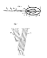
- FIG. 1 illustrates an electrode device 1 comprising an electrode catheter 2 and an electrode 3 which are connected to one another in a contact area 4.
- the electrode catheter 2 has a connection contact 5 for coupling the electrode device 1 to a stimulation pulse generator (not shown) such as a defibrillator.
- a first coiled electrode conductor 6 runs inside the electrode catheter 2.
- the first electrode conductor 6 runs through the entire contact area 4 and, as an extension of the electrode catheter 2, out onto an electrode carrier 7 to the defibrillation electrode 3 up to the distal end of the defibrillationelectrode 3.
- In the contact area 4 there is a second spiral electrode
- the second electrode conductor 8 which is connected to the first electrode conductor 6.
- the second electrode conductor 8 runs in an arc along the periphery of the electrode carrier 7 in a closed loop back to the contact area 4.
- a third spiral electrode conductors 9 runs across the electrode carrier 7 and is connected to the second electrode conductor 8 in two opposite contact areas 23, 24 on the electrode carrier 7.
- FIG. 2 illustrates how the first electrode conductor 6 is connected to the second electrode conductor 8 by enclosure of a stretch of the first electrode conductor 6 by the second electrode conductor 8.
- the spring force in the secondelec- trode conductor 8 achieves sufficient mechanical and electricalcoupling.
- the second electrode conductor 8 and the third electrode conductor 9 are interconnected in the corresponding matter in the contact areas 23, 24.
- FIG. 3 illustrates an adapter device 12 which can constitute a detachable part of an electrode device.
- the adapter device 12 comprises a connection contact 13 at its proximal end, intended for connection to a stimulation pulse generator (not shown) such as a defibrillator, an electrode catheter 17 with a symmetrical lead 18 which divides the electrode catheter 17 into two branches 18, 19, a first contact fixture 14 and a second contact fixture 15 at the distal end of the respective branch 18, 19.
- a first coiled electrode conductor 16 connects the connection contact 13 to the first contact fixture 14.
- a second coiled electrode conductor 21 is provided inside the lead 18, and the second electrode conductor 21 is connected to the first electrode conductor 16 in a contact area 20.
- the second electrode conductor 21 is connected to the second contact fixture 15, thereby connecting the second contact fixture 15 to the connection contact 13 and to the first contact fixture 14. Construction of the connection itself is described in greater detail in conjunction with FIG. 4 below.
- the electrode device 1 in FIG. 1 can beconnec- ted to the contact fixture 14, and a second electrode device, with a transvenous electrode catheter, can be connected to the second contact fixture 15.
- a second electrode device with a transvenous electrode catheter
- a defibrillator pulse generated by the defibrillator and emitted from a third electrode device across the heart, returns to the defibrillator via the electrode device 1 and the second electrode device.
- the number of couplings to the defibrillator for returning stimulation pulses is thereby minimized to just one. If the second electrode device and the third electrode device are devised as a single electrode device with two defibrillation electrode arranged along the same transvenous electrode catheter and electrically separated from one another, as illustrated by said document (US-A-4,662,377), the total number of connections to the defibrillator can be reduced to just one.
- the adapter device 12 contains a third conductor 22 which is electrically separated from the other conductors 16, 21 and which runs from the connection contact 13 to the second contact fixture 15 to electrically couple the defibrillator to the third defibrillator electrode.
- FIG. 4 shows that the third conductor 22 is coiled into a smaller diameter than the first conductor 16 and provided inside the electrode catheter 17 in such a way that it runs in the channel formed by the coiled first conductor 16.
- the electrode device can also be devised in the abovedescribed way without a detachable adapter part.
- FIG. 4 shows a construction for a coupling of the two electrode conductors 16, 21.
- the two electrode conductors 16 and 21 are intertwined over a given distance.
- spring force helps to make the coupling mechanically safe and stable while simultaneously assuring a good electrical coupling.
Landscapes
- Health & Medical Sciences (AREA)
- Heart & Thoracic Surgery (AREA)
- Vascular Medicine (AREA)
- Cardiology (AREA)
- Engineering & Computer Science (AREA)
- Biomedical Technology (AREA)
- Nuclear Medicine, Radiotherapy & Molecular Imaging (AREA)
- Radiology & Medical Imaging (AREA)
- Life Sciences & Earth Sciences (AREA)
- Animal Behavior & Ethology (AREA)
- General Health & Medical Sciences (AREA)
- Public Health (AREA)
- Veterinary Medicine (AREA)
- Electrotherapy Devices (AREA)
- Printers Or Recording Devices Using Electromagnetic And Radiation Means (AREA)
- Measurement And Recording Of Electrical Phenomena And Electrical Characteristics Of The Living Body (AREA)
Applications Claiming Priority (2)
| Application Number | Priority Date | Filing Date | Title |
|---|---|---|---|
| SE9201601A SE9201601L (sv) | 1992-05-21 | 1992-05-21 | Elektrodanordning |
| SE9201601 | 1992-05-21 |
Publications (1)
| Publication Number | Publication Date |
|---|---|
| EP0570710A1 true EP0570710A1 (de) | 1993-11-24 |
Family
ID=20386304
Family Applications (1)
| Application Number | Title | Priority Date | Filing Date |
|---|---|---|---|
| EP93106505A Ceased EP0570710A1 (de) | 1992-05-21 | 1993-04-21 | Elektrodenanordnung |
Country Status (4)
| Country | Link |
|---|---|
| US (1) | US5405372A (de) |
| EP (1) | EP0570710A1 (de) |
| JP (1) | JPH0631002A (de) |
| SE (1) | SE9201601L (de) |
Cited By (3)
| Publication number | Priority date | Publication date | Assignee | Title |
|---|---|---|---|---|
| WO2000027471A1 (en) * | 1998-11-10 | 2000-05-18 | Intermedics Inc. | Cardiac lead with etfe coated dbs coil |
| US6141593A (en) * | 1998-11-10 | 2000-10-31 | Intermedics Inc. | Cardiac lead with ETEE coated DBS coil |
| US7239923B1 (en) | 2000-08-01 | 2007-07-03 | Cardiac Pacemakers, Inc. | Lead having varying stiffness and method of manufacturing thereof |
Families Citing this family (5)
| Publication number | Priority date | Publication date | Assignee | Title |
|---|---|---|---|---|
| ITRM940130A1 (it) * | 1994-03-10 | 1995-09-11 | P A & M Spa | Elemento di sicurezza atto a garantire nel tempo l'affidabilita' elettrica degli elettrodocateteri per la stimolazione elettrica del |
| US6253111B1 (en) | 1998-03-30 | 2001-06-26 | Pacesetter, Inc. | Multi-conductor lead |
| RU2348432C2 (ru) * | 2004-03-26 | 2009-03-10 | Аслам ХАН | Аппарат для импульсной терапии спинного и верхнешейного отдела позвоночника |
| US8019442B1 (en) * | 2006-10-25 | 2011-09-13 | Advanced Neuromodulation Systems, Inc. | Assembly kit for creating paddle-style lead from one or several percutaneous leads and method of lead implantation |
| US8380325B2 (en) | 2009-08-05 | 2013-02-19 | Boston Scientific Neuromodulation Corporation | Systems and methods for coupling coiled conductors to conductive contacts of an electrical stimulation system |
Citations (4)
| Publication number | Priority date | Publication date | Assignee | Title |
|---|---|---|---|---|
| US4026303A (en) * | 1975-11-17 | 1977-05-31 | Vitatron Medical B.V. | Endocardial pacing electrode |
| US4393883A (en) * | 1980-11-03 | 1983-07-19 | Medtronic, Inc. | Single pass A-V lead |
| US4953564A (en) * | 1989-08-23 | 1990-09-04 | Medtronic, Inc. | Screw-in drug eluting lead |
| US5105826A (en) * | 1990-10-26 | 1992-04-21 | Medtronic, Inc. | Implantable defibrillation electrode and method of manufacture |
Family Cites Families (5)
| Publication number | Priority date | Publication date | Assignee | Title |
|---|---|---|---|---|
| FR1332217A (fr) * | 1961-07-01 | 1963-07-12 | Bayerische Schrauben Und Feder | Dispositif d'attache d'un câble conducteur électrique au moyen de fils vrillés enhélice |
| US4360031A (en) * | 1980-09-11 | 1982-11-23 | Medtronic, Inc. | Drug dispensing irrigatable electrode |
| US4508419A (en) * | 1982-09-30 | 1985-04-02 | Anibal Galindo | Hypodermic needle connector |
| DE3718324A1 (de) * | 1987-06-01 | 1988-12-22 | Siemens Ag | Herzschrittmacherelektrode |
| US5122136A (en) * | 1990-03-13 | 1992-06-16 | The Regents Of The University Of California | Endovascular electrolytically detachable guidewire tip for the electroformation of thrombus in arteries, veins, aneurysms, vascular malformations and arteriovenous fistulas |
-
1992
- 1992-05-21 SE SE9201601A patent/SE9201601L/ not_active Application Discontinuation
-
1993
- 1993-04-21 EP EP93106505A patent/EP0570710A1/de not_active Ceased
- 1993-05-19 US US08/063,568 patent/US5405372A/en not_active Expired - Lifetime
- 1993-05-21 JP JP5119473A patent/JPH0631002A/ja active Pending
Patent Citations (4)
| Publication number | Priority date | Publication date | Assignee | Title |
|---|---|---|---|---|
| US4026303A (en) * | 1975-11-17 | 1977-05-31 | Vitatron Medical B.V. | Endocardial pacing electrode |
| US4393883A (en) * | 1980-11-03 | 1983-07-19 | Medtronic, Inc. | Single pass A-V lead |
| US4953564A (en) * | 1989-08-23 | 1990-09-04 | Medtronic, Inc. | Screw-in drug eluting lead |
| US5105826A (en) * | 1990-10-26 | 1992-04-21 | Medtronic, Inc. | Implantable defibrillation electrode and method of manufacture |
Cited By (4)
| Publication number | Priority date | Publication date | Assignee | Title |
|---|---|---|---|---|
| WO2000027471A1 (en) * | 1998-11-10 | 2000-05-18 | Intermedics Inc. | Cardiac lead with etfe coated dbs coil |
| WO2000027470A1 (en) * | 1998-11-10 | 2000-05-18 | Intermedics Inc. | Cardiac lead with reduced inner crimp sleeve |
| US6141593A (en) * | 1998-11-10 | 2000-10-31 | Intermedics Inc. | Cardiac lead with ETEE coated DBS coil |
| US7239923B1 (en) | 2000-08-01 | 2007-07-03 | Cardiac Pacemakers, Inc. | Lead having varying stiffness and method of manufacturing thereof |
Also Published As
| Publication number | Publication date |
|---|---|
| JPH0631002A (ja) | 1994-02-08 |
| US5405372A (en) | 1995-04-11 |
| SE9201601D0 (sv) | 1992-05-21 |
| SE9201601L (sv) | 1993-11-22 |
Similar Documents
| Publication | Publication Date | Title |
|---|---|---|
| US3788329A (en) | Body implantable lead | |
| US4236525A (en) | Multiple function lead assembly | |
| US6096069A (en) | Medical electrical lead with conductors coiled around an inner tube | |
| US5086773A (en) | Tool-less pacemaker lead assembly | |
| US4411276A (en) | Implantable multiple connector | |
| US7242987B2 (en) | Medical lead adaptor | |
| EP0689469B1 (de) | Hochfrequenzleiterbefestigung | |
| EP1370322B1 (de) | Leitung mit zwischen elektroden einstellbaren winkel- und raumpositionen | |
| US6066165A (en) | Medical lead with sigma feature | |
| US5397342A (en) | Resilient structurally coupled and electrically independent electrodes | |
| US6350160B1 (en) | Medical connector system and method of use | |
| US4030508A (en) | Low output electrode for cardiac pacing | |
| US7195523B2 (en) | Electrical conductive path for a medical electronics device | |
| US6671553B1 (en) | Implantable cardiac lead having terminating connector strain relief and method of manufacture | |
| USRE31990E (en) | Multiple function lead assembly and method for inserting assembly into an implantable tissue stimulator | |
| EP0627235B1 (de) | Medizinisches System | |
| US5899933A (en) | Nerve cuff electrode carrier | |
| JP3614368B2 (ja) | 心臓用リード線を心拍管理装置に接続するための器具 | |
| US5387234A (en) | Medical electrode device | |
| CA2398962A1 (en) | Medical implant device for electrostimulation using discrete micro-electrodes | |
| WO1992009329A1 (en) | Method and apparatus for cardiac defibrillation | |
| US20030120327A1 (en) | Medical lead adaptor assembly with retainer | |
| US5662696A (en) | One piece disposable threshold test can electrode for use with an implantable cardioverter defibrillator system | |
| WO2004101063A1 (en) | Medical lead adaptor assembly | |
| WO1998030281A1 (en) | Filtered feedthrough for an implantable medical device |
Legal Events
| Date | Code | Title | Description |
|---|---|---|---|
| PUAI | Public reference made under article 153(3) epc to a published international application that has entered the european phase |
Free format text: ORIGINAL CODE: 0009012 |
|
| AK | Designated contracting states |
Kind code of ref document: A1 Designated state(s): DE FR GB IT NL SE |
|
| RIN1 | Information on inventor provided before grant (corrected) |
Inventor name: HIRSCHBERG, JAKUB Inventor name: NEUBAUER, HEINZ Inventor name: GILLJAM, NINA |
|
| 17P | Request for examination filed |
Effective date: 19940407 |
|
| RAP1 | Party data changed (applicant data changed or rights of an application transferred) |
Owner name: PACESETTER AB |
|
| 17Q | First examination report despatched |
Effective date: 19951005 |
|
| GRAG | Despatch of communication of intention to grant |
Free format text: ORIGINAL CODE: EPIDOS AGRA |
|
| 18R | Application refused |
Effective date: 19971205 |