EP0571136A2 - Entwicklungsvorrichtung mit einer Toner-Zuführeinheit - Google Patents
Entwicklungsvorrichtung mit einer Toner-Zuführeinheit Download PDFInfo
- Publication number
- EP0571136A2 EP0571136A2 EP93303724A EP93303724A EP0571136A2 EP 0571136 A2 EP0571136 A2 EP 0571136A2 EP 93303724 A EP93303724 A EP 93303724A EP 93303724 A EP93303724 A EP 93303724A EP 0571136 A2 EP0571136 A2 EP 0571136A2
- Authority
- EP
- European Patent Office
- Prior art keywords
- developing
- toner supply
- toner
- supply unit
- unit
- Prior art date
- Legal status (The legal status is an assumption and is not a legal conclusion. Google has not performed a legal analysis and makes no representation as to the accuracy of the status listed.)
- Withdrawn
Links
Images


Classifications
-
- G—PHYSICS
- G03—PHOTOGRAPHY; CINEMATOGRAPHY; ANALOGOUS TECHNIQUES USING WAVES OTHER THAN OPTICAL WAVES; ELECTROGRAPHY; HOLOGRAPHY
- G03G—ELECTROGRAPHY; ELECTROPHOTOGRAPHY; MAGNETOGRAPHY
- G03G15/00—Apparatus for electrographic processes using a charge pattern
- G03G15/06—Apparatus for electrographic processes using a charge pattern for developing
- G03G15/08—Apparatus for electrographic processes using a charge pattern for developing using a solid developer, e.g. powder developer
- G03G15/0896—Arrangements or disposition of the complete developer unit or parts thereof not provided for by groups G03G15/08 - G03G15/0894
-
- G—PHYSICS
- G03—PHOTOGRAPHY; CINEMATOGRAPHY; ANALOGOUS TECHNIQUES USING WAVES OTHER THAN OPTICAL WAVES; ELECTROGRAPHY; HOLOGRAPHY
- G03G—ELECTROGRAPHY; ELECTROPHOTOGRAPHY; MAGNETOGRAPHY
- G03G15/00—Apparatus for electrographic processes using a charge pattern
- G03G15/06—Apparatus for electrographic processes using a charge pattern for developing
- G03G15/08—Apparatus for electrographic processes using a charge pattern for developing using a solid developer, e.g. powder developer
- G03G15/0822—Arrangements for preparing, mixing, supplying or dispensing developer
- G03G15/0877—Arrangements for metering and dispensing developer from a developer cartridge into the development unit
-
- G—PHYSICS
- G03—PHOTOGRAPHY; CINEMATOGRAPHY; ANALOGOUS TECHNIQUES USING WAVES OTHER THAN OPTICAL WAVES; ELECTROGRAPHY; HOLOGRAPHY
- G03G—ELECTROGRAPHY; ELECTROPHOTOGRAPHY; MAGNETOGRAPHY
- G03G15/00—Apparatus for electrographic processes using a charge pattern
- G03G15/06—Apparatus for electrographic processes using a charge pattern for developing
- G03G15/08—Apparatus for electrographic processes using a charge pattern for developing using a solid developer, e.g. powder developer
- G03G15/0822—Arrangements for preparing, mixing, supplying or dispensing developer
- G03G15/0887—Arrangements for conveying and conditioning developer in the developing unit, e.g. agitating, removing impurities or humidity
- G03G15/0891—Arrangements for conveying and conditioning developer in the developing unit, e.g. agitating, removing impurities or humidity for conveying or circulating developer, e.g. augers
-
- Y—GENERAL TAGGING OF NEW TECHNOLOGICAL DEVELOPMENTS; GENERAL TAGGING OF CROSS-SECTIONAL TECHNOLOGIES SPANNING OVER SEVERAL SECTIONS OF THE IPC; TECHNICAL SUBJECTS COVERED BY FORMER USPC CROSS-REFERENCE ART COLLECTIONS [XRACs] AND DIGESTS
- Y10—TECHNICAL SUBJECTS COVERED BY FORMER USPC
- Y10S—TECHNICAL SUBJECTS COVERED BY FORMER USPC CROSS-REFERENCE ART COLLECTIONS [XRACs] AND DIGESTS
- Y10S222/00—Dispensing
- Y10S222/01—Xerography
Definitions
- the present invention relates to a developing device comprising a developing unit that develops an electrostatic latent image formed on an image carrier through an electrophotographic recording system or an electrostatic recording system to be a visual image using developer and a toner supply unit that supplies toner to the developing unit.
- an electrostatic latent image on a charge-carrier (a photoreceptor drum and others) is developed to be a visual toner image in a developing device, and then the visual toner image is transferred onto a recording sheet to be fused thereon so that a copy image may be formed.
- a magnetic brush type developing device employing a two-component developer consisting mixedly of toner and magnetic carrier or a single-component developer.
- a developing roller composed of a cylinder-shaped non-magnetic developing sleeve and a plurality of permanent magnets provided inside the developing sleeve is positioned to be away from an image carrier with a fixed gap between them, and developers adhering magnetically to the circumferential surface of the developing sleeve are conveyed through the rotation of the developing sleeve to a developing area which faces the image carrier for the development of the electrostatic latent image.
- the developing device when copying is repeated, toners in the developing device are consumed. Accordingly, when toners equivalent in quantity to the consumption amount are not supplied and thereby the mixture ratio of toners to carriers (toner concentration) is not kept constant, copies having appropriate density can not be obtained. Therefore, the developing device is constituted so that the mixture ratio of toners to carriers in the developing device may be detected and thereby toners may drop to be supplied automatically by a toner supply unit.
- developers contained in the developing device after being used in copying for the number of times, cause a copied image to be deteriorated in image quality because of deterioration in performance of the developers caused by fatigue of carriers therein and by mixing of foreign materials such as paper dust and others. Therefore, when conducting a regular maintenance after making copies in predetermined quantity (for example, 10,000 - 30,000 copies), or when problems happen on the developer for some reasons, the developer is required to be replaced completely by putting fresh two-component developer in the developing device after discharging the total amount of the developer contained in the developing device.
- predetermined quantity for example, 10,000 - 30,000 copies
- single-component developer is also replaced in the similar manner.
- the electrostatic image forming apparatus When the electrostatic image forming apparatus is shipped from a factory, or when it is transported over the long distance, the apparatus is shipped or transported with no developers in the developing device, and developers are filled in the developing device after the image forming apparatus has been installed.
- the space above the developing device interferes with an optical path through which the image light flux from an exposure unit of a copying machine passes to form an image on the photoreceptor drum, it is not possible to provide a hopper-shaped developer-pouring inlet on the cover of the developing device. Accordingly, it has been compelled to pour developers by dismounting a toner supply unit adjoining the developing device and thereby causing the opening to be exposed.
- An object of the invention is to provide a developing device wherein developers are prevented from flowing out or from scattering when pouring fresh developers newly or when pouring fresh developers for replacement thereof into the developing device, and thereby maintenance job can be conducted easily, quickly and surely.
- a developing device comprising a developing unit that is composed of developer carrier having therein a magnetic roll of multiple magnets, a brush-height-regulating member that regulates the height of developer brush on the developer carrier and an agitating member that agitates the developer for mixing and a toner supply unit that supplies toner to the developing device, wherein an interlocking member is provided on each of a main body of the developing unit and that of the toner supply unit, and the toner supply unit is supported by the interlocking members so that the toner supply unit can revolve around the main body of the developing unit, thus, developer-pouring inlet on the developing unit can be opened when the toner supply unit is revolved with the interlocking member as a center.
- Fig. 1 is a general structural diagram of a copying machine equipped with a developing device of the invention
- Fig. 2 is a sectional view of an image forming process unit of the copying machine mentioned above
- Fig. 3 is a sectional view showing the opened developing device of the process unit mentioned above.
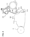
- Fig. 4 is an exploded front view of the main portion of the toner supply unit in the developing device.
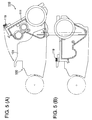
- Fig. 5 is a front view of the main portion of the developing device wherein the toner supply unit is combined with the developing unit to be opened or closed.
- Fig. 1 is a general structural diagram of an electrophotographic copying machine equipped with a developing device of the invention. An outline of the structure and function of the electrophotographic copying machine will be explained as follows, referring to the diagrams.
- platen glass 1 On the top of a main body of the copying machine, there is provided platen glass 1.
- light source 3 for exposure scans the document D for exposure thereof in a relative manner.
- Image light from the document D is converged by photographing lens 5 through moving mirror M1 that is united with the light source 3 and through moving mirrors M2 and M3 mounted on carriage 4 that travels simultaneously and relatively, and thereby is focused on the surface of photoreceptor drum 6 that is an image carrier to be an image further through fixed mirror M4.
- the photoreceptor drum 6 is composed of a metal cylinder that is grounded and a photoconductive layer made of selenium, OPC or the like formed on the outer circumferential surface of the metal cylinder, and it is rotated in the arrowed (clockwise) direction being linked to the scanning for exposure mentioned above.
- charging electrode 7 charge-elimination LED 8
- exposure/image-forming unit 9 developing unit 10
- transfer electrode 11 separation electrode 12
- separation claw 13 cleaning unit 14
- the photoconductive layer thereon mentioned above is uniformly charged to be positive, for example, by the charging electrode 7 on which DC high voltage is impressed, before the image light is focused to be an image.
- the photoconductive layer that is under the condition mentioned above receives the image light from the document D, the conductivity of the light-receiving portion is enhanced and thereby electric charges on the portion flow to the metal cylinder, thus, the positive charges remain on the dark portion depending on the degree of brightness. Accordingly, an electrostatic latent image corresponding to an image on the document is formed on the photoconductive layer. Then, the electrostatic latent image on the photoreceptor drum 6 is subjected to development by means of the developing unit 10 to be a toner image that is a visual image.
- the visual toner image on the photoreceptor drum 6 arrives at a transfer unit.
- transfer sheet P loaded on sheet-feeding cassette 20 is transported through first sheet-feeding roller 21, second sheet-feeding roller 22 and a guide plate and then is stopped temporarily by third sheet-feeding roller 23 and stopper 24. After that, the transfer sheet P is further transported in synchronization with the rotation of the photoreceptor drum 6 to reach the circumference of the photoreceptor drum 6, and the toner image on the photoreceptor drum 6 is transferred onto the transfer sheet P at a transfer section.
- the transfer sheet P fed to the transfer section is brought into close contact with the surface of the photoreceptor drum 6 and is subjected to discharging by means of the transfer electrode 11 in the polarity opposite to that of the toner, thus, the toner image is transferred onto the transfer sheet P.
- the transfer sheet P on which the toner image has been transferred is then separated from the surface of the photoreceptor drum 6 by means of the separation electrode 12 and the separation claw 13 and is further transported to arrive at fixing unit 25 where the transfer sheet P is subjected to heating and fixing by means of a heating roller.
- the transfer sheet P is then ejected by sheet-ejecting roller 26 to be delivered on delivery tray 27.
- toner staying on the surface of the photoreceptor drum 6 from which the transfer sheet P has been separated is removed by the cleaning unit 14 and remaining electric charges on the surface of the photoreceptor drum 6 are further removed by the pre-charging exposure unit 15 so that the photoreceptor drum may return to its original state. After that, the processes identical to those stated above are repeated for the next image formation.
- Fig. 2 is a sectional view of an image forming process unit in the copying machine mentioned above.
- the developing device 10 mentioned above is roughly composed of developing unit 100 and toner supply unit 110.
- rotatably developing roller 102 Inside casing 101 of the developing unit 100, there are supported rotatably developing roller 102, main agitating member 103 and auxiliary agitating member 104. Further, brush-height-regulating plate 105 is provided above the developing roller 102 and toner concentration detection sensor 106 is provided below the auxiliary agitating member 104.
- cartridge-accepting chamber 112 Inside casing 111 of the toner supply unit 110, there are provided cartridge-accepting chamber 112 into which or from which toner cartridge 120 containing toner to be supplied can be loaded or unloaded, a toner carrying-out means consisting of ladder wheel 113 that rakes out toner accumulated on the bottom of the casing 111 upward, ladder chain 114 and toner scraping-up member 115, toner supply screw 116 and remaining toner amount detection sensor 117.
- Electric power transferred between a main body of the copying machine and developing device 10 such as high voltage current for bias to be impressed upon developing roller 102 in the course of developing and detection current of toner concentration detection sensor 106 as well as that of remaining toner amount detection sensor 117 are supplied from a power supply unit and a control unit.
- toner to be supplied is carried out upward by the aforementioned toner carrying-out means in the toner supply unit 110 and is dropped from an opening of the casing 111 through the rotation of the toner supply screw 116. Then, the dropped toner is agitated and transported together with developer through the rotation of the auxiliary agitating member 104 of the developing unit 100 located below, and is further agitated and mixed by the main agitating member 103 so that one part thereof may be supplied to the developing roller 102 and the other part thereof may be supplied to the auxiliary agitating member 104.
- Fig. 3 is a sectional view showing the opened developing unit 100 in the invention.
- developer-pouring opening 101A is provided above the main agitating member 103 and at the upper portion of the casing 101 of the above-mentioned developing unit 100, and toner supply unit 110 is supported by interlocking members so that the toner supply unit 110 can revolve around the developing unit 100, thus, the opening 101A is opened when the toner supply unit 110 is revolved with the interlocking member as a center.
- the periphery of the opening 101A is sealed with elastic pads 108 and 118 and when the copying machine is in use, the pads 108 and 118 cause the casings 101 and 111 to be in pressure contact so that the opening 101A can be kept to be airtight.
- the elastic pad 108 attached on a peripheral portion on one side of the opening 101A of the developing unit 100 is brought into pressure contact with casing 111 of the toner supply unit 110, while the elastic pad 118 glued on the end portion of the casing 111 of the toner supply unit 110 is brought into pressure contact with a peripheral portion on the other side of the opening 101A.
- Fig. 4 is an exploded front view of the main portion of the developing unit 100 and toner supply unit 110.
- the lower and outer wall surface of the guide wall 101B is formed to be circular arc convex curved surface 101C.
- Both of the circular arc convex curved surface 101C and the concave curved surface 111B represent a circular arc curved surface having mostly the same radius.
- the cutout 111A on the casing 111 allows the above-mentioned guide wall 101B to pass through the cutout and thereby casings 101 and 111 respectively for the developing unit 100 and the toner supply unit 110 are linked rotatably to be free for opening or closing in the vicinity of the lower point.
- Fig. 5 (A) is a front view wherein the toner supply unit 110 is inclined by loosening clamping screw 119 and thereby the opening 101A is opened. Under this condition, developer is poured.
- Fig. 5 (B) represents the condition wherein the toner supply unit 110 is swung to close the opening and the clamping screw 119 is tightened so that the toner supply unit may be united to the developing unit 100 and the opening 101A is sealed hermetically.
- the opening 101A on the casing 101 is closed by being pressed and sealed by the casing 111 of the toner supply unit 110 and by elastic pads 108 and 118. Further, under the condition, the flux of image light L passes through the space above both of the developing unit 100 and the toner supply unit 110 and arrives at an area where an image is formed on the photoreceptor drum 6 through exposure.
- photoreceptor drum 6, charging electrode 7, charge-elimination LED 8, developing unit 10, separation claw 13 and cleaning unit 14 are provided on a frame to constitute a unitized image process unit.
- the process unit is supported on rack rails 19A and 19B in a manner that it can be drawn out of the main body of a copying machine.
- a supply unit through which developer is poured to be supplied is one for using two-component developers.
- the supply unit for developer can be applied also to a developing device employing single-component developers.
- a fresh developer into a developing unit in a developing device of the invention For supplying a fresh developer into a developing unit in a developing device of the invention, when a toner supply unit is caused to swing, an opening located at the upper portion of the developing unit is made to be in its opened state. Therefore, a fresh toner poured onto a main agitating member of the developing unit directly through the opening can be contained in the developing unit surely without flowing out or scattering. Accordingly, it is possible to supply developers easily, quickly and surely without necessity of separating and attaching the toner supply unit. And, it is easy to discharge developer from the opening.
Landscapes
- Physics & Mathematics (AREA)
- General Physics & Mathematics (AREA)
- Dry Development In Electrophotography (AREA)
Applications Claiming Priority (2)
| Application Number | Priority Date | Filing Date | Title |
|---|---|---|---|
| JP128794/92 | 1992-05-21 | ||
| JP4128794A JPH05323784A (ja) | 1992-05-21 | 1992-05-21 | 現像装置 |
Publications (2)
| Publication Number | Publication Date |
|---|---|
| EP0571136A2 true EP0571136A2 (de) | 1993-11-24 |
| EP0571136A3 EP0571136A3 (de) | 1994-01-05 |
Family
ID=14993612
Family Applications (1)
| Application Number | Title | Priority Date | Filing Date |
|---|---|---|---|
| EP19930303724 Withdrawn EP0571136A3 (de) | 1992-05-21 | 1993-05-14 | Entwicklungsvorrichtung mit einer Toner-Zuführeinheit |
Country Status (3)
| Country | Link |
|---|---|
| US (1) | US5426484A (de) |
| EP (1) | EP0571136A3 (de) |
| JP (1) | JPH05323784A (de) |
Cited By (1)
| Publication number | Priority date | Publication date | Assignee | Title |
|---|---|---|---|---|
| EP0715225A1 (de) * | 1994-11-30 | 1996-06-05 | Sharp Kabushiki Kaisha | Entwicklungsgerät |
Family Cites Families (9)
| Publication number | Priority date | Publication date | Assignee | Title |
|---|---|---|---|---|
| US4870463A (en) * | 1987-03-02 | 1989-09-26 | Mita Industrial Co., Ltd. | Latent electrostatic image developing device and toner cartridge |
| US4913087A (en) * | 1987-07-16 | 1990-04-03 | Sharp Kabushiki Kaisha | Developing device of a copier |
| US5075724A (en) * | 1988-08-26 | 1991-12-24 | Minolta Camera Kabushiki Kaisha | System for recognizing interchangeable articles |
| JPH0248965U (de) * | 1988-09-30 | 1990-04-05 | ||
| US5121165A (en) * | 1988-10-28 | 1992-06-09 | Mita Industrial Co., Ltd. | Developer unit and a toner hopper for an image forming device |
| JP2965041B2 (ja) * | 1988-11-08 | 1999-10-18 | 株式会社リコー | 画像形成装置 |
| JP2678084B2 (ja) * | 1990-08-31 | 1997-11-17 | シャープ株式会社 | 現像装置およびこれに利用される現像剤カートリツジ |
| US5260748A (en) * | 1990-12-14 | 1993-11-09 | Infographix, Inc. | Electrostatic image developer dispenser |
| KR940003109B1 (ko) * | 1991-04-17 | 1994-04-13 | 삼성전자 주식회사 | 화상 기록장치 |
-
1992
- 1992-05-21 JP JP4128794A patent/JPH05323784A/ja active Pending
-
1993
- 1993-05-13 US US08/061,220 patent/US5426484A/en not_active Expired - Fee Related
- 1993-05-14 EP EP19930303724 patent/EP0571136A3/de not_active Withdrawn
Cited By (2)
| Publication number | Priority date | Publication date | Assignee | Title |
|---|---|---|---|---|
| EP0715225A1 (de) * | 1994-11-30 | 1996-06-05 | Sharp Kabushiki Kaisha | Entwicklungsgerät |
| US5587777A (en) * | 1994-11-30 | 1996-12-24 | Sharp Kabushiki Kaisha | Developing unit having interlocking mechanism |
Also Published As
| Publication number | Publication date |
|---|---|
| JPH05323784A (ja) | 1993-12-07 |
| US5426484A (en) | 1995-06-20 |
| EP0571136A3 (de) | 1994-01-05 |
Similar Documents
| Publication | Publication Date | Title |
|---|---|---|
| US5638159A (en) | Developing unit for an image forming apparatus and method of collecting bicomponent developer therefrom | |
| US6556800B2 (en) | Developer supply container and image forming apparatus capable of mounting the container thereon | |
| US5182601A (en) | Image forming apparatus having toner handling units which are alternatively usable as a developing device or a cleaning device | |
| US5444515A (en) | Color image forming apparatus with mountable cartridge therein | |
| US4891673A (en) | Development system | |
| JP3576737B2 (ja) | カラー画像形成装置 | |
| US5426484A (en) | Conveyor housing having an opening which can be rendered in accessible by a toner housing | |
| US5140373A (en) | Electrostatic latent image developing apparatus with bristle height adjusting member | |
| US8073361B2 (en) | Preset case, development apparatus, process cartridge, and image forming apparatus | |
| JP3061711B2 (ja) | カラー画像記録装置 | |
| JP3904327B2 (ja) | トナー収容器及び画像形成装置 | |
| JPH10254225A (ja) | 画像形成装置 | |
| JP3295416B2 (ja) | カラー画像記録装置 | |
| JP3541568B2 (ja) | 画像形成装置 | |
| JPH0611966A (ja) | 現像剤補給装置 | |
| JP2514246B2 (ja) | 現像装置 | |
| JP3136148B1 (ja) | カラー画像記録装置 | |
| JPH04142562A (ja) | 画像形成装置 | |
| JPH08234551A (ja) | 画像形成装置 | |
| JPH04142565A (ja) | 画像形成装置の現像剤供給方法 | |
| JPH04366855A (ja) | 画像形成装置 | |
| JPS62208058A (ja) | 現像剤担持体の浮き上がりを防止した記録装置 | |
| JP3170399B2 (ja) | カラー画像記録装置 | |
| JP3323471B2 (ja) | カラー画像記録装置におけるユニット取り出し方法 | |
| JP3203243B2 (ja) | カラー画像記録装置 |
Legal Events
| Date | Code | Title | Description |
|---|---|---|---|
| PUAI | Public reference made under article 153(3) epc to a published international application that has entered the european phase |
Free format text: ORIGINAL CODE: 0009012 |
|
| PUAL | Search report despatched |
Free format text: ORIGINAL CODE: 0009013 |
|
| AK | Designated contracting states |
Kind code of ref document: A2 Designated state(s): DE FR GB IT NL |
|
| AK | Designated contracting states |
Kind code of ref document: A3 Designated state(s): DE FR GB IT NL |
|
| 17P | Request for examination filed |
Effective date: 19940609 |
|
| 17Q | First examination report despatched |
Effective date: 19951228 |
|
| GRAG | Despatch of communication of intention to grant |
Free format text: ORIGINAL CODE: EPIDOS AGRA |
|
| STAA | Information on the status of an ep patent application or granted ep patent |
Free format text: STATUS: THE APPLICATION HAS BEEN WITHDRAWN |
|
| 18W | Application withdrawn |
Withdrawal date: 19970530 |