EP0571159A1 - Registervorrichtung für Druckplatten - Google Patents
Registervorrichtung für Druckplatten Download PDFInfo
- Publication number
- EP0571159A1 EP0571159A1 EP93303786A EP93303786A EP0571159A1 EP 0571159 A1 EP0571159 A1 EP 0571159A1 EP 93303786 A EP93303786 A EP 93303786A EP 93303786 A EP93303786 A EP 93303786A EP 0571159 A1 EP0571159 A1 EP 0571159A1
- Authority
- EP
- European Patent Office
- Prior art keywords
- registration
- printing plate
- printing
- colour
- colours
- Prior art date
- Legal status (The legal status is an assumption and is not a legal conclusion. Google has not performed a legal analysis and makes no representation as to the accuracy of the status listed.)
- Withdrawn
Links
- 230000007246 mechanism Effects 0.000 claims abstract description 21
- 239000003086 colorant Substances 0.000 claims abstract description 17
- 238000012937 correction Methods 0.000 abstract description 4
- 238000006073 displacement reaction Methods 0.000 description 3
- 230000008878 coupling Effects 0.000 description 2
- 238000010168 coupling process Methods 0.000 description 2
- 238000005859 coupling reaction Methods 0.000 description 2
- 238000010586 diagram Methods 0.000 description 2
- 238000000034 method Methods 0.000 description 2
- 230000008569 process Effects 0.000 description 2
- 230000000712 assembly Effects 0.000 description 1
- 238000000429 assembly Methods 0.000 description 1
- 230000008901 benefit Effects 0.000 description 1
- 230000008859 change Effects 0.000 description 1
- 238000013481 data capture Methods 0.000 description 1
- 238000009434 installation Methods 0.000 description 1
- 239000000463 material Substances 0.000 description 1
Images

Classifications
-
- B—PERFORMING OPERATIONS; TRANSPORTING
- B41—PRINTING; LINING MACHINES; TYPEWRITERS; STAMPS
- B41F—PRINTING MACHINES OR PRESSES
- B41F13/00—Common details of rotary presses or machines
- B41F13/08—Cylinders
- B41F13/10—Forme cylinders
- B41F13/12—Registering devices
- B41F13/14—Registering devices with means for displacing the cylinders
Definitions
- the present invention relates to a multi-colour printing plate registration apparatus which may be retrofitted to existing printing presses.
- the individual colours are printed onto paper by separate printing plates (i.e. printing cylinders) under which the paper travels sequentially.
- printing plates i.e. printing cylinders
- Additional plate cylinders may be provided for printing special colours required for particular needs. Since the colours are printed individually, it is necessary to ensure that the printed images are in registration with one another in the finished printing. Thus, provision must be made for moving the plate cylinders in the X direction (i.e. transversely of the printing direction) and in the Y direction (i.e. circumferentially) relative to one another. In older printing presses, this is achieved manually by use of printing plate registration adjustment mechanisms which allow for adjustment in the X and Y directions. However, getting the correct adjustment tends to be a matter of experience and trial and error. On the other hand, modern computerised printing presses are provided with automatic computerised plate registration systems. However, such new equipment is expensive.
- the present invention provides a retro-fittable multi-colour printing plate registration apparatus which comprises:
- the drive means may be engageable with the existing registration adjustment mechanisms by means of gears on the drive means engageable with gears on the existing adjustment mechanisms.
- the drive means may comprise chain and sprocket means, belts, in-line couplings or other means known in the art.
- the drive means may include a servo motor, stepper motor, DC permanent magnet motor or other suitable motor for effecting movement of the plate cylinder.
- Sheets of colour printed material conventionally include registration marks for each colour, which are used to facilitate bringing the various colours into registration.
- the position of the registration marks is determined and digitised. This may be achieved by using a mouse to plot the registration marks on a computer grid, or by using a hand-held colour scanner to wand the registration marks, by using a colour CCD camera to capture the registration image, or by utilising cursor direction keys on the computer keyboard. In this way, the position of the individual registration marks can be plotted in both the X and Y directions and compared to nominal origin marks.
- the digital calculation means allow the actual positions of the registration marks to be compared with the in-register position and the necessary corrections to be calculated.
- the registration apparatus includes rotary encoders which allow the position of the plate cylinder to be determined and the correct amount of adjustment carried out using either a timed interval or a counted pulse duration.
- the digital calculation means is generally an IBM-compatible personal computer adapted for operation in an industrial situation and being capable of operating in an electrically noisy environment.
- the apparatus of the present invention will be required to control from 4 to 6 or more separate colour printing plates.
- the invention is particularly, though not exclusively, suitable for use with offset litho printing presses.
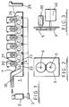
- Figure 1 shows an offset litho press 1 having a print housing 7. According to the invention, this is provided with a computer 2 and digital input/output cards 3 connected to motor/gearbox encoder assemblies 4.
- the press 1 comprises six sets of rollers for printing upto six colours. Each set comprises a plate cylinder 20 which carries the etched printing plate, from which the ink image is transferred onto a rubber coated blanket roller 21.
- the paper 24 to be printed passes from feeder 25 through the nip between blanket roller 21 and a smooth impression cylinder 23 where printing occurs. Roller 22 assists transfer of the paper.
- the multi-colour printed sheet leaves the press via delivery conveyor 26.
- Plate cylinder 20 is moved to bring the colours into registration.
- Figure 2 shows the shaft 6 of the plate cylinder 20 from which the conventional handwheel has been removed and replaced by a cog 8. This engages a drive cog 9 driven by motor 40.
- Figure 3 shows motor/gearbox drive means 40 for adjusting the position of the plate cylinder, together with a rotary encoder 10 driven by cog 5 for controlling the movement of the motor according to information fed to and from the computer.
- Figure 4 shows plate cylinders 14 and indicates the movement of the lateral X adjustment and circumferential Y adjustment.
- Figure 5 shows cogs 12, 13 (having locking levers 30, 31) which respectively control circumferential Y adjustment and lateral X adjustment in a conventional offset litho press. Control of the positioning of the printed image is achieved by turning the two cogs. Rotating the circumferential cog 12 in a clockwise direction advances the image on the printed sheet, whilst rotation in an anti-clockwise direction moves the image back on the printed sheet. Rotating the lateral cog 13 in a clockwise direction moves the image left on the printed sheet and rotation in an anti-clockwise direction moves the image to the right.
- these cogs are removed and replaced by gear wheels to allow the rotations to be carried out by the motor 40 under digital control.
- the present invention may be operated as follows.
- a sample sheet is printed and then placed on a measuring table or grid equipped with a magnifier (e.g. 20 x magnification) so that the registration marks of individual colours can be seen. Typically these may be out of registration by 0.025 to 3.5 mm.
- a magnifier e.g. 20 x magnification
- Data capture to log the position of the registration marks is effected either by manual data input via a mouse to plot the registration mark on a computer grid, or by using a hand-held colour scanner to wand the registration marks, by using a colour CCD camera to capture the registration image, or by utilising cursor direction keys on the computer keyboard.
- the registration marks are displayed on the computer registration grid and can be adjusted by using the mouse or the cursor direction keys.
- the system is provided with the new required plate position, plotted relative to a nominal origin in X and Y co-ordinates.
- the Y co-ordinate relates to the circumferential displacement and the X co-ordinate relates to the lateral displacement.
- the system accesses and recalls the plate positions.
- each co-ordinate is then multiplied by either a time or a pulse ratio which determines the adjustment factor for the motor.
- a negative value signifies an anti clockwise rotation, whilst the positive value signifies a clockwise rotation.
- the system then adds the plate displacements to the current plate positions held in the computer and updates the computer disc.
- Adjustment of the plates to bring the colours into registration may be performed simultaneously when the operator presses the "enter" button on the computer keyboard.
- the plates may be reset automatically to a central position when the operator presses the "CTRL-R" buttons.
- a second sample sheet will then be run to check that registration is correct before a print run is commenced.
- the present invention provides a registration apparatus which may be readily retrofitted to existing printing press installations, whilst requiring minimal changes thereto.
- FIGS 6 to 9 illustrate a practical embodiment of the invention applied to a typical printing press (Roland 800) having a manual plate registration mechanism, it being understood that the invention is equally applicable to other conventional printing press registration mechanisms. Analogous parts are indicated by the same reference numerals.
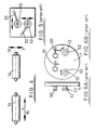
- Figures 6A and 6B show a conventional manual plate registration mechanism provided with a pair of handwheels 12,13 mounted on respective shafts 52,50 which are in turn connected to gear mechanisms (not shown) for effecting Y and X (rotation and transverse) movements respectively of the printing plate cylinders.
- the handwheels are locked by respective locking levers 30,31 which lock the handwheels via a locking mechanism (not shown).
- Figures 7A and 7B show the plate registration mechanism fitted with an apparatus according to the invention.
- the handwheels 12,13 have been removed to leave shafts 52,50.
- Onto shaft 50 is connected (via coupling 54) a servo 40 (e.g. a DC permanent magnet motor) mounted on a stub axle 56 having connected thereto a digital encoder 10.
- a similar servo-encoder assembly is also mounted on shaft 52 but is omitted for clarity.
- a pneumatic cylinder 58 having a rod 60 is mounted on the housing for operation of the locking lever 31.
- a similar assembly (not shown) is connected to the other locking lever 30.
- the rod 60 is pivotally connected to the end of lever 31 and is operated under pneumatic pressure to unlock the shaft 50 (and 52) prior to a plate registration operation, and then to lock the shaft again after registration is completed.
- Figure 8 is a view of screen 62 of computer 2 showing four crosses, each cross 63 representing the position of a registration mark of one of the four colours. These are plotted relative to a nominal origin, in this case the intersection of x and y axes 64,66.
- the computer calculates the corrections needed to bring the registration marks into alignment and applies these. When registration of all four plate cylinders is complete, the four crosses have moved together.
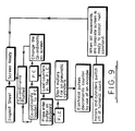
- Figure 9 is a block flow diagram showing the sequence of operations in a registration process. Briefly, the trial printed sheet is inspected and the co-ordinants of the four registration marks plotted on the computer screen (or the marks scanned and computer entry performed automatically). The computer (P.C.) then loads the counters in the programmable controller 3 (P.L.C.) which operates the pneumatic cylinders 58 to unlock the registration mechanisms on the four plate cylinders. The servo 40 is then operated to rotate shaft 50. Rotation of the shaft decrements the respective counter until the counter reaches zero when the required shaft movement is complete. The servo motors are then turned off and the pneumatic cylinders lock the shafts again. As the physical movements of the plate cylinders are undertaken, the crosses 63 on the screen move accordingly until they come into alignment when registration of the four plate cylinders is complete.
Landscapes
- Engineering & Computer Science (AREA)
- Mechanical Engineering (AREA)
- Inking, Control Or Cleaning Of Printing Machines (AREA)
Applications Claiming Priority (2)
| Application Number | Priority Date | Filing Date | Title |
|---|---|---|---|
| GB929210536A GB9210536D0 (en) | 1992-05-16 | 1992-05-16 | Printing plate registration apparatus |
| GB9210536 | 1992-05-16 |
Publications (1)
| Publication Number | Publication Date |
|---|---|
| EP0571159A1 true EP0571159A1 (de) | 1993-11-24 |
Family
ID=10715628
Family Applications (1)
| Application Number | Title | Priority Date | Filing Date |
|---|---|---|---|
| EP93303786A Withdrawn EP0571159A1 (de) | 1992-05-16 | 1993-05-17 | Registervorrichtung für Druckplatten |
Country Status (2)
| Country | Link |
|---|---|
| EP (1) | EP0571159A1 (de) |
| GB (1) | GB9210536D0 (de) |
Cited By (3)
| Publication number | Priority date | Publication date | Assignee | Title |
|---|---|---|---|---|
| WO1996004139A1 (en) * | 1994-08-05 | 1996-02-15 | Tetra Pak Manufacturing Pty. Ltd. | Alignment and affixing of printing plates |
| DE4434843A1 (de) * | 1994-09-29 | 1996-04-18 | Roland Man Druckmasch | Verfahren zur Vermeidung von Passerdifferenzen |
| AT402715B (de) * | 1994-06-30 | 1997-08-25 | Oesterr Forsch Seibersdorf | Anordnung zur einstellung von druckwalzen |
Citations (7)
| Publication number | Priority date | Publication date | Assignee | Title |
|---|---|---|---|---|
| US3525305A (en) * | 1967-06-20 | 1970-08-25 | American Type Founders Co Inc | Angular adjustment device for cylinder registering |
| FR2380137A1 (fr) * | 1977-02-10 | 1978-09-08 | Heidelberger Druckmasch Ag | Dispositif de reglage du reperage lateral et circonferentiel sur les machines a imprimer rotatives |
| GB2103788A (en) * | 1981-07-21 | 1983-02-23 | Komori Printing Mach | Unit-to-unit register adjusting apparatus of multicolor printing machine |
| DE3225165A1 (de) * | 1981-10-16 | 1983-04-28 | VEB Kombinat Polygraph "Werner Lamberz" Leipzig, DDR 7050 Leipzig | Verfahren und einrichtung zur fernbedienung von stellgliedern |
| EP0081186A1 (de) * | 1981-12-08 | 1983-06-15 | Heidelberger Druckmaschinen Aktiengesellschaft | Verfahren und Vorrichtung zur Verringerung von Registerfehlern bei Mehrfarben-Rotationsdruckmaschinen |
| EP0177885A2 (de) * | 1984-10-03 | 1986-04-16 | Dai Nippon Insatsu Kabushiki Kaisha | Verfahren und Vorrichtung zum Einstellen des Registers in Druckpressen |
| EP0422412A2 (de) * | 1989-10-09 | 1991-04-17 | Heidelberger Druckmaschinen Aktiengesellschaft | Vorrichtung und Verfahren zur Registerverstellung an einer Druckmaschine mit mehreren Druckwerken |
-
1992
- 1992-05-16 GB GB929210536A patent/GB9210536D0/en active Pending
-
1993
- 1993-05-17 EP EP93303786A patent/EP0571159A1/de not_active Withdrawn
Patent Citations (7)
| Publication number | Priority date | Publication date | Assignee | Title |
|---|---|---|---|---|
| US3525305A (en) * | 1967-06-20 | 1970-08-25 | American Type Founders Co Inc | Angular adjustment device for cylinder registering |
| FR2380137A1 (fr) * | 1977-02-10 | 1978-09-08 | Heidelberger Druckmasch Ag | Dispositif de reglage du reperage lateral et circonferentiel sur les machines a imprimer rotatives |
| GB2103788A (en) * | 1981-07-21 | 1983-02-23 | Komori Printing Mach | Unit-to-unit register adjusting apparatus of multicolor printing machine |
| DE3225165A1 (de) * | 1981-10-16 | 1983-04-28 | VEB Kombinat Polygraph "Werner Lamberz" Leipzig, DDR 7050 Leipzig | Verfahren und einrichtung zur fernbedienung von stellgliedern |
| EP0081186A1 (de) * | 1981-12-08 | 1983-06-15 | Heidelberger Druckmaschinen Aktiengesellschaft | Verfahren und Vorrichtung zur Verringerung von Registerfehlern bei Mehrfarben-Rotationsdruckmaschinen |
| EP0177885A2 (de) * | 1984-10-03 | 1986-04-16 | Dai Nippon Insatsu Kabushiki Kaisha | Verfahren und Vorrichtung zum Einstellen des Registers in Druckpressen |
| EP0422412A2 (de) * | 1989-10-09 | 1991-04-17 | Heidelberger Druckmaschinen Aktiengesellschaft | Vorrichtung und Verfahren zur Registerverstellung an einer Druckmaschine mit mehreren Druckwerken |
Cited By (4)
| Publication number | Priority date | Publication date | Assignee | Title |
|---|---|---|---|---|
| AT402715B (de) * | 1994-06-30 | 1997-08-25 | Oesterr Forsch Seibersdorf | Anordnung zur einstellung von druckwalzen |
| WO1996004139A1 (en) * | 1994-08-05 | 1996-02-15 | Tetra Pak Manufacturing Pty. Ltd. | Alignment and affixing of printing plates |
| DE4434843A1 (de) * | 1994-09-29 | 1996-04-18 | Roland Man Druckmasch | Verfahren zur Vermeidung von Passerdifferenzen |
| EP0709184A1 (de) | 1994-09-29 | 1996-05-01 | MAN Roland Druckmaschinen AG | Verfahren zur Vermeidung von Passerdifferenzen |
Also Published As
| Publication number | Publication date |
|---|---|
| GB9210536D0 (en) | 1992-07-01 |
Similar Documents
| Publication | Publication Date | Title |
|---|---|---|
| AU599693B2 (en) | Process and device for register correction | |
| EP0591792B1 (de) | Vorrichtung zum Abheben eines Zylinders | |
| DE102007057455B4 (de) | Druckmaschine mit Druckplattenmanipulationseinrichtung | |
| US5398603A (en) | Drive for a printing press with a plurality of printing units | |
| JP2005319788A (ja) | ロータリー多色プレスの彫刻シリンダーの位置合わせの初期調整のための方法と装置 | |
| DE4335351A1 (de) | Einrichtung zur Kompensation von Passerabweichungen bei Druckprodukten | |
| US5649484A (en) | Electronic apparatus and computer-controlled method for alignment correction | |
| CA1081039A (en) | Arrangement for the protection of a perfecting printing press | |
| DE4013003C2 (de) | Korrektur schrägliegender Druckbilder in einer Mehrfarbenbogendruckmaschine | |
| JPS63264355A (ja) | 見当合わせ装置 | |
| EP0747216B1 (de) | Steuerung für eine Druckmaschine | |
| EP0709184A1 (de) | Verfahren zur Vermeidung von Passerdifferenzen | |
| EP1314560B1 (de) | Druckmaschine | |
| DE4436102C2 (de) | Vorrichtung zur kontrollierten Übertragung von Druckfarbe | |
| DE19504585C2 (de) | Steuerung für eine Zylinderposition einer Druckmaschine | |
| US5421257A (en) | Sheet transferring machine for printing machine | |
| EP3280594A1 (de) | System zur registrierung der druckeinheiten einer rotationsdruckmaschine mit manuell einstellbarem druckregister | |
| DE10232111A1 (de) | Rotationsdruckmaschine | |
| EP1155844B1 (de) | Verfahren zur Einstellung des Registers bei einer Mehrfarbendruckmaschine | |
| US20010045167A1 (en) | Machine for processing printing-material sheets | |
| EP0658425A1 (de) | Bogenübertragungsvorrichtung für eine Druckmaschine | |
| DE4426992A1 (de) | Verfahren und Vorrichtung zur Zustandsüberwachung einer umstellbaren Bogendruckmaschine | |
| DE19548253B4 (de) | Verfahren und Einrichtung zur Korrektur des Umfangs-, Seiten- und Diagonalregisters | |
| JPH0327947A (ja) | 印刷機における見当量検出方法及びその装置 | |
| DE19520918A1 (de) | Steuerung für eine Druckmaschine |
Legal Events
| Date | Code | Title | Description |
|---|---|---|---|
| PUAI | Public reference made under article 153(3) epc to a published international application that has entered the european phase |
Free format text: ORIGINAL CODE: 0009012 |
|
| AK | Designated contracting states |
Kind code of ref document: A1 Designated state(s): AT BE CH DE DK ES FR GB GR IE IT LI LU MC NL PT SE |
|
| 17P | Request for examination filed |
Effective date: 19940524 |
|
| RBV | Designated contracting states (corrected) |
Designated state(s): AT BE CH DE DK ES FR GB GR IE IT LI LU NL PT SE |
|
| STAA | Information on the status of an ep patent application or granted ep patent |
Free format text: STATUS: THE APPLICATION IS DEEMED TO BE WITHDRAWN |
|
| 18D | Application deemed to be withdrawn |
Effective date: 19951201 |