EP0571165A1 - Binden von gelochten Bögen - Google Patents
Binden von gelochten Bögen Download PDFInfo
- Publication number
- EP0571165A1 EP0571165A1 EP93303804A EP93303804A EP0571165A1 EP 0571165 A1 EP0571165 A1 EP 0571165A1 EP 93303804 A EP93303804 A EP 93303804A EP 93303804 A EP93303804 A EP 93303804A EP 0571165 A1 EP0571165 A1 EP 0571165A1
- Authority
- EP
- European Patent Office
- Prior art keywords
- binding
- binding element
- pad
- insertion station
- perforations
- Prior art date
- Legal status (The legal status is an assumption and is not a legal conclusion. Google has not performed a legal analysis and makes no representation as to the accuracy of the status listed.)
- Granted
Links
- 238000003780 insertion Methods 0.000 claims abstract description 36
- 230000037431 insertion Effects 0.000 claims abstract description 36
- 239000002184 metal Substances 0.000 description 2
- 230000004323 axial length Effects 0.000 description 1
- 230000001419 dependent effect Effects 0.000 description 1
- 238000009434 installation Methods 0.000 description 1
- 238000012856 packing Methods 0.000 description 1
Images



Classifications
-
- B—PERFORMING OPERATIONS; TRANSPORTING
- B42—BOOKBINDING; ALBUMS; FILES; SPECIAL PRINTED MATTER
- B42B—PERMANENTLY ATTACHING TOGETHER SHEETS, QUIRES OR SIGNATURES OR PERMANENTLY ATTACHING OBJECTS THERETO
- B42B5/00—Permanently attaching together sheets, quires or signatures otherwise than by stitching
- B42B5/08—Permanently attaching together sheets, quires or signatures otherwise than by stitching by finger, claw or ring-like elements passing through the sheets, quires or signatures
- B42B5/10—Permanently attaching together sheets, quires or signatures otherwise than by stitching by finger, claw or ring-like elements passing through the sheets, quires or signatures the elements being of castellated or comb-like form
- B42B5/103—Devices for assembling the elements with the stack of sheets
Definitions
- This invention relates to apparatus for binding pads of perforated sheets to book form, such as, for example, notebooks, calendars, instruction manuals and the like, with wire binding elements.
- the wire binding elements for use with such apparatus are formed from a length of wire which is bent to form a series of curved, hair-pin shaped prongs.
- Each prong has a closed end, or "point”, an open end, or “root”, and a curved wall therebetween.
- the curvature of the prongs is such that the element has the appearance of an open-sided cylinder with a substantially C-shaped cross-section.
- binding elements will hereinafter be described as "binding elements of the type described”.
- a binding element of the type described is cut to a predetermined length and a pad of perforated sheets is moved relative to the binding element, or vice versa, so that the points of the binding element pass through the perforations.
- the binding element is then closed to ring shape by bringing its points into the vicinity of its roots thereby binding the pads.
- the step of aligning the pad of perforated sheets with the binding element and moving the pad so that the points of the binding elements pass through the perforations is commonly carried out automatically, see for example our prior British Patent No. 2213769.
- apparatus which can carry out this step reliably is complicated and expensive.
- it is often a requirement to bind pads of differing sizes with binding elements of varying sizes and apparatus which can meet this requirement is yet more complicated and expensive.
- binding apparatus in which at least the step of inserting the open binding elements into the perforations of a pad of sheets to be bound is carried out manually.
- Such apparatus is cheaper to produce than a fully automatic binding machine but leads to difficulty for the user, firstly in inserting the parts of the binding element into the perforations in the sheets to be bound and, secondly, in adjusting the apparatus for differing sizes of binding elements.
- Apparatus for binding pads of perforated sheets with wire binding elements of the type described in accordance with the invention comprises means for supplying a predetermined length of binding element to an insertion station, means for conveying a pad of perforated sheets having a binding element inserted through the perforations of the pad from the insertion station to a binding station and means for closing the binding element thereby binding the pad to book form, wherein the insertion station comprises means for holding the binding element in a predetermined position relative to a guide plate against which the edge of the pad of perforated sheets adjacent the perforations may be engaged to align the perforations with the points of the binding element present at the insertion station, so that the pad may readily be moved manually to a position in which the points of the binding element pass through the perforations.
- the guide plate in use may extend at least partially within the binding element and be pivotable about an axis substantially parallel to the axis of the binding element.
- the guide plate may be adjusted so that the perpendicular distance between the guide plate and the points of the binding element remains constant for different sizes of binding element.
- the manual steps of aligning the perforations with the points of the binding element and of moving the pad so that the points pass through the perforations may be carried out relatively quickly and repeatedly. Since the other steps in the binding operation may be carried out automatically, the throughput of the apparatus which is dictated by the skill and dexterity of the operator in carrying out the manual steps is significantly increased.
- the guide plate may be readily pivoted to accommodate pads having perforations located at different distances from the edge of the pad. In embodiments in accordance with the invention a binding rate in the region of 1000 pads of perforated sheets per hour has been achieved, the maximum binding rate being dependent upon the manual dexterity of the operator.
- the means for holding the binding element comprises a retainer plate parallel to the axis of the binding element and a transverse plate parallel to the axis and perpendicular to the retainer plate, the plates being disposed so that the roots and at least a part of the wall of the binding elements are supported in such a position that the binding element is correctly positioned relatively to the guide plate.
- Means may me provided to adjust the retainer plate and the transverse plate to accommodate different sizes of binding element and to hold such binding elements in the correct position to receive pads of perforated sheets.
- the apparatus may be rapidly adjusted so as to accommodate different sizes of binding element.
- the axis about which the guide plate is pivotable may suitably be fixed relative to the retainer plate.
- the retainer and transverse plates may be connected by a pivoting linkage member, the arrangement being such that as the retainer plate is adjusted, the transverse plate moves in the same direction by a distance a predetermined ratio of the distance moved by the retainer plate.
- the adjustment of the holding means to accommodate binding elements of different sizes within the insertion station may be quickly and easily carried out in apparatus in accordance with the invention, by pivoting the linkage member by a set amount.
- Means in the form of a toothed belt may be provided to convey the binding element into the insertion station.
- the belt assists in the accurate positioning and holding of the binding element within the insertion station.
- the dimensions and/or the pitch of the teeth of such a belt may be such that a single toothed belt may be used with a variety of sizes of binding element.
- Means may be provided to align at least one end of the edge of the pad of perforated sheets with the binding element in the insertion station. Such an arrangement enables the perforations in the pad of sheets to be aligned more easily and more rapidly with the points of the binding element.
- the metal wire to be used as a binding element is bent to form a series of curved hair-pin shaped prongs 28 having straight sections 29 therebetween.
- Each prong 28 has a point 26 and a root 27.
- the binding element 36 is curved to have a substantially C-shaped cross-section and forms an open-sided cylinder.
- the cylinder has a wall 34 opposite its open side and a depression 38 in the wall 34 running along the axial length of the binding element 36.
- the apparatus shown schematically in Figure 1 comprises a spool 1 of binding element 3 of the type described which is fed into a measuring and cutting device 7 by means of a sprocket 5.
- the device 7 measures a predetermined length of binding element and cuts it to a predetermined length.
- the cut length 15 of binding element is then conveyed to an insertion station 11 by means of an endless double-toothed belt 9 driven by a motor 21.
- a pad 13 of perforated sheets is moved by the operator so that the points 26 of the length 15 of binding element.
- the insertion station 11 will be described further below.
- the pad 13 having the length 15 of binding element inserted is then moved out of the insertion station 11, firstly by the toothed belt 9 and secondly by an endless pusher belt 17 having a number of pusher members 19.
- the pusher belt 17 is driven by the same motor 21 and at the same rate as the toothed belt 9.
- the pad 13 and length 15 of binding element are then moved into the binding station 23 to the position indicated at 13',15' by the pusher belt 17.
- the length 15' of binding element is closed to ring shape by pressing it between two platens, as will be described below, thereby binding the pad 13' to book form.
- the pusher belt 17 then conveys the bound pad 13',15' out of the binding station towards a conveyor 25 which then removes the bound pad 13',15' from the area of the apparatus 2 in the direction indicated by the arrow.
- a conveyor 25 which then removes the bound pad 13',15' from the area of the apparatus 2 in the direction indicated by the arrow.
- Any other suitable device (not shown) for use in the finishing of the bound pad 13',15', such as a cover turning unit, a shrink-wrapping unit, a boxing unit, a packing unit, or a combination of these, may be provided.
- a suitable replacement of the conveyor 25 may also be provided.
- the apparatus 2 is configured so that the operations at the measuring and cutting device 7, at the insertion station 11, and at the length 15 of binding station 23 are carried out simultaneously as pads 13 and binding element move through the apparatus.
- the feed of lengths 15 of binding element to the insertion station 11, and pads 15 into and through the apparatus is interrupted by the operator, by means of a foot pedal (not shown), so as to permit the operator time to carry out the insertion operation at the insertion station 11. Alternatively these feeds may be interrupted.
- the apparatus may also be halted to enable the operator to make adjustments so that different sizes of pad and/or of binding element may be accommodated in the apparatus 2.
- Figures 4a,4b and 4c show in greater detail, the insertion station 11 with different diameters of wire binding element 15a,15b,15c contained therein. All other references are common to each-of Figures 4a,4b and 4c.
- a length 15a of binding element has been moved into the insertion station 11 by toothed belt 9, the teeth of which engage the element between the prongs 28, and the roots 27 and part of the wall 34 of the length 15 of binding element are supported between toothed belt 9, which is supported by a fixed backing plate 42, retainer plate 41 and transverse plate 43.
- a guide plate 45 extends within the space enclosed by the binding element and is pivoted about axis 47. The guide plate 45 is rotated about the axis 47 so that the perpendicular distance 49 between the guide plate 45 and the points 26 of the binding element is equal to the distance between the edge of the pad 13 of perforated sheets and the perforations.
- the guide plate 45 may be pivoted about the axis 47 so that the distance 49 remains constant, as shown in Figures 4a,4b and 4c.
- the operator brings the edge of a pad 13 of perforated sheets to be bound (see also Fig. 1) into contact with the guide plate 45 so that the pad is substantially perpendicular thereto and slides the pad along the guide plate 45 towards the points 26. The pad is then lifted over the binding element with the points 26 passing through the perforations.
- the pad 13 and the length 15 of the binding-element are then conveyed out of the insertion station 11 by the toothed belt 9 and, via an idle station 20, into the binding station 23 (see Fig. 1) by the pusher belt 17 (Fig. 1) as described below.
- the pusher belt 17 preferably operates cyclically moving the pad 13 a set distance each cycle.
- the retainer plate 41 has an extension member 50 connected to a linkage member 51 by a sliding pivot 53.
- the transverse plate 43 is connected to the linkage member 51 by a further sliding pivot 55.
- the linkage member 51 is pivoted about a fulcrum 57 which is fixed in relation to the base 59 of the installation station 11.
- the distance between the sliding pivots 53,55 is such that as the linkage member 51 is rotated, the retainer plate 41 moves in the same direction as the transverse plate 43 and by a distance which is a predetermined ratio of the distance moved by the transverse plate 43 so as to accommodate different sizes of binding element between the retainer plate 41, the toothed belt 9 and the transverse plate 43 (see Figures 4b,4c).
- An adjustment device 61 (shown in Figure 4a only) is provided to pivot the linkage member 51 about the fulcrum 57, and this adjustment device 61 may have indicators or stops (not shown) so that the linkage member 51 may be rapidly moved between the positions necessary to accommodate particular sizes of binding element in the correct position in the insertion station.
- the axis 47 about which the guide plate 45 is pivoted is fixed in relation to the extension member 50.
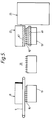
- the pad 13 and the length 15 of binding element are conveyed out of the insertion station 11 with the pad 13 hanging from the length 15 of binding element, the pad 13 is guided between a lower set of guide members 63b,65b (see Figure 6).
- One or both guide members is movable to accommodate different thicknesses of pad 13.
- the pad 13 and the length 15 of binding element are conveyed to the binding station 23 by the pusher belt 17 to the position shown at 13',15' where the binding element is closed to ring form by pressing it between a reciprocating platen 67 and a fixed platen 69, thereby binding the pad 13' to book form.
- the pad 13' Once the pad 13' has been bound, it is moved out of the binding station by the pusher belt 17 (not shown) onto the conveyor 25.
- a cylinder 71 is either manually or automatically operable to lift the pad 13' and element 15' so that the points 26 and roots 27 of the element 15' are pressed firmly against a backstop 73, the element 15' then being firmly held between the backstop 73 and the perforations in the pad 13' whilst the element 15' is closed between the platens 67,69.
Landscapes
- Engineering & Computer Science (AREA)
- Textile Engineering (AREA)
- Solid-Sorbent Or Filter-Aiding Compositions (AREA)
- Folding Of Thin Sheet-Like Materials, Special Discharging Devices, And Others (AREA)
Applications Claiming Priority (2)
| Application Number | Priority Date | Filing Date | Title |
|---|---|---|---|
| GB929210553A GB9210553D0 (en) | 1992-05-18 | 1992-05-18 | Improvements in and relating to binding perforated sheets |
| GB9210553 | 1992-05-18 |
Publications (2)
| Publication Number | Publication Date |
|---|---|
| EP0571165A1 true EP0571165A1 (de) | 1993-11-24 |
| EP0571165B1 EP0571165B1 (de) | 1996-12-27 |
Family
ID=10715644
Family Applications (1)
| Application Number | Title | Priority Date | Filing Date |
|---|---|---|---|
| EP93303804A Expired - Lifetime EP0571165B1 (de) | 1992-05-18 | 1993-05-17 | Binden von gelochten Bögen |
Country Status (5)
| Country | Link |
|---|---|
| US (1) | US5370489A (de) |
| EP (1) | EP0571165B1 (de) |
| AT (1) | ATE146726T1 (de) |
| DE (1) | DE69306856T2 (de) |
| GB (2) | GB9210553D0 (de) |
Cited By (3)
| Publication number | Priority date | Publication date | Assignee | Title |
|---|---|---|---|---|
| GB2291009A (en) * | 1994-07-14 | 1996-01-17 | Renz Chr Gmbh & Co | Method and apparatus for binding sheets |
| WO2002083427A1 (de) * | 2001-04-18 | 2002-10-24 | Attalus S.A. | Halbautomatisches drahtbindegerät |
| EP1211098A3 (de) * | 2000-11-29 | 2004-02-11 | Heidelberger Druckmaschinen Aktiengesellschaft | Verfahren zum Herstellen von Broschüren beliebiger Formate und Dicken mittels Drahtkammbindung |
Families Citing this family (14)
| Publication number | Priority date | Publication date | Assignee | Title |
|---|---|---|---|---|
| GB2301553B (en) * | 1995-05-04 | 1999-03-10 | Burn James Int Ltd | Improvements in and relating to a binding apparatus |
| GB9901990D0 (en) * | 1999-01-30 | 1999-03-17 | Smith Kevin | Improvememts in and relating to wire binding machines |
| AU2433501A (en) | 1999-12-17 | 2001-06-25 | General Binding Corporation | Binding apparatus |
| AU2002217778A1 (en) | 2000-11-22 | 2002-06-03 | General Binding Corporation | Plurality of binding elements for automated processes |
| US20020106265A1 (en) * | 2000-11-29 | 2002-08-08 | Mario Litsche | Binding apparatus and method |
| US20040240967A1 (en) | 2001-08-29 | 2004-12-02 | Phillip Crudo | Binding elements for binding a wide range of thicknesses of stacks of sheets |
| US20040018041A1 (en) * | 2001-11-20 | 2004-01-29 | Samuel Amdahl | Plurality of binding elements for automated processes |
| US6887025B2 (en) * | 2002-01-31 | 2005-05-03 | Performance Design, Inc. | Combined inserter and binder for wire element |
| US20030031502A1 (en) * | 2002-08-30 | 2003-02-13 | Rothschild Wayne H. | Binding element stacking structure |
| WO2005018949A2 (en) | 2003-08-11 | 2005-03-03 | General Binding Corporation | Binding elements and methods of forming binding elements |
| US20050238414A1 (en) * | 2004-04-16 | 2005-10-27 | General Binding Corporation | Disposable clip for coupling binding elements and combination of binding elements with disposable coupling clip |
| CA2573096A1 (en) * | 2004-07-12 | 2006-02-16 | General Binding Corporation | Binding element and plurality of binding elements particularly suited for automated processes |
| US8123448B2 (en) | 2005-08-16 | 2012-02-28 | General Binding Corporation | Apparatus and methods for automatically binding a stack of sheets with a nonspiral binding element |
| USD620977S1 (en) | 2006-08-04 | 2010-08-03 | General Binding Corporation | Binding element |
Citations (1)
| Publication number | Priority date | Publication date | Assignee | Title |
|---|---|---|---|---|
| DE3903506A1 (de) * | 1988-04-15 | 1989-10-26 | Sickinger Co | Halbautomatische bindevorrichtung |
Family Cites Families (6)
| Publication number | Priority date | Publication date | Assignee | Title |
|---|---|---|---|---|
| BE759219A (fr) * | 1969-11-20 | 1971-04-30 | Aglaghanian Jacques | Machine a relier semi-automatique |
| US4020516A (en) * | 1975-11-26 | 1977-05-03 | Spiral Binding Company, Inc. | Apparatus for binding loose sheets |
| US4155134A (en) * | 1978-03-31 | 1979-05-22 | Hans Sickinger Co. | Method and means for forming, inserting and closing zigzag wire binders |
| CH654528A5 (de) * | 1980-11-08 | 1986-02-28 | Womako Masch Konstr | Verfahren und vorrichtung zum herstellen von bloecken mit drahtkammbindung. |
| IT1151278B (it) * | 1982-06-04 | 1986-12-17 | Rilecart Spa | Macchina per la foratura e la rilegatura "a spirale" in modo automatico di blocchi di fogli e l'eventuale inserimento dei anci per la preparazione di calendari |
| US5090859A (en) * | 1990-02-20 | 1992-02-25 | General Binding Corporation | Automatic binding machine using insertion tools |
-
1992
- 1992-05-18 GB GB929210553A patent/GB9210553D0/en active Pending
-
1993
- 1993-05-17 US US08/062,429 patent/US5370489A/en not_active Expired - Lifetime
- 1993-05-17 DE DE69306856T patent/DE69306856T2/de not_active Expired - Fee Related
- 1993-05-17 AT AT93303804T patent/ATE146726T1/de not_active IP Right Cessation
- 1993-05-17 GB GB9310135A patent/GB2267460B/en not_active Expired - Fee Related
- 1993-05-17 EP EP93303804A patent/EP0571165B1/de not_active Expired - Lifetime
Patent Citations (1)
| Publication number | Priority date | Publication date | Assignee | Title |
|---|---|---|---|---|
| DE3903506A1 (de) * | 1988-04-15 | 1989-10-26 | Sickinger Co | Halbautomatische bindevorrichtung |
Cited By (3)
| Publication number | Priority date | Publication date | Assignee | Title |
|---|---|---|---|---|
| GB2291009A (en) * | 1994-07-14 | 1996-01-17 | Renz Chr Gmbh & Co | Method and apparatus for binding sheets |
| EP1211098A3 (de) * | 2000-11-29 | 2004-02-11 | Heidelberger Druckmaschinen Aktiengesellschaft | Verfahren zum Herstellen von Broschüren beliebiger Formate und Dicken mittels Drahtkammbindung |
| WO2002083427A1 (de) * | 2001-04-18 | 2002-10-24 | Attalus S.A. | Halbautomatisches drahtbindegerät |
Also Published As
| Publication number | Publication date |
|---|---|
| DE69306856T2 (de) | 1997-07-24 |
| GB9210553D0 (en) | 1992-07-01 |
| US5370489A (en) | 1994-12-06 |
| DE69306856D1 (de) | 1997-02-06 |
| EP0571165B1 (de) | 1996-12-27 |
| ATE146726T1 (de) | 1997-01-15 |
| GB9310135D0 (en) | 1993-06-30 |
| GB2267460A (en) | 1993-12-08 |
| GB2267460B (en) | 1995-12-20 |
Similar Documents
| Publication | Publication Date | Title |
|---|---|---|
| EP0571165B1 (de) | Binden von gelochten Bögen | |
| US4031585A (en) | Binding of perforated sheets | |
| US4874279A (en) | Semi-automatic binder | |
| US5921538A (en) | Apparatus and method for combined gathering and binding of sheet like articles | |
| JP2012086899A (ja) | 積み重ねられた製品を結束する結束システム及び方法 | |
| US3924664A (en) | Coil binding machine | |
| US20020090280A1 (en) | Coil spreader for spiral binding machines | |
| US3883916A (en) | Machines for binding packets of perforated sheets | |
| US3889309A (en) | Machines for binding packets of perforated sheets | |
| AU783529B2 (en) | Device for gathering flat articles into stacks and for further processing the stacks | |
| US5855464A (en) | Binding apparatus | |
| EP2043825B1 (de) | Ausgleichsgreifer mit unabhängiger greifereinstellung | |
| EP0095243A1 (de) | Drahtbindemaschinen | |
| US6769676B2 (en) | Apparatus for feeding spine inserts for the mechanical manufacture of book covers | |
| EP1491448A1 (de) | Zuführeinrichtung mit einem System zur automatischen Grössenerkennung. | |
| US4487538A (en) | Binding machines | |
| US3992002A (en) | Sheet registering apparatus | |
| US3972525A (en) | Sheet jogging assembly | |
| US4670083A (en) | Binder for bag pads | |
| JP3028084U (ja) | 選花機 | |
| JP6656659B2 (ja) | 用紙綴じ装置 | |
| US3114200A (en) | Apparatus for inserting and securing labels in printing plates | |
| US4571803A (en) | Fabrication apparatus for cushioned line support | |
| US7407356B2 (en) | Semi-automatic plastic spiral binding machine | |
| EP0201463A2 (de) | Tragvorrichtung für Zuführvorrichtung von Bogen oder dergleichen |
Legal Events
| Date | Code | Title | Description |
|---|---|---|---|
| PUAI | Public reference made under article 153(3) epc to a published international application that has entered the european phase |
Free format text: ORIGINAL CODE: 0009012 |
|
| AK | Designated contracting states |
Kind code of ref document: A1 Designated state(s): AT CH DE DK ES FR GB IE IT LI NL PT SE |
|
| 17P | Request for examination filed |
Effective date: 19940513 |
|
| 17Q | First examination report despatched |
Effective date: 19950907 |
|
| GRAG | Despatch of communication of intention to grant |
Free format text: ORIGINAL CODE: EPIDOS AGRA |
|
| GRAH | Despatch of communication of intention to grant a patent |
Free format text: ORIGINAL CODE: EPIDOS IGRA |
|
| RBV | Designated contracting states (corrected) |
Designated state(s): AT CH DE DK ES FR IE IT LI NL PT SE |
|
| GRAH | Despatch of communication of intention to grant a patent |
Free format text: ORIGINAL CODE: EPIDOS IGRA |
|
| GRAA | (expected) grant |
Free format text: ORIGINAL CODE: 0009210 |
|
| AK | Designated contracting states |
Kind code of ref document: B1 Designated state(s): AT CH DE DK ES FR IE IT LI NL PT SE |
|
| PG25 | Lapsed in a contracting state [announced via postgrant information from national office to epo] |
Ref country code: NL Free format text: LAPSE BECAUSE OF FAILURE TO SUBMIT A TRANSLATION OF THE DESCRIPTION OR TO PAY THE FEE WITHIN THE PRESCRIBED TIME-LIMIT Effective date: 19961227 Ref country code: LI Effective date: 19961227 Ref country code: IT Free format text: LAPSE BECAUSE OF FAILURE TO SUBMIT A TRANSLATION OF THE DESCRIPTION OR TO PAY THE FEE WITHIN THE PRE;WARNING: LAPSES OF ITALIAN PATENTS WITH EFFECTIVE DATE BEFORE 2007 MAY HAVE OCCURRED AT ANY TIME BEFORE 2007. THE CORRECT EFFECTIVE DATE MAY BE DIFFERENT FROM THE ONE RECORDED.SCRIBED TIME-LIMIT Effective date: 19961227 Ref country code: ES Free format text: THE PATENT HAS BEEN ANNULLED BY A DECISION OF A NATIONAL AUTHORITY Effective date: 19961227 Ref country code: DK Effective date: 19961227 Ref country code: CH Effective date: 19961227 Ref country code: AT Effective date: 19961227 |
|
| REF | Corresponds to: |
Ref document number: 146726 Country of ref document: AT Date of ref document: 19970115 Kind code of ref document: T |
|
| REF | Corresponds to: |
Ref document number: 69306856 Country of ref document: DE Date of ref document: 19970206 |
|
| REG | Reference to a national code |
Ref country code: IE Ref legal event code: FG4D Free format text: 71244 |
|
| PG25 | Lapsed in a contracting state [announced via postgrant information from national office to epo] |
Ref country code: SE Effective date: 19970327 Ref country code: PT Effective date: 19970327 |
|
| ET | Fr: translation filed | ||
| PG25 | Lapsed in a contracting state [announced via postgrant information from national office to epo] |
Ref country code: IE Free format text: LAPSE BECAUSE OF NON-PAYMENT OF DUE FEES Effective date: 19970517 |
|
| NLV1 | Nl: lapsed or annulled due to failure to fulfill the requirements of art. 29p and 29m of the patents act | ||
| REG | Reference to a national code |
Ref country code: CH Ref legal event code: PL |
|
| PLBE | No opposition filed within time limit |
Free format text: ORIGINAL CODE: 0009261 |
|
| STAA | Information on the status of an ep patent application or granted ep patent |
Free format text: STATUS: NO OPPOSITION FILED WITHIN TIME LIMIT |
|
| 26N | No opposition filed | ||
| PGFP | Annual fee paid to national office [announced via postgrant information from national office to epo] |
Ref country code: FR Payment date: 20000510 Year of fee payment: 8 |
|
| PGFP | Annual fee paid to national office [announced via postgrant information from national office to epo] |
Ref country code: DE Payment date: 20000515 Year of fee payment: 8 |
|
| PG25 | Lapsed in a contracting state [announced via postgrant information from national office to epo] |
Ref country code: FR Free format text: LAPSE BECAUSE OF NON-PAYMENT OF DUE FEES Effective date: 20020131 |
|
| PG25 | Lapsed in a contracting state [announced via postgrant information from national office to epo] |
Ref country code: DE Free format text: LAPSE BECAUSE OF NON-PAYMENT OF DUE FEES Effective date: 20020301 |