EP0571275B1 - Steuervorrichtung für ein automatisches Stufengetriebe - Google Patents
Steuervorrichtung für ein automatisches Stufengetriebe Download PDFInfo
- Publication number
- EP0571275B1 EP0571275B1 EP93401279A EP93401279A EP0571275B1 EP 0571275 B1 EP0571275 B1 EP 0571275B1 EP 93401279 A EP93401279 A EP 93401279A EP 93401279 A EP93401279 A EP 93401279A EP 0571275 B1 EP0571275 B1 EP 0571275B1
- Authority
- EP
- European Patent Office
- Prior art keywords
- pressure
- control device
- slipping
- line pressure
- converter
- Prior art date
- Legal status (The legal status is an assumption and is not a legal conclusion. Google has not performed a legal analysis and makes no representation as to the accuracy of the status listed.)
- Expired - Lifetime
Links
- 230000005540 biological transmission Effects 0.000 claims description 30
- 230000033228 biological regulation Effects 0.000 claims description 9
- 238000004364 calculation method Methods 0.000 claims description 5
- 230000009467 reduction Effects 0.000 claims description 5
- 230000001105 regulatory effect Effects 0.000 claims description 5
- 230000010354 integration Effects 0.000 claims description 4
- 238000012545 processing Methods 0.000 claims description 3
- 230000004044 response Effects 0.000 claims description 2
- 230000008901 benefit Effects 0.000 description 6
- 230000002349 favourable effect Effects 0.000 description 5
- 238000013461 design Methods 0.000 description 3
- 238000001914 filtration Methods 0.000 description 3
- 230000000670 limiting effect Effects 0.000 description 3
- 230000001276 controlling effect Effects 0.000 description 2
- 230000000694 effects Effects 0.000 description 2
- 238000002347 injection Methods 0.000 description 2
- 239000007924 injection Substances 0.000 description 2
- 239000006096 absorbing agent Substances 0.000 description 1
- 125000002015 acyclic group Chemical group 0.000 description 1
- 230000008859 change Effects 0.000 description 1
- 230000021615 conjugation Effects 0.000 description 1
- 238000012937 correction Methods 0.000 description 1
- 238000010586 diagram Methods 0.000 description 1
- 230000001970 hydrokinetic effect Effects 0.000 description 1
- 238000005259 measurement Methods 0.000 description 1
- 238000000034 method Methods 0.000 description 1
- 238000003032 molecular docking Methods 0.000 description 1
- 230000001681 protective effect Effects 0.000 description 1
- 230000035939 shock Effects 0.000 description 1
- 238000004513 sizing Methods 0.000 description 1
- 230000008685 targeting Effects 0.000 description 1
Images


Classifications
-
- F—MECHANICAL ENGINEERING; LIGHTING; HEATING; WEAPONS; BLASTING
- F16—ENGINEERING ELEMENTS AND UNITS; GENERAL MEASURES FOR PRODUCING AND MAINTAINING EFFECTIVE FUNCTIONING OF MACHINES OR INSTALLATIONS; THERMAL INSULATION IN GENERAL
- F16H—GEARING
- F16H61/00—Control functions within control units of change-speed- or reversing-gearings for conveying rotary motion ; Control of exclusively fluid gearing, friction gearing, gearings with endless flexible members or other particular types of gearing
- F16H61/04—Smoothing ratio shift
- F16H61/06—Smoothing ratio shift by controlling rate of change of fluid pressure
- F16H61/061—Smoothing ratio shift by controlling rate of change of fluid pressure using electric control means
-
- F—MECHANICAL ENGINEERING; LIGHTING; HEATING; WEAPONS; BLASTING
- F16—ENGINEERING ELEMENTS AND UNITS; GENERAL MEASURES FOR PRODUCING AND MAINTAINING EFFECTIVE FUNCTIONING OF MACHINES OR INSTALLATIONS; THERMAL INSULATION IN GENERAL
- F16H—GEARING
- F16H61/00—Control functions within control units of change-speed- or reversing-gearings for conveying rotary motion ; Control of exclusively fluid gearing, friction gearing, gearings with endless flexible members or other particular types of gearing
- F16H61/14—Control of torque converter lock-up clutches
- F16H61/143—Control of torque converter lock-up clutches using electric control means
-
- F—MECHANICAL ENGINEERING; LIGHTING; HEATING; WEAPONS; BLASTING
- F16—ENGINEERING ELEMENTS AND UNITS; GENERAL MEASURES FOR PRODUCING AND MAINTAINING EFFECTIVE FUNCTIONING OF MACHINES OR INSTALLATIONS; THERMAL INSULATION IN GENERAL
- F16H—GEARING
- F16H61/00—Control functions within control units of change-speed- or reversing-gearings for conveying rotary motion ; Control of exclusively fluid gearing, friction gearing, gearings with endless flexible members or other particular types of gearing
- F16H61/14—Control of torque converter lock-up clutches
- F16H61/143—Control of torque converter lock-up clutches using electric control means
- F16H2061/145—Control of torque converter lock-up clutches using electric control means for controlling slip, e.g. approaching target slip value
-
- F—MECHANICAL ENGINEERING; LIGHTING; HEATING; WEAPONS; BLASTING
- F16—ENGINEERING ELEMENTS AND UNITS; GENERAL MEASURES FOR PRODUCING AND MAINTAINING EFFECTIVE FUNCTIONING OF MACHINES OR INSTALLATIONS; THERMAL INSULATION IN GENERAL
- F16H—GEARING
- F16H2200/00—Transmissions for multiple ratios
- F16H2200/003—Transmissions for multiple ratios characterised by the number of forward speeds
- F16H2200/0043—Transmissions for multiple ratios characterised by the number of forward speeds the gear ratios comprising four forward speeds
-
- F—MECHANICAL ENGINEERING; LIGHTING; HEATING; WEAPONS; BLASTING
- F16—ENGINEERING ELEMENTS AND UNITS; GENERAL MEASURES FOR PRODUCING AND MAINTAINING EFFECTIVE FUNCTIONING OF MACHINES OR INSTALLATIONS; THERMAL INSULATION IN GENERAL
- F16H—GEARING
- F16H59/00—Control inputs to control units of change-speed- or reversing-gearings for conveying rotary motion
- F16H59/36—Inputs being a function of speed
- F16H59/46—Inputs being a function of speed dependent on a comparison between speeds
-
- F—MECHANICAL ENGINEERING; LIGHTING; HEATING; WEAPONS; BLASTING
- F16—ENGINEERING ELEMENTS AND UNITS; GENERAL MEASURES FOR PRODUCING AND MAINTAINING EFFECTIVE FUNCTIONING OF MACHINES OR INSTALLATIONS; THERMAL INSULATION IN GENERAL
- F16H—GEARING
- F16H61/00—Control functions within control units of change-speed- or reversing-gearings for conveying rotary motion ; Control of exclusively fluid gearing, friction gearing, gearings with endless flexible members or other particular types of gearing
- F16H61/68—Control functions within control units of change-speed- or reversing-gearings for conveying rotary motion ; Control of exclusively fluid gearing, friction gearing, gearings with endless flexible members or other particular types of gearing specially adapted for stepped gearings
- F16H61/684—Control functions within control units of change-speed- or reversing-gearings for conveying rotary motion ; Control of exclusively fluid gearing, friction gearing, gearings with endless flexible members or other particular types of gearing specially adapted for stepped gearings without interruption of drive
- F16H61/686—Control functions within control units of change-speed- or reversing-gearings for conveying rotary motion ; Control of exclusively fluid gearing, friction gearing, gearings with endless flexible members or other particular types of gearing specially adapted for stepped gearings without interruption of drive with orbital gears
Definitions
- the present invention relates to the technical field of automatic transmissions with stepped reports comprising a hydraulic torque converter bridgeable on certain reports.
- the object of the invention is to provide an automatic transmission control device with stepped ratios making it possible to benefit from the advantages, in terms of filtering, provided by an instant cut limiter device with controlled slip, without falling into the constructive difficulties most often. insurmountable encountered in the design of converters with integrated sliding lock-up.
- the invention relates to a stepped ratio automatic transmission control device comprising a torque converter provided with bridging means, a planetary gear train, several hydraulic receivers ensuring the switching of the planetary gear, and a hydraulic distributor delivering a pressure of PL line, which selectively powers the receivers under the control of an electronic computer, according to information concerning the running of the vehicle equipped with the transmission.
- This device is characterized in that at least one switching element is dimensioned so as to be able to slide in a controlled manner, in particular when the converter is bridged, in response to a momentary decrease in line pressure, and in that this sliding is slaved, via the line pressure PL, to set values depending on the torque Cm and the speed of the motor ⁇ m.
- the bridging means integrated into the converter are controlled in all or nothing by the transmission computer.
- the converter is provided with an integrated torsional damper.
- the device comprises a pressure control system which delivers in real time a TON control signal to a modulating solenoid valve intended to momentarily lower the line pressure to allow the element to slide. of commutation.
- the regulation of the line pressure PL is controlled by the electronic computer of the transmission which receives information relating to the engine torque Cm, the engine speed ⁇ m and the turbine speed ⁇ t.
- a regulator makes it possible to calculate the pressure decrease ⁇ P VS L imposed on the set line pressure P VS L determined by the transmission computer so as to establish the line pressure setpoint during slip P VS L (gl) P VS L - ⁇ P VS L .
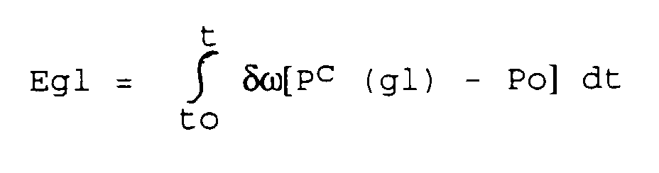
- a comparison unit calculates the difference between the set pressure P VS L (gl) and the docking pressure Po of the switching member, this difference being transmitted to a processing unit which performs its product by the instantaneous value of the slip ⁇ .
- an integration unit is capable of starting the calculation of the energy: proportional to the energy dissipated in the switching device from the start to of the sliding phase, each time ⁇ adopts a non-zero value.
- the exceeding by Egl of a preset threshold makes it possible to determine that the energy dissipated in the switching member during a sliding phase, has reached a level endangering endurance and the longevity of the friction linings thereof.
- the device comprises a main pressure regulating valve, balanced on one side by a first spring and on the other by the line pressure PL acting in feedback on a pusher and by the modulated control pressure Pm controlled by the modulating solenoid valve, acting, in the same direction as the line pressure PL, on the differential surface between the main control valve and the pusher.
- the device comprises a pressure reduction valve, delivering a supply pressure P 1 , balanced on one side by a second spring, and on the other side by the pressure of supply P 1 itself, brought into feedback through a first nozzle, to ensure its own regulation, the pressure P 1 ensuring, by means of a second nozzle, the supply of the modulating solenoid valve.
- the switching members comprise at least two clutches (E 1 , E 2 ) and three immobilization means (F 1 , F 2 , F 3 ) and the switching member biased by the slip is an E 2 clutch tightened at least on the three upper ratios of the transmission.
- the automatic transmission device illustrated in FIG. 1 conventionally has a hydraulic torque converter 1, associated with a planetary gear train 2 whose movement output crown 3 is connected to a differential 4.
- the planetary gear train 2 is a double planetary train, of which we can recognize in particular the two rings C 1 , C 2 and satellites S 1 , S 2 , belonging respectively to the first and to the second set of satellites.
- the planetary gear train 2 supports a sensor 28 of the turbine speed ⁇ t, aiming at a target 29.
- the switching members responsible for shifting the gear consist of two clutches E 1 , E 2 , and three immobilization means F 1 , F 2 , F 3, the switching table of which is the subject of FIG. 2.
- the invention consists, first of all, in dimensioning one or more switching elements of an automatic transmission in such a way that, for all the ratios on which it is desired to benefit from a torque limiting effect, the only one of the switching elements can slide slightly when the line pressure PL is lowered in a controlled manner: slippage is controlled by reference values depending on the torque Cm and the speed ⁇ m of the motor, by the line pressure PL, thus achieves the desired objective.
- the damper 7 could moreover be eliminated if the design of the clutch E 2 , 8 makes it possible in all cases to operate the linings of the clutch E 2 , 8, under sufficiently favorable conditions, and / or with engines with a high number of cylinders (greater than or equal to six in most cases).
- the pressure regulation implements a main pressure regulation valve 9, balanced, of a side, by a first spring 10, and on the other side by the regulated line pressure PL acting against feedback on a pusher 11 and by the modulated control pressure Pm acting on the differential surface 12 between the valve 9 and the pusher 11, in the same direction as the regulated pressure PL.
- a pressure reduction valve 13 delivering a supply pressure P 1 is balanced on one side by a second spring 14 and on the other side by the pressure P 1 itself, brought into feedback through a first nozzle 26, to ensure its own regulation at a constant value.
- This pressure P 1 is used to supply, through a second nozzle 27, the modulating solenoid valve 15 which determines the value of the modulated pressure Pm acting to the right on the surface differential 12 existing between the control valve 9 and the pusher 10.
- This modulated pressure Pm is in linear relation with the control signal TON of the modulating solenoid valve 15.
- the source of hydraulic power can be, without limitation, a pump 16 drawing from an oil reserve 17.
- the slippage control of the clutch E 2 consists in calculating in real time the value of TON which makes it possible to obtain the instantaneous line pressure level P L authorizing the desired slip of E 2 .
- the difference ⁇ c - ⁇ is sent to a PID 19 regulator - this type of regulator is naturally non-limiting - which calculates a correction ⁇ P VS L at setpoint P VS L developed for the pressure control system 21 by the automatic transmission computer.
- the pressure control system 21 which can be, in a nonlimiting manner, in accordance with that described in the publication FR-A-2 616 931 of the applicant produces the signal TON controlling the modulating solenoid valve 15.
- the various gains of the regulator 19 can be adjusted, depending on the gear N established, and also during gear changes.
- the energy Egl is proportional to the energy dissipated in the clutch E 2 from the start to of the sliding phase. S i Egl exceeds a threshold set in advance, this means that during the controlled slipping phase considered, the energy dissipated in the clutch E 2 has reached a level such that the endurance and durability of the friction linings risk being endangered, and it is therefore necessary to take protective measures (reduction of the authorized slip ⁇ c or downshift to the lower gear).
Landscapes
- Engineering & Computer Science (AREA)
- General Engineering & Computer Science (AREA)
- Mechanical Engineering (AREA)
- Physics & Mathematics (AREA)
- Fluid Mechanics (AREA)
- Control Of Transmission Device (AREA)
- Control Of Fluid Gearings (AREA)
- Control Of Driving Devices And Active Controlling Of Vehicle (AREA)
Claims (13)
- Steuervorrichtung für ein automatisches Stufengetriebe, mit einem Drehmomentwandler (1), der mit einer Überbrückungsanordnung (6,6') versehen ist, mit einem Planetengetriebe (2), mit mehreren hydraulischen Aufnehmern (Ei, Fi) zur Schaltung des Planetengetriebes (2) und mit einem hydraulischen Verteiler (16, 17), der einen Leitungsdruck PL zur Verfügung stellt, mit dem wahlweise die Aufnehmer (Ei,Fi) gespeist werden können, unter Steuerung eines elektronischen Rechners entsprechend den die Fahrt des mit dem Getriebe ausgerüsteten Fahrzeugs betreffenden Informationen, dadurch gekennzeichnet, daß wenigstens ein Schaltelement (8) derart bemessen ist, daß es in gesteuerter Weise gleiten kann, insbesondere, wenn der Wandler (1) überbrückt ist, in Abhängigkeit von einer momentanen Verringerung des Leitungsdrucks PL, und daß dieses Gleiten durch den Leitungsdruck PL gesteuert wird auf Einstellwerte, die vom Moment Cm und der Motorgeschwindigkeit ωm abhängen.
- Steuervorrichtung nach Anspruch 1, dadurch gekennzeichnet, daß die im Wandler integrierte Überbrückungsanordnung (6,6') vom Getrieberechner im Alles- oder Nichts-Verfahren gesteuert wird.
- Steuervorrichtung nach Ansprüchen 1 oder 2, dadurch gekennzeichnet, daß der Wandler (1) mit einem integrierten Torsionsdämpfer (7) versehen ist.
- Steuervorrichtung nach Ansprüchen 1, 2 oder 3, dadurch gekennzeichnet, daß sie ein Drucksteuersystem (21) aufweist, welches in Echtzeit ein Steuersignal TON einem modulierenden Elektroventil (15) zuführt, welches den Leitungsdruck momentan absenkt, um ein Gleiten des Schaltelementes (8) zu ermöglichen.
- Steuervorrichtung nach einem der vorhergehenden Ansprüche, dadurch gekennzeichnet, daß die Regelung des Leitungsdrucks PL gesteuert wird vom elektronischen Getrieberechner, welcher die Informationen bezüglich des Motormomentes Cm der Motorgeschwindigkeit ωm und der Turbinengeschwindigkeit ωt erhält.
- Steuervorrichtung nach einem der vorhergehenden Ansprüche, dadurch gekennzeichnet, daß die Steuerschleife des Gleitvorgangs es ermöglicht, den momentanen Gleitwert δω = ωm - ωt mit einem Gleiteinstellwert δωc (Cm, ωm) als Funktion der Hauptparameter Cm und ωm zu vergleichen und gegebenenfalls mit Sekundärparametern, wie z.B. dem eingelegten Gang N oder die Öltemperatur θh.
- Steuervorrichhtung nach Anspruch 6, dadurch gekennzeichnet, daß sie ein Steuergerät (19) aufweist, welches es ermöglicht, die Druckabnahme ΔPL c zu berechnen und diese beim Wert des Leitungsdrucks PL c, der vom Getrieberechner ermittelt wurde, zu berücksichtigen hinsichtlich der Erstellung eines Leitungsdruckwertes während des Gleitvorgangs von PL c (gl) = PL c - ΔPL c.
- Steuervorrichtung nach Anspruch 7, dadurch gekennzeichnet, daß sie eine Vergleichereinheit (22) aufweist, welche die Berechnung der Differenz zwischen dem Einstelldruck Pc (gl) und dem Kupplungsdruck Po des Schaltteils ausführt, wobei diese Differenz einer Verarbeitungseinheit (24) zugeführt wird, welche ihr Produkt mit dem momentanen Gleitwert δω bildet.
- Steuervorrichtung nach Anspruch 8, dadurch gekennzeichnet, daß sie eine Integriereinheit (25) aufweist, die in der Lage ist, die folgende Energieberechnung durchzuführen:
- Steuervorrichtung nach Anspruch 9, dadurch gekennzeichnet, daß das Überschreiten von Egl eines vorgegebenen Schwellwertes es ermöglicht, zu bestimmen, daß die im Schaltteil (8) während einer Gleitphase in Wärme umgewandelte Energie ein Niveau erreicht hat, welches die Haltbarkeit und die Lebensdauer ihrer Reibbeläge beeinträchtigt.
- Steuervorrichtung nach einem der Ansprüche 4 bis 10, dadurch gekennzeichnet, daß sie ein Hauptventil zur Drucksteuerung (9) aufweist, das sich im Gleichgewicht befindet, einerseits durch eine erste Feder (10) und andererseits durch den gesteuerten Druck PL, der wiederum auf einen Schieber (11) wirkt und durch den modulierten Steuerdruck Pm, der durch das modulierende Elektroventil (15) gesteuert wird, und der in gleicher Richtung wie der Leitungsdruck PL auf die Differentialfläche (12) wirkt, welche zwischen dem Hauptventil der Steuerung (9) und dem Schieber (10) vorhanden ist.
- Steuervorrichtung nach Anspruch 11, dadurch gekennzeichnet, daß sie ein Druckreduzierventil (13) aufweist, welches einen Versorgungsdruck P1 liefert, und das sich im Gleichgewicht befindet, einerseits durch eine zweite Feder (14) und andererseits durch den Druck P1, der wiederum durch eine erste Engstelle (26) hindurch eine Gegenwirkung ausübt im Hinblick auf seine eigene Steuerung, um dadurch die Speisung des modulierenden Elektroventils (15) durch eine zweite Engstelle (27) hindurch zu ermöglichen.
- Steuervorrichtung nach einem der vorhergehenden Ansprüche, dadurch gekennzeichnet, daß die Schaltteile wenigstens zwei Kupplungen (E1, E2) und wenigstens drei Feststellanordnungen (F1, F2, F3) aufweisen, und daß das durch den Gleitvorgang beaufschlagte Schaltteil eine Kupplung E2 ist, die mit wenigstens den drei höchsten Gängen des Getriebes verbunden ist.
Applications Claiming Priority (2)
| Application Number | Priority Date | Filing Date | Title |
|---|---|---|---|
| FR9206035 | 1992-05-19 | ||
| FR929206035A FR2691516B1 (fr) | 1992-05-19 | 1992-05-19 | Dispositif de controle de transmission automatique a rapports etages. |
Publications (2)
| Publication Number | Publication Date |
|---|---|
| EP0571275A1 EP0571275A1 (de) | 1993-11-24 |
| EP0571275B1 true EP0571275B1 (de) | 1996-07-03 |
Family
ID=9429910
Family Applications (1)
| Application Number | Title | Priority Date | Filing Date |
|---|---|---|---|
| EP93401279A Expired - Lifetime EP0571275B1 (de) | 1992-05-19 | 1993-05-18 | Steuervorrichtung für ein automatisches Stufengetriebe |
Country Status (5)
| Country | Link |
|---|---|
| US (1) | US5409426A (de) |
| EP (1) | EP0571275B1 (de) |
| JP (1) | JP3459839B2 (de) |
| DE (1) | DE69303431T2 (de) |
| FR (1) | FR2691516B1 (de) |
Families Citing this family (13)
| Publication number | Priority date | Publication date | Assignee | Title |
|---|---|---|---|---|
| DE19504847B4 (de) * | 1994-02-23 | 2006-04-27 | Luk Gs Verwaltungs Kg | Überwachungsverfahren für ein Drehmoment-Übertragungssystem eines Kraftfahrzeugs |
| US5507372A (en) * | 1994-06-13 | 1996-04-16 | Eaton Corporation | Torque converter slip rate-based torque converter lock-up strategy |
| JP2799957B2 (ja) * | 1994-10-27 | 1998-09-21 | セイコークロック株式会社 | El発光針 |
| US5725456A (en) * | 1994-10-29 | 1998-03-10 | Luk Getriebe Systeme Gmbh | Method of regulating the operation of a torque transmission apparatus |
| FR2741129B1 (fr) * | 1995-11-10 | 1998-01-09 | Renault | Mecanisme de changement de vitesses automatique a rapports etages |
| DE19735820B4 (de) | 1997-08-18 | 2005-08-18 | Daimlerchrysler Ag | Schaltvorrichtung eines Wechselgetriebes mit Druckregelventilen für den Arbeitsdruck und einen Versorgungsdruck |
| JP2004124964A (ja) * | 2002-09-30 | 2004-04-22 | Jatco Ltd | 自動変速機の油圧制御装置およびロックアップコントロールバルブ |
| JP4848864B2 (ja) * | 2006-07-07 | 2011-12-28 | マツダ株式会社 | 車両の振動低減装置 |
| US8010265B2 (en) | 2007-12-07 | 2011-08-30 | GM Global Technology Operations LLC | Effective driveline vibration detection algorithm in transmission TCC slip control |
| DE102008002295A1 (de) * | 2008-06-09 | 2009-12-10 | Zf Friedrichshafen Ag | Mehrgruppengetriebe eines Kraftfahrzeuges |
| JP6028585B2 (ja) * | 2013-01-17 | 2016-11-16 | トヨタ自動車株式会社 | 動力伝達装置の制御装置 |
| JP6673261B2 (ja) * | 2017-02-24 | 2020-03-25 | トヨタ自動車株式会社 | 車両の変速制御装置 |
| US10315632B2 (en) * | 2017-10-12 | 2019-06-11 | GM Global Technology Operations LLC | Dual mass flywheel protection by software |
Family Cites Families (20)
| Publication number | Priority date | Publication date | Assignee | Title |
|---|---|---|---|---|
| US4457411A (en) * | 1980-06-02 | 1984-07-03 | Mitsubishi Jidosha Kogyo Kabushiki Kaisha | Torque transmission device |
| FR2543242B1 (fr) * | 1983-03-22 | 1989-03-31 | Renault | Commande de la pression d'alimentation d'un recepteur hydraulique |
| FR2570458B1 (fr) * | 1984-09-18 | 1990-03-02 | Renault | Dispositif et procedes de commande d'une transmission automatique a quatre rapports |
| US4724939A (en) * | 1986-07-17 | 1988-02-16 | General Motors Corporation | Closed loop clutch slip control system with turbine roughness control |
| US4757886A (en) * | 1987-01-20 | 1988-07-19 | Ford Motor Company | Transmission clutch closed loop slip controller and method |
| JPS63303257A (ja) * | 1987-05-30 | 1988-12-09 | Fuji Heavy Ind Ltd | ロックアップクラッチの制御装置 |
| US4880090A (en) * | 1987-06-11 | 1989-11-14 | Aisin-Warner Kabushiki Kaisha | Hydraulic controlling system for lockup clutches |
| US4957194A (en) * | 1987-09-08 | 1990-09-18 | Mazda Motor Corporation | Torque converter slip control device |
| US4805750A (en) * | 1987-09-28 | 1989-02-21 | Saturn Corporation | Steady state slip detection/correction for a motor vehicle transmission |
| JPH0242268A (ja) * | 1988-08-01 | 1990-02-13 | Nissan Motor Co Ltd | パワートレーンの総合制御装置 |
| JP2685288B2 (ja) * | 1989-05-10 | 1997-12-03 | マツダ株式会社 | 流体継手のスリップ制御装置 |
| US5029087A (en) * | 1989-07-24 | 1991-07-02 | Ford Motor Company | Electronic control system for controlling torque converter bypass clutches |
| JP2825289B2 (ja) * | 1989-10-16 | 1998-11-18 | マツダ株式会社 | 流体継手のスリップ制御装置 |
| JP2925698B2 (ja) * | 1990-09-27 | 1999-07-28 | マツダ株式会社 | 流体継手の締結力制御装置 |
| JP2929711B2 (ja) * | 1990-11-27 | 1999-08-03 | 日産自動車株式会社 | 自動変速機のロックアップ制御装置 |
| JPH0530610U (ja) * | 1991-10-02 | 1993-04-23 | 日本電子機器株式会社 | 車両用自動変速機の制御装置 |
| JPH05133469A (ja) * | 1991-11-11 | 1993-05-28 | Japan Electron Control Syst Co Ltd | 車両用自動変速機の制御装置 |
| US5303616A (en) * | 1992-08-10 | 1994-04-19 | Ford Motor Company | Electronically controlled bypass clutch based on percent-shift-completion for a torque converter |
| US5323320A (en) * | 1992-09-17 | 1994-06-21 | Ford Motor Company | Stability test for slip operation of torque converter clutch |
| US5291979A (en) * | 1993-01-12 | 1994-03-08 | Jatco Corporation | Automatic transmission lockup clutch control apparatus |
-
1992
- 1992-05-19 FR FR929206035A patent/FR2691516B1/fr not_active Expired - Lifetime
-
1993
- 1993-05-18 EP EP93401279A patent/EP0571275B1/de not_active Expired - Lifetime
- 1993-05-18 DE DE69303431T patent/DE69303431T2/de not_active Expired - Lifetime
- 1993-05-19 JP JP11693293A patent/JP3459839B2/ja not_active Expired - Lifetime
- 1993-05-19 US US08/063,468 patent/US5409426A/en not_active Expired - Lifetime
Also Published As
| Publication number | Publication date |
|---|---|
| FR2691516B1 (fr) | 1994-07-01 |
| FR2691516A1 (fr) | 1993-11-26 |
| DE69303431D1 (de) | 1996-08-08 |
| JP3459839B2 (ja) | 2003-10-27 |
| JPH0634035A (ja) | 1994-02-08 |
| US5409426A (en) | 1995-04-25 |
| DE69303431T2 (de) | 1997-01-23 |
| EP0571275A1 (de) | 1993-11-24 |
Similar Documents
| Publication | Publication Date | Title |
|---|---|---|
| EP0571275B1 (de) | Steuervorrichtung für ein automatisches Stufengetriebe | |
| FR2764664A1 (fr) | Procede pour commander un systeme de transmission de couple et dispositifs pour sa mise en oeuvre | |
| FR2736407A1 (fr) | Embrayage de pontage pour convertisseur hydrodynamique et procedes de commande d'un systeme de transmission de couple comprenant ledit embrayage | |
| EP0021258B1 (de) | Elektronische Überbrückungssteuerung eines hydrodynamischen Drehmomentwandlers und Anwendungsverfahren | |
| EP1563207B1 (de) | Auswahlverfahren für die übersetzung eines automatischen getriebes | |
| FR2487742A1 (fr) | Systeme de transmission de couple | |
| FR2694061A1 (fr) | Boîte de vitesses variable en continu; dispositif et stratégies de commande pour le servomécanisme de son réa secondaire. | |
| FR2828144A1 (fr) | Appareil de commande de changement de vitesse d'une transmission automatique de vehicule a moteur | |
| FR2785961A1 (fr) | Vehicule automobile comportant une boite de vitesses a changements de rapports automatises | |
| FR2853036A1 (fr) | Systeme de commande pour un mecanisme de transmission de puissance | |
| EP1633999B1 (de) | Kooperatives steuerungssystem für einen antriebsmotor und ein stufenloses getriebe eines fahrzeugs | |
| FR2570458A1 (fr) | Dispositif et procedes de commande d'une transmission automatique a quatre rapports | |
| FR2698138A1 (fr) | Système pour refroidir un embrayage de démarrage d'une boîte de vitesse variable en continu. | |
| FR2512404A1 (fr) | Dispositif de commande du rapport de couple pour une transmission par courroie a variation continue pour vehicules | |
| EP0026115B1 (de) | Hydrostatische Getriebe mit grossem Betriebsbereich | |
| US6345223B1 (en) | Lock-up control device for vehicle | |
| FR2647060A1 (fr) | Installation motrice pour vehicule amphibie | |
| EP4069540B1 (de) | Verfahren zum kompensieren von drehmomenterzeugungsfehlern eines verbrennungsmotors in einem hybrid-antriebsstrang | |
| FR2697784A1 (fr) | Procédé et dispositif de commande pour augmenter le ralenti d'un véhicule marchant au point mort. | |
| EP3658434B1 (de) | Verfahren zur steuerung von gangwechseln in phasen von regenerativem bremsen | |
| FR2879705A1 (fr) | Dispositif et procede de synchronisation pour boites de vitesses de type "double embrayage" | |
| EP0249529B1 (de) | Kraftübertragungseinrichtung für Brandbekämpfungsfahrzeug | |
| FR2795791A1 (fr) | Vehicule automobile possedant un dispositif d'actionnement automatise de l'embrayage | |
| WO2000071380A1 (fr) | Procede et dispositif de pilotage d'un embrayage de boîte de vitesses manuelle robotisee | |
| FR2651465A1 (fr) | Dispositif de transmission pour vehicule de lutte contre l'incendie. |
Legal Events
| Date | Code | Title | Description |
|---|---|---|---|
| PUAI | Public reference made under article 153(3) epc to a published international application that has entered the european phase |
Free format text: ORIGINAL CODE: 0009012 |
|
| AK | Designated contracting states |
Kind code of ref document: A1 Designated state(s): DE ES GB IT |
|
| 17P | Request for examination filed |
Effective date: 19940503 |
|
| 17Q | First examination report despatched |
Effective date: 19950612 |
|
| GRAH | Despatch of communication of intention to grant a patent |
Free format text: ORIGINAL CODE: EPIDOS IGRA |
|
| GRAH | Despatch of communication of intention to grant a patent |
Free format text: ORIGINAL CODE: EPIDOS IGRA |
|
| GRAA | (expected) grant |
Free format text: ORIGINAL CODE: 0009210 |
|
| AK | Designated contracting states |
Kind code of ref document: B1 Designated state(s): DE ES GB IT |
|
| PG25 | Lapsed in a contracting state [announced via postgrant information from national office to epo] |
Ref country code: ES Free format text: THE PATENT HAS BEEN ANNULLED BY A DECISION OF A NATIONAL AUTHORITY Effective date: 19960703 |
|
| ITF | It: translation for a ep patent filed | ||
| REF | Corresponds to: |
Ref document number: 69303431 Country of ref document: DE Date of ref document: 19960808 |
|
| GBT | Gb: translation of ep patent filed (gb section 77(6)(a)/1977) |
Effective date: 19960905 |
|
| PLBE | No opposition filed within time limit |
Free format text: ORIGINAL CODE: 0009261 |
|
| STAA | Information on the status of an ep patent application or granted ep patent |
Free format text: STATUS: NO OPPOSITION FILED WITHIN TIME LIMIT |
|
| 26N | No opposition filed | ||
| REG | Reference to a national code |
Ref country code: GB Ref legal event code: IF02 |
|
| PGFP | Annual fee paid to national office [announced via postgrant information from national office to epo] |
Ref country code: DE Payment date: 20120523 Year of fee payment: 20 |
|
| PGFP | Annual fee paid to national office [announced via postgrant information from national office to epo] |
Ref country code: GB Payment date: 20120522 Year of fee payment: 20 |
|
| PGFP | Annual fee paid to national office [announced via postgrant information from national office to epo] |
Ref country code: IT Payment date: 20120529 Year of fee payment: 20 |
|
| REG | Reference to a national code |
Ref country code: DE Ref legal event code: R071 Ref document number: 69303431 Country of ref document: DE |
|
| REG | Reference to a national code |
Ref country code: GB Ref legal event code: PE20 Expiry date: 20130517 |
|
| PG25 | Lapsed in a contracting state [announced via postgrant information from national office to epo] |
Ref country code: DE Free format text: LAPSE BECAUSE OF EXPIRATION OF PROTECTION Effective date: 20130522 Ref country code: GB Free format text: LAPSE BECAUSE OF EXPIRATION OF PROTECTION Effective date: 20130517 |