EP0571333B1 - Armlehne für Kraftfahrzeugsitze - Google Patents
Armlehne für Kraftfahrzeugsitze Download PDFInfo
- Publication number
- EP0571333B1 EP0571333B1 EP93830028A EP93830028A EP0571333B1 EP 0571333 B1 EP0571333 B1 EP 0571333B1 EP 93830028 A EP93830028 A EP 93830028A EP 93830028 A EP93830028 A EP 93830028A EP 0571333 B1 EP0571333 B1 EP 0571333B1
- Authority
- EP
- European Patent Office
- Prior art keywords
- shaft
- arm rest
- end portion
- tubular
- axial
- Prior art date
- Legal status (The legal status is an assumption and is not a legal conclusion. Google has not performed a legal analysis and makes no representation as to the accuracy of the status listed.)
- Expired - Lifetime
Links
- 229910052751 metal Inorganic materials 0.000 claims description 10
- 239000002184 metal Substances 0.000 claims description 9
- 238000006073 displacement reaction Methods 0.000 claims description 8
- 239000000463 material Substances 0.000 claims description 7
- 230000002093 peripheral effect Effects 0.000 claims description 5
- 230000000295 complement effect Effects 0.000 claims description 2
- 230000001105 regulatory effect Effects 0.000 description 3
- 238000003780 insertion Methods 0.000 description 2
- 230000037431 insertion Effects 0.000 description 2
- 230000005540 biological transmission Effects 0.000 description 1
- 238000006243 chemical reaction Methods 0.000 description 1
- 238000010276 construction Methods 0.000 description 1
- 230000001788 irregular Effects 0.000 description 1
- 230000010355 oscillation Effects 0.000 description 1
- 230000001681 protective effect Effects 0.000 description 1
- 238000009877 rendering Methods 0.000 description 1
Images




Classifications
-
- B—PERFORMING OPERATIONS; TRANSPORTING
- B60—VEHICLES IN GENERAL
- B60N—SEATS SPECIALLY ADAPTED FOR VEHICLES; VEHICLE PASSENGER ACCOMMODATION NOT OTHERWISE PROVIDED FOR
- B60N2/00—Seats specially adapted for vehicles; Arrangement or mounting of seats in vehicles
- B60N2/75—Arm-rests
- B60N2/753—Arm-rests movable to an inoperative position
-
- B—PERFORMING OPERATIONS; TRANSPORTING
- B60—VEHICLES IN GENERAL
- B60N—SEATS SPECIALLY ADAPTED FOR VEHICLES; VEHICLE PASSENGER ACCOMMODATION NOT OTHERWISE PROVIDED FOR
- B60N2/00—Seats specially adapted for vehicles; Arrangement or mounting of seats in vehicles
- B60N2/75—Arm-rests
- B60N2/763—Arm-rests adjustable
-
- Y—GENERAL TAGGING OF NEW TECHNOLOGICAL DEVELOPMENTS; GENERAL TAGGING OF CROSS-SECTIONAL TECHNOLOGIES SPANNING OVER SEVERAL SECTIONS OF THE IPC; TECHNICAL SUBJECTS COVERED BY FORMER USPC CROSS-REFERENCE ART COLLECTIONS [XRACs] AND DIGESTS
- Y10—TECHNICAL SUBJECTS COVERED BY FORMER USPC
- Y10T—TECHNICAL SUBJECTS COVERED BY FORMER US CLASSIFICATION
- Y10T403/00—Joints and connections
- Y10T403/32—Articulated members
- Y10T403/32254—Lockable at fixed position
- Y10T403/32426—Plural distinct positions
Definitions
- the present invention refers to arm rests for motor vehicle seats, particularly front seats having a backrest with lateral sides, of the type comprising an elongated body and a load bearing structure incorporated in the body and including swinging mounting means of the arm rest comprising a connecting element adapted to be fixed relative to a lateral side of the backrest, a tubular end portion of the load bearing structure oriented transverse to the body, and a shaft coaxially inserted within the said tubular end portion and having one end projecting from the body and secured to the said connecting element so as to allow rotation on the said shaft of the tubular end portion of the load bearing structure between a raised position and a lowered position of the arm rest, and stop means for stopping rotation of the arm rest in the said raised and lowered positions.
- An arm rest of the above-mentioned type is generally known from US-A-4 067 613.
- This known arm rest is freely rotatable between the raised and lowered positions, with the risk of undesired displacement.
- an arm rest provided with a locking mechanism to stop rotation thereof in the raised and, respectively, in the lowered position.
- This locking mechanism includes an outer stationary arcuate slot and a stopper pin projecting laterally from the arm rest and having elastic walls cooperating with catching apertures formed at the upper and lower ends of the slot.
- the primary object of the present invention is to provide an improved arm rest of the above-mentioned type.
- a further object of the invention is to provide an arm rest of this type which, in use, is displaceable from the raised position to the lowered position and viceversa only in a controlled way, and which therefore is free from the risk of sudden and undesired displacement from the raised to the lowered position.
- Still another object of the invention is to provide an arm rest of reliable and safe operation and adapted to be manufactured in a relatively simple and cheap way.
- an arm rest for motor vehicle seats of the type defined at the beginning characterized in that the tubular end portion of the load bearing structure has an elastically deformable conformation in a radial direction and is internally formed with a pair of opposed axial ribs and with a pair of longitudinal recesses placed on opposite sides of an adiacent to each of the said ribs, and in that the shaft is exteriorly provided with a pair of opposed rigid axial projections cooperating with the said axial ribs so as to constitute the said stop means; the said axial projections of the shaft having an outer radial dimension which is substantially corresponding to the inner radial dimension of the said longitudinal recesses of the said tubular end portion of the load bearing structure and which is substantially greater than the inner radial dimension of the said tubular end portion between the longitudinal recesses adiacent to each other.
- the arm rest is provided with manual regulating means for modifying the angular position of the shaft relative to the connecting element.
- Such regulating means allow adjusting the slant of the arm rest in the lowered position as a function of the user's need, maintaining the said slant even following displacement of the arm rest to the raised position and successive return to the lowered position.
- the arm rest further comprises disengageable locking means for angularly locking the said tubular end portion of the load bearing structure relative to the shaft in the raised position of the arm rest.
- reference numeral 1 generally indicates as a whole an arm rest according to the invention, particularly adapted to be applied on one lateral side F of the backrest B of a motor vehicle front seat.
- the arm rest 1 is swingably cantilever supported by the side F of the backrest B, in the way clarified hereinafter, between an operative lowered position shown with continous line in figure 1, in which it extends substantially horizontally aside the backrest B, and an inoperative raised position, shown with dotted lines in the same figure, in which it extends upwardly and substantially parallel to the side F of the backrest B.
- the arm rest 1 comprises an elongated body 2 normally made of foamed plastic material with an outer covering 3 and incorporating a load bearing structure 4, formed by a substantially U-shaped metallic element 10 rigidly connected, normally by overmoulding on the free ends of the branches thereof, to a tubular end portion 5 made of plastic material, oriented transverse to the body 2 and provided with exterior stiffening elements 6.
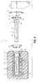
- the tubular end portion 5 is rotatably mounted on a support shaft generally indicated as 7, which is coaxially fitted within the tubular end portion 5 and projects from one side thereof, through a corresponding opening 8 of the elongated body 2, for its connection in a stationary condition to the side F of the backrest B, by means of a shaped connecting plate 9.
- the shaft 7 is constituted by an inner metal core 11 having a polygonal, normally exagonal cross section, and by an outer tubular body 12 of plastic material, overmoulded on the metal core 11.
- the outer tubular body 12 is formed with a pair of opposed rigid axial projections 13, radially protruding outwardly and terminating, in proximity of the outer end of the shaft 7, into an enlarged portion 14 formed with a peripheral groove 15 and in turn terminating with an enlarged annular collar 16.
- the collar 16 is at least partially hollow and is provided with a plurality (three in the example shown in the drawings) of axial bores 17 within which respective metal bushes 18 are inserted.
- the inner metal core 11 of the shaft 7 axially projects at one end 11a from the enlarged collar 16 in order to engage, with the interposition of a protective annular cover 19, a corresponding polygonal throughhole 20 formed in the connecting element 9.
- the connecting element 9 is constituted by a sturdy reinforced metal plate mechanically connected, by means of any conventional system, to the structure of the backrest B, in correspondence of the lateral edge F thereof.
- Fixing of the shaft 7 relative to the connecting element 9 is accomplished, following the introduction of the end 11a of the metal core 11 through the hole 20, by fastening screws 21 axially fitted within the bushes 17 of the enlarged collar 16.
- the protection cover 19 is axially held between the collar 16, on one side, and the connecting element 9 on the other side.
- the end 11a of the metal core 11 and the throughhole 20 of the connecting element 9 can be conveniently provided with an irregular pentagonal cross section, such as shown in figure 13.
- the tubular end portion 5 of the load bearing structure 4, which is open in correspondence of one end 22 thereof (facing the opening 8 of the body 2) so as to allow insertion of the shaft 7 therein, has an inner wall 23 which is relatively deformable elastically, by virtue of a relatively reduced thickness thereof and of the intrinsic characteristic of the material constituting the said tubular portion 5.
- the wall 23 is formed interiorly with a pair of opposed axial ribs 24 and with a pair of longitudinal recesses 25 disposed on opposite side of and adiacent to each of the ribs 24.
- Each of the recesses 25 has a radial dimension substantially corresponding to that of the axial projections 13 of the shaft 7, while the two wall portions 26 comprised between each pair of adiacent recesses 25 have an inner radial dimension slightly lower than the outer radial dimension of the axial projections 13.
- the shaft 7 is coaxially inserted within the tubular end portion 5, through the open end 22 thereof and the opening 8 of the body 2, with the interposition of an annular protection cover 27.
- the axial locking between the tubular end portion 5 and the shaft 7 is simply accomplished by means of an open-ring spring 28 mounted on the open end 22 in correspondence of a slit 29 thereof and engaging the peripheral groove 15 of the outer tubular body 12 of the shaft 7.
- the tubular end portion 5, and thus the whole body 2 of the arm rest 1 are rotatable on the shaft 7 so as to allow angular displacement thereof between the lowered position and the raised position.
- the oscillation angular travel of the body 2 is limited by the stop of the axial projections 13 of the shaft 7 on one side and on the opposite side relative to the axial ribs 24 of the tubular end portion 5. In both positions the projections 13 engage the corresponding recesses 25, so as to ensure a firm positioning of the arm rest 1.
- the arm rest 1 is further provided with a manual regulating device for varying the inclination thereof relative to the backrest B, in the lowered condition, between the positions shown for example in figure 7, as well as with a disengageable locking device for locking thereof in the raised position, shown with dotted lines in figure 7.
- the openings of the enlarged collar 16 of the outer tubular body 12 of the shaft 7 for insertion of the axial screws 21 are in this case constituted by slots 30, and the said enlarged collar 16 is angularly displaceable relative to the screws 21 for the angular width of the said slots 30.
- the enlarged collar 16 is formed with a peripheral radial notch 31, having a substantially semicircular shape, housing therein a cam member 32 having a complementary shape and carried by a tubular slide 33 slidably mounted substantially vertically along a guide portion 34 formed in a box-like body 35 interposed between the enlarged collar 16 and the connecting element 9.
- the box 35 rotatably supports an operating shaft 36 coaxial with the slide 33 and formed with a screw 37 engaging an innerly threaded bush 50 and the lower end of which is connected in a freely rotatable way to the slide 33.
- the shaft 36 projects superiorly from the box 35 with a manually operable driving plug 38, the rotation of which causes the translation of the slide 33 and consequently, by means of the engagement between the cam member 32 and the notch 31 of the enlarged collar 16, angular adjustment of the shaft 7, or in other words adjustment of the slant of the body 2 of the arm rest 1 relative to the backrest B of the seat.
- the angular locking of the shaft 7 in the set position is performed by the cam member 32, acting as a latch within the notch 31 of the collar 16.
- plug 38 could be substituted by an endless belt drive and associated gear transmission, not shown.
- the locking device in the raised position is shown in details in figures 9 through 12. It comprises a push button 39, normally of plastic material, having a grip end 40 projecting below the box-like body 35 and formed superiorly with a fork portion 41 slidably supported vertically in correspondence of a pair of lateral projections 42 protruding from opposite sides of the enlarged portion 14 of the outer tubular body 12 of the shaft 7.
- the push button 39 incorporates a L-shaped hook tooth 43, normally metallic, slidably guided along a lower radial slit 44 of the enlarged portion 14.
- An annular plastic material body 45 provided with a metal reinforce 46 and shown in detail in figure 11, is applied on the open end 22 of the tubular end portion 5 of the load bearing structure 4. Moreover, the open end 22 is formed with a radial notch 47 adapted to be engaged, in the way disclosed hereinafter, by the hook tooth 43.
- the push button 39 is subject to the action of a plate spring 48, having a substantially triangular shape as shown in detail in figure 12, reacting against the lower surface of the end 11a of the core 11 of the shaft 7.
- the opening 47 of the open end 22 of the tubular end portion 5 is angularly positioned such as shown in figure 11, i.e. at an angle of about 90° clockwise relative to the hook tooth 43, with reference to such figure.
- the push button 39 is maintained in a raised condition within the opening 44 of the enlarged portion 14, against the reaction of the spring 48, into abutment against the inner wall of the open end 22.
Landscapes
- Engineering & Computer Science (AREA)
- Aviation & Aerospace Engineering (AREA)
- Transportation (AREA)
- Mechanical Engineering (AREA)
- Seats For Vehicles (AREA)
- Chairs For Special Purposes, Such As Reclining Chairs (AREA)
Claims (8)
- Armstütze (1) für Sitze eines Kraftfahrzeuges mit einer Rückenlehne (B) mit seitlichen Seiten (F), mit einem langgestreckten Körper (2) und einer in dem Körper (2) inkorporierten Lastaufnahmestruktur (4) sowie einer verschwenkbaren Befestigungseinrichtung für die Armstütze (1) mit einem Verbindungselement (9), welches zur Befestigung relativ an einer seitlichen Seite (F) der Rückenlehne (B) ausgebildet ist, einem rohrförmigen Endabschnitt (5) der Lastaufnahmestruktur (4), der quer zum Körper (2) ausgerichtet ist und einer koaxial in dem rohrförmigen Endabschnitt (5) eingesetzten Achse (7) mit einem aus dem Körper (2) hervorstehenden Ende (11a), welches an dem Verbindungselement (9) festgelegt ist, damit eine Drehung der Achse (7) des rohrförmigen Endabschnittes (5) zwischen einer angehobenen Stellung und einer abgesenkten Stellung der Armstütze möglich ist und mit einer Stoppeinrichtung zum Stoppen der Bewegung der Armstütze (1) in der angehobenen und der abgesenkten Stellung, dadurch gekennzeichnet, daß der rohrförmige Endabschnitt (5) eine elastisch verformbare Gestaltung (23) in radialer Richtung besitzt und an seiner Innenseite mit einem Paar sich gegenüberliegender axialer Rippen (24) und mit einem Paar langgestreckter Vertiefungen (25) an gegenüberliegenden Seiten und benachbart zu jeder der Rippen (24) ausgebildet ist und daß die Achse (7) außen mit einem Paar von gegenüberliegenden starren axialen Vorsprüngen (13) versehen ist, welche mit den axialen Rippen (24) zur Bildung der Stoppeinrichtung zusammenwirken; die axialen Vorsprünge (13) der Achse (7) eine äußere radiale Abmessung besitzen, welche weitgehend der inneren radialen Abmessung der langgestreckten Vertiefungen (25) des rohrförmigen Endabschnittes (5) der Lastaufnahmestruktur (4) entspricht und die wesentlich größer ist als die innere radiale Abmessung (26) des rohrförmigen Endabschnittes (5) zwischen den einander benachbarten langgestreckten Vertiefungen (25).
- Armstütze nach Anspruch 1, dadurch gekennzeichnet, daß die Achse (7) von einem inneren Metallkern (11) mit einem polygonalen Querschnitt und einem äußeren rohrförmigen Körper (12) aus einem auf den Kern (11) aufgeformten und mit den gegenüberliegenden axialen Vorsprüngen (13) ausgebildeten Kunststoffwerkstoff gebildet ist, wobei der Kern (11) einen Endstück-Abschnitt (11a) besitzt, welcher aus dem äußeren rohrförmigen Körper (12) entsprechend dem einen Ende der Achse (7) hervorsteht und mit einer Öffnung (20) mit einer zu dem Verbindungselement (9) komplementären Form in Eingriff steht.
- Armstütze nach Anspruch 1, dadurch gekennzeichnet, daß sie eine Einrichtung zur axialen Festlegung der Achse (7) relativ zu dem rohrförmigen Endabschnitt (5) der Lastaufnahmestruktur (4) besitzt mit einer offenen Ringfeder (28), die entsprechend einem Schlitz (29) des rohrförmigen Endabschnittes (5) angeordnet ist und mit einer entsprechenden Nut (15), welche an dem äußeren rohrförmigen Körper (12) der Achse (7) nahe dessen einen Ende (11a) ausgebildet ist, in Eingriff steht.
- Armstütze nach Anspruch 3, dadurch gekennzeichnet, daß der äußere rohrförmige Körper (12) der Achse (7) entsprechend deren einem Ende (11a) mit einem ringförmigen Bund (16) ausgebildet ist, der mit axialen Bohrungen (17) versehen ist, durch die hindurch axiale Befestigungsschrauben (21) der Achse (7) an dem Verbindungselement (9) angeordnet sind.
- Armstütze nach Anspruch 4, dadurch gekennzeichnet, daß die Axialbohrungen (17) langgestreckte Schlitze (30) sind und daß die Armstütze (1) mit einer manuellen Einstelleinrichtung (33, 36, 38) zur Veränderung der Winkelstellung der Achse (7) relativ zu den Befestigungsschrauben (21) versehen ist.
- Armstütze nach Anspruch 5, dadurch gekennzeichnet, daß die Einstelleinrichtung eine äußere Kerbe (31) aufweist, welche an dem ringförmigen Bund (16) des äußeren rohrförmigen Körpers (12) der Achse (7) ausgebildet ist, ein Nockenglied (32) besitzt, welches weitgehend radial mit der äußeren Kerbe (31) im Eingriff steht, einen einem Gehäuse ähnlichen Körper (35) aufweist, welcher zwischen dem Körper (2) der Armstütze (1) und dem Verbindungselement (9) angeordnet ist, ein rohrförmiges Gleitstück (33) besitzt, welches das Nockenglied (32) trägt und verschiebbar in dem gehäuseähnlichen Körper (35) geführt ist und eine Antriebswelle (36) aufweist, die von dem gehäuseähnlichen Körper (35) zur Steuerung des Versatzes des rohrförmigen Gleitstückes (33) abgestützt ist.
- Armstütze nach Anspruch 1, dadurch gekennzeichnet, daß sie weiterhin eine lösbare Einrichtung (39) zur winkeligen Verriegelung des rohrförmigen Endabschnittes (5) der Lastaufnahmestruktur (4) relativ zu der Achse (7) in der angehobenen Stellung der Armstütze (1) aufweist.
- Armstütze nach Anspruch 7, dadurch gekennzeichnet, daß die lösbare Verriegelungseinrichtung einen dem einen Ende (11a) der Achse (7) zugeordneten Druckknopf (39) besitzt, welcher radial relativ zu dieser zwischen einer zurückgezogenen Verriegelungsstellung und einer nach vorne bewegten, die Verriegelung lösenden Stellung verschiebbar ist, wobei der Druckknopf (37) einen hakenförmigen Zahn (43) besitzt, welcher in der angehobenen Stellung der Armstütze (1) mit einem radialen Sitz (47), der in dem rohrförmigen Endabschnitt (5) der Lastaufnahmestruktur (4) ausgebildet ist, in Eingriff steht, und eine elastische Einrichtung (48) aufweist, welche zwischen dem einen Ende (11a) der Achse (7) und dem Druckknopf (39) angeordnet ist und letzteren zu der zurückgezogenen Verriegelungsstellung vorspannt.
Applications Claiming Priority (6)
| Application Number | Priority Date | Filing Date | Title |
|---|---|---|---|
| ITTO920436 | 1992-05-21 | ||
| ITTO920436A IT1257537B (it) | 1992-05-21 | 1992-05-21 | Dispositivo di regolazione posizionale ed in memorizzazione del poggiabraccia veicolare |
| ITTO920441A IT1257541B (it) | 1992-05-25 | 1992-05-25 | Dispositivo di sicurezza nella posizione passiva del bracciolo veicolare |
| ITTO920441 | 1992-05-25 | ||
| ITTO920514 | 1992-06-16 | ||
| ITTO920514A IT1258120B (it) | 1992-06-16 | 1992-06-16 | Appoggiabraccia automobilistico. |
Publications (2)
| Publication Number | Publication Date |
|---|---|
| EP0571333A1 EP0571333A1 (de) | 1993-11-24 |
| EP0571333B1 true EP0571333B1 (de) | 1996-04-17 |
Family
ID=27274176
Family Applications (1)
| Application Number | Title | Priority Date | Filing Date |
|---|---|---|---|
| EP93830028A Expired - Lifetime EP0571333B1 (de) | 1992-05-21 | 1993-01-29 | Armlehne für Kraftfahrzeugsitze |
Country Status (6)
| Country | Link |
|---|---|
| US (1) | US5342115A (de) |
| EP (1) | EP0571333B1 (de) |
| BR (1) | BR9300835A (de) |
| DE (1) | DE69302213T2 (de) |
| ES (1) | ES2085753T3 (de) |
| TR (1) | TR27156A (de) |
Families Citing this family (30)
| Publication number | Priority date | Publication date | Assignee | Title |
|---|---|---|---|---|
| FR2732280B1 (fr) * | 1995-04-03 | 1997-06-06 | Faure Bertrand Equipements Sa | Dispositif d'armature pour siege arriere de vehicule automobile, et siege comportant un tel dispositif |
| US6033015A (en) * | 1996-07-01 | 2000-03-07 | Lear Corporation | Armrest cover positioning mechanism |
| US5702157A (en) * | 1996-08-23 | 1997-12-30 | Tachi-S Engineering, U.S.A., Inc. | Adjustable armrest mechanism |
| DE19704469C2 (de) * | 1997-01-29 | 2003-05-22 | Fehrer F S Gmbh & Co Kg | Schwenkbare Armlehne mit von Anschlagflächen begrenztem Drehbereich |
| US6050645A (en) * | 1998-03-04 | 2000-04-18 | Tachi-S Engineering U.S.A., Inc. | Clutching mechanism for an infinitely adjustable armrest |
| IT1304653B1 (it) * | 1998-09-22 | 2001-03-28 | Bruzolo Manifatt Gestind Mb | Bracciolo per sedili di autoveicoli. |
| US6283551B1 (en) * | 1999-07-07 | 2001-09-04 | Media Technology Source, Inc. | Pivoting armrest with cupholder |
| US6213546B1 (en) | 1999-11-24 | 2001-04-10 | Johnson Controls Technology Company | Sliding actuation armrest |
| FR2809684B1 (fr) * | 2000-05-31 | 2002-10-11 | Visteon Systemes Interieurs | Accoudoir escamotable |
| US6467847B2 (en) | 2001-01-19 | 2002-10-22 | Johnson Controls Technology Company | Comfort armrest with memory |
| US6698838B2 (en) * | 2001-09-24 | 2004-03-02 | Cosco Management, Inc. | Juvenile seat with movable armrest |
| US6672670B2 (en) | 2002-03-01 | 2004-01-06 | Steelcase Development Corporation | Pivoting armrest |
| FR2855113B1 (fr) * | 2003-05-22 | 2006-04-28 | Renault Sa | Accoudoir pour vehicule |
| US20050189807A1 (en) * | 2004-02-27 | 2005-09-01 | Norman Christopher J. | Chair with functional armrest |
| EP1765634B1 (de) * | 2004-06-04 | 2012-09-05 | Intier Automotive Inc. | Dreharmlehnenmechanismus |
| CZ2009323A3 (cs) * | 2009-05-21 | 2010-12-01 | Škoda Auto a. s. | Stavitelná loketní opera |
| WO2011081627A1 (en) * | 2009-12-30 | 2011-07-07 | Lear Corporation | Armrest mounting assembly and misalignment indicator |
| US9701229B2 (en) * | 2012-04-24 | 2017-07-11 | Zodiac Seats Us Llc | Arm rest stop assembly |
| DE102014215432B4 (de) * | 2014-08-05 | 2019-06-13 | Adient Luxembourg Holding S.À R.L. | Gesicherte Armlehne |
| JP6430216B2 (ja) * | 2014-11-11 | 2018-11-28 | テイ・エス テック株式会社 | 車両用シート |
| EP3227138B1 (de) * | 2014-12-05 | 2020-04-29 | Adient Luxembourg Holding S.à r.l. | Fahrzeugkomponente und verfahren zum herstellen einer fahrzeugkomponente |
| JP6493040B2 (ja) * | 2015-07-08 | 2019-04-03 | トヨタ紡織株式会社 | 乗物用シート |
| US20190150622A1 (en) * | 2016-04-04 | 2019-05-23 | Sabic Global Technologies B.V. | Armrests including one or more laminates and methods and kits for making the same |
| JP6488326B2 (ja) * | 2017-03-09 | 2019-03-20 | テイ・エス テック株式会社 | 乗物用シート |
| US10343570B1 (en) * | 2017-12-15 | 2019-07-09 | Lear Corporation | Vehicle armrest mounting assembly and installation method |
| CN108248470A (zh) * | 2018-01-31 | 2018-07-06 | 广州汽车集团零部件有限公司 | 一种汽车座椅电动扶手调节装置 |
| CN108638927B (zh) * | 2018-04-27 | 2019-09-10 | 延锋安道拓座椅机械部件有限公司 | 扶手调节机构 |
| US12503236B2 (en) | 2022-06-10 | 2025-12-23 | Safran Seats Usa Llc | Concentric armrest pivot |
| CN117261717A (zh) * | 2022-06-15 | 2023-12-22 | 李尔公司 | 具有内部运动阻尼器的扶手组件 |
| CN117261719A (zh) * | 2022-06-15 | 2023-12-22 | 李尔公司 | 具有可调节的安装轴的扶手组件 |
Family Cites Families (14)
| Publication number | Priority date | Publication date | Assignee | Title |
|---|---|---|---|---|
| FR348276A (fr) * | 1904-11-26 | 1905-04-08 | Jacques Paul Lavaur | Manège sauteur |
| US2661227A (en) * | 1948-06-24 | 1953-12-01 | William H Murphy | Pivot for chair arms or the like |
| DE1505725A1 (de) * | 1966-04-21 | 1970-03-26 | Daimler Benz Ag | Fahrzeugsitz mit schwenkbarer Armstuetze |
| US3612606A (en) * | 1970-09-03 | 1971-10-12 | Swenson Corp | Seat having foldable armrests |
| US3807799A (en) * | 1972-11-06 | 1974-04-30 | G Freedman | Universal armrest assembly |
| US4040665A (en) * | 1976-03-12 | 1977-08-09 | General Engineering & Mfg. Corporation | Arm rest assembly for seating structures |
| US4118069A (en) * | 1976-10-07 | 1978-10-03 | George Taylor Hunter | Frame arm joint structure for seat or chair structure |
| US4067613A (en) * | 1977-03-21 | 1978-01-10 | J. C. Sales & Mfg. Co., Inc. | Arm rest and mounting bracket therefor |
| US4205879A (en) * | 1978-12-26 | 1980-06-03 | Uop Inc. | Insertable armrest for a vehicle seat |
| JPH0139478Y2 (de) * | 1984-12-29 | 1989-11-27 | ||
| NL8602584A (nl) * | 1986-10-15 | 1988-05-02 | Philips Nv | Bestralingsapparaat. |
| FR2633227B1 (fr) * | 1988-06-22 | 1990-10-12 | Peugeot | Accoudoir central pivotant pour siege de vehicule automobile |
| US4848840A (en) * | 1988-08-11 | 1989-07-18 | Tachi-S Co., Ltd. | Locking mechanism for armrest |
| US4902072A (en) * | 1989-03-15 | 1990-02-20 | Tela Flynt Chancellor | Chair with pivotal arm extension |
-
1993
- 1993-01-29 DE DE69302213T patent/DE69302213T2/de not_active Expired - Fee Related
- 1993-01-29 ES ES93830028T patent/ES2085753T3/es not_active Expired - Lifetime
- 1993-01-29 EP EP93830028A patent/EP0571333B1/de not_active Expired - Lifetime
- 1993-03-09 US US08/028,118 patent/US5342115A/en not_active Expired - Fee Related
- 1993-03-15 BR BR9300835A patent/BR9300835A/pt not_active IP Right Cessation
- 1993-04-28 TR TR00448/93A patent/TR27156A/xx unknown
Also Published As
| Publication number | Publication date |
|---|---|
| DE69302213T2 (de) | 1996-11-28 |
| US5342115A (en) | 1994-08-30 |
| EP0571333A1 (de) | 1993-11-24 |
| TR27156A (tr) | 1994-11-09 |
| BR9300835A (pt) | 1993-11-23 |
| DE69302213D1 (de) | 1996-05-23 |
| ES2085753T3 (es) | 1996-06-01 |
Similar Documents
| Publication | Publication Date | Title |
|---|---|---|
| EP0571333B1 (de) | Armlehne für Kraftfahrzeugsitze | |
| EP0607758B1 (de) | Armlehne für Kraftfahrzeugrücksitze | |
| US4847948A (en) | Hinge for connecting two relatively movable furniture components | |
| CA2038505C (en) | Low profile web adjuster | |
| KR960005335B1 (ko) | 인출회전형 문용 록 핸들장치 | |
| US6619744B2 (en) | Vehicle seat fitted with a hinge mechanism | |
| EP1260148B1 (de) | Betätigungsvorrichtung für ein Helmvisier | |
| US4113308A (en) | Tiltable seat | |
| US5813725A (en) | Rotary gear lock seat recliner | |
| US20080284225A1 (en) | Foldable head restraint | |
| US4711493A (en) | Mounting or locking assembly, especially for use with pivotable motor vehicle seats | |
| EP0587345A1 (de) | Schnalle | |
| CA1272007A (en) | Hinge | |
| KR20000029792A (ko) | 창문조정기장착용판넬 | |
| US4921290A (en) | Backset adjustable door latch | |
| CA2627702C (en) | Adjustable-backset latch system for locksets, and method | |
| EP0120844B1 (de) | Sicherheitsgurtlokalisiervorrichtung | |
| EP0764574B1 (de) | Bedienungshebel Trag-/Sperrmechanismus in einer Hebeleinrichtung | |
| EP1690756A1 (de) | Sitzgurtvorrichtung | |
| US20050017492A1 (en) | Steering column linkage tilt lever | |
| EP1950100A2 (de) | Pedaleinheit für ein Kraftfahrzeug | |
| EP1046542B1 (de) | Haltegriff mit integriertem Haken | |
| US4422346A (en) | Tiltable steering mechanism | |
| EP0554913B1 (de) | Kraftfahrzeug-Türschloss mit einer Vorrichtung, zur Verhinderung jeglicher Betätigung des Sicherheitshebels | |
| KR100206245B1 (ko) | 차량용 시트 리크레이너 설치구조 |
Legal Events
| Date | Code | Title | Description |
|---|---|---|---|
| PUAI | Public reference made under article 153(3) epc to a published international application that has entered the european phase |
Free format text: ORIGINAL CODE: 0009012 |
|
| AK | Designated contracting states |
Kind code of ref document: A1 Designated state(s): DE ES FR GB SE |
|
| 17P | Request for examination filed |
Effective date: 19940223 |
|
| 17Q | First examination report despatched |
Effective date: 19950802 |
|
| GRAH | Despatch of communication of intention to grant a patent |
Free format text: ORIGINAL CODE: EPIDOS IGRA |
|
| GRAA | (expected) grant |
Free format text: ORIGINAL CODE: 0009210 |
|
| AK | Designated contracting states |
Kind code of ref document: B1 Designated state(s): DE ES FR GB SE |
|
| REF | Corresponds to: |
Ref document number: 69302213 Country of ref document: DE Date of ref document: 19960523 |
|
| REG | Reference to a national code |
Ref country code: ES Ref legal event code: FG2A Ref document number: 2085753 Country of ref document: ES Kind code of ref document: T3 |
|
| ET | Fr: translation filed | ||
| PLBE | No opposition filed within time limit |
Free format text: ORIGINAL CODE: 0009261 |
|
| STAA | Information on the status of an ep patent application or granted ep patent |
Free format text: STATUS: NO OPPOSITION FILED WITHIN TIME LIMIT |
|
| 26N | No opposition filed | ||
| REG | Reference to a national code |
Ref country code: GB Ref legal event code: IF02 |
|
| PGFP | Annual fee paid to national office [announced via postgrant information from national office to epo] |
Ref country code: GB Payment date: 20050126 Year of fee payment: 13 |
|
| PGFP | Annual fee paid to national office [announced via postgrant information from national office to epo] |
Ref country code: ES Payment date: 20060123 Year of fee payment: 14 |
|
| PGFP | Annual fee paid to national office [announced via postgrant information from national office to epo] |
Ref country code: FR Payment date: 20060125 Year of fee payment: 14 |
|
| PGFP | Annual fee paid to national office [announced via postgrant information from national office to epo] |
Ref country code: SE Payment date: 20060126 Year of fee payment: 14 |
|
| PG25 | Lapsed in a contracting state [announced via postgrant information from national office to epo] |
Ref country code: GB Free format text: LAPSE BECAUSE OF NON-PAYMENT OF DUE FEES Effective date: 20060129 |
|
| PGFP | Annual fee paid to national office [announced via postgrant information from national office to epo] |
Ref country code: DE Payment date: 20060330 Year of fee payment: 14 |
|
| GBPC | Gb: european patent ceased through non-payment of renewal fee |
Effective date: 20060129 |
|
| PG25 | Lapsed in a contracting state [announced via postgrant information from national office to epo] |
Ref country code: SE Free format text: LAPSE BECAUSE OF NON-PAYMENT OF DUE FEES Effective date: 20070130 |
|
| PG25 | Lapsed in a contracting state [announced via postgrant information from national office to epo] |
Ref country code: DE Free format text: LAPSE BECAUSE OF NON-PAYMENT OF DUE FEES Effective date: 20070801 |
|
| EUG | Se: european patent has lapsed | ||
| REG | Reference to a national code |
Ref country code: FR Ref legal event code: ST Effective date: 20070930 |
|
| REG | Reference to a national code |
Ref country code: ES Ref legal event code: FD2A Effective date: 20070130 |
|
| PG25 | Lapsed in a contracting state [announced via postgrant information from national office to epo] |
Ref country code: FR Free format text: LAPSE BECAUSE OF NON-PAYMENT OF DUE FEES Effective date: 20070131 |
|
| PG25 | Lapsed in a contracting state [announced via postgrant information from national office to epo] |
Ref country code: ES Free format text: LAPSE BECAUSE OF NON-PAYMENT OF DUE FEES Effective date: 20070130 |