EP0571352B1 - Verfahren zum Bearbeiten von Verbundwerkstoffen - Google Patents
Verfahren zum Bearbeiten von Verbundwerkstoffen Download PDFInfo
- Publication number
- EP0571352B1 EP0571352B1 EP19930850111 EP93850111A EP0571352B1 EP 0571352 B1 EP0571352 B1 EP 0571352B1 EP 19930850111 EP19930850111 EP 19930850111 EP 93850111 A EP93850111 A EP 93850111A EP 0571352 B1 EP0571352 B1 EP 0571352B1
- Authority
- EP
- European Patent Office
- Prior art keywords
- opening
- inserts
- milling
- preformed hole
- edge
- Prior art date
- Legal status (The legal status is an assumption and is not a legal conclusion. Google has not performed a legal analysis and makes no representation as to the accuracy of the status listed.)
- Expired - Lifetime
Links
- 238000000034 method Methods 0.000 title claims description 17
- 238000003754 machining Methods 0.000 title claims description 11
- 239000002131 composite material Substances 0.000 title description 3
- 238000003801 milling Methods 0.000 claims description 29
- 239000000463 material Substances 0.000 claims description 12
- 239000000835 fiber Substances 0.000 claims description 8
- 238000007493 shaping process Methods 0.000 claims description 8
- 230000007547 defect Effects 0.000 claims description 6
- 229910003460 diamond Inorganic materials 0.000 claims description 4
- 239000010432 diamond Substances 0.000 claims description 4
- 239000000919 ceramic Substances 0.000 claims description 2
- 239000011208 reinforced composite material Substances 0.000 claims 1
- 239000003733 fiber-reinforced composite Substances 0.000 description 6
- 238000000227 grinding Methods 0.000 description 5
- 229910000997 High-speed steel Inorganic materials 0.000 description 2
- 241000446313 Lamella Species 0.000 description 2
- 238000005553 drilling Methods 0.000 description 2
- ATJFFYVFTNAWJD-UHFFFAOYSA-N Tin Chemical compound [Sn] ATJFFYVFTNAWJD-UHFFFAOYSA-N 0.000 description 1
- RTAQQCXQSZGOHL-UHFFFAOYSA-N Titanium Chemical compound [Ti] RTAQQCXQSZGOHL-UHFFFAOYSA-N 0.000 description 1
- 229910045601 alloy Inorganic materials 0.000 description 1
- 239000000956 alloy Substances 0.000 description 1
- PNEYBMLMFCGWSK-UHFFFAOYSA-N aluminium oxide Inorganic materials [O-2].[O-2].[O-2].[Al+3].[Al+3] PNEYBMLMFCGWSK-UHFFFAOYSA-N 0.000 description 1
- 239000011195 cermet Substances 0.000 description 1
- 239000011248 coating agent Substances 0.000 description 1
- 238000000576 coating method Methods 0.000 description 1
- 229910052593 corundum Inorganic materials 0.000 description 1
- 230000020169 heat generation Effects 0.000 description 1
- 230000002787 reinforcement Effects 0.000 description 1
- 239000007787 solid Substances 0.000 description 1
- 229910052719 titanium Inorganic materials 0.000 description 1
- 239000010936 titanium Substances 0.000 description 1
- 229910001845 yogo sapphire Inorganic materials 0.000 description 1
Images

Classifications
-
- B—PERFORMING OPERATIONS; TRANSPORTING
- B23—MACHINE TOOLS; METAL-WORKING NOT OTHERWISE PROVIDED FOR
- B23C—MILLING
- B23C3/00—Milling particular work; Special milling operations; Machines therefor
-
- B—PERFORMING OPERATIONS; TRANSPORTING
- B23—MACHINE TOOLS; METAL-WORKING NOT OTHERWISE PROVIDED FOR
- B23C—MILLING
- B23C5/00—Milling-cutters
- B23C5/02—Milling-cutters characterised by the shape of the cutter
- B23C5/10—Shank-type cutters, i.e. with an integral shaft
- B23C5/109—Shank-type cutters, i.e. with an integral shaft with removable cutting inserts
-
- B—PERFORMING OPERATIONS; TRANSPORTING
- B23—MACHINE TOOLS; METAL-WORKING NOT OTHERWISE PROVIDED FOR
- B23C—MILLING
- B23C2226/00—Materials of tools or workpieces not comprising a metal
- B23C2226/27—Composites, e.g. fibre reinforced composites
Definitions
- the present invention relates to a method of machining and shaping a through opening in a fiber-reinforced composite material.
- the present invention provides a method of machining and shaping a through opening in a fiber-reinforced composite material starting from a preformed hole comprising placing at least one rotationally symmetrical milling body with substantially smaller diameter than that of the preformed hole in said hole and machining and shaping the desired opening with the milling body partly rotating around its own axis and partly by performing a translational movement relative to the edge of the opening, the fiber-reinforced material in the composite being oriented so that the axis of rotation of the milling body is essentially perpendicular to the longitudinal direction of the fibers at the edge of the opening, the size and/or geometry of the finished opening differing significantly from that of the preformed hole, the radial spread of the damages and/or defects arising from the preforming of said hole defining a lower limit for the amount of material removed, whereby the rotation symmetrical tool body is a milling cutter body provided with cutting edges being helically arranged in the longitudinal direction of said milling cutter body.
- FIGS. 1A, 1B, 2A and 2B illustrate how a through opening is shaped in a fiber-reinforced composite plate using a rotationally symmetrical milling cutter body according to the present invention.
- 1 is the fiber-reinforced laminate
- 2 is the preformed hole
- 3 is the milling body
- 5 is the axis of rotation of the milling body
- 6 is the damages and/or defects.
- 7 is the finished opening.
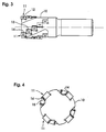
- FIG. 3 shows a side view of a milling cutter provided with inserts useful in the present invention.
- FIG. 4 shows a top view of the mill in FIG. 3.
- 10 is the milling body
- 11 is an insert
- 12 is the central hole in an insert
- 13 is the side surface of an insert
- 14 is the clearance face of an insert
- 15 is the edge surface of an insert 11.
- FIGS. 1A, 1B, 2A and 2B where the material is present in form of a plane plate 1, a laminate composed of a number of lamellas containing continuous fiber reinforcements, whereby the lamellas are piled on top of each other.
- the fibers lie oriented in planes parallel to the plane of the laminate, whereby the fiber directions are 0°, 90°, 45° and -45°.
- An opening 2 in the laminate is shaped first by, for example, drilling. Damages and/or other defects 6 frequently arise at the edge of the opening.
- a rotationally symmetrical milling body 3 is placed in the preformed hole 2.
- the laminate is oriented in such a way that the axis of rotation of the milling body 5 is perpendicular to the longitudinal direction of the fibers in the plate 1, i.e., perpendicular to the plane of the laminate.
- the opening 2 is machined by the milling body 3 partly rotating around its own axis 5 and partly by performing a translational movement relative to the edge of the opening 2 so that the damage and other defects 6 resulting from the shaping of the opening 2 are removed.
- the size and/or form of the finished opening 7 differs substantially from that of the preformed hole 2. While the finished opening can have any desired shape and size, machining with the milling body is conducted to at least remove the damage or other defects 6.
- the milling body is suitably a so called milling cutter in high speed steel, solid cemented carbide or with brazed or indexable inserts of cemented carbide, titanium-based carbonitride alloy (so-called cermet) or ceramics. Such inserts are well-known in the art and inserts of these types can be used.
- the milling cutter (if high speed steel or cemented carbide) or the inserts are preferably coated with at least one thin layer of wear resistant material such as TiC, TiN and/or Al 2 O 3 applied by the known CVD- and PVD-methods as known in the art.
- a thin layer of diamond is a particularly suitable coating.
- the total thickness of the coated layer is 20 ⁇ m, preferably 2-10 ⁇ m.
- the milling cutter contains one or more diamond bodies or said inserts are diamond impregnated.
- drilling mill whereby the whole operation can be performed with only one tool.
- a milling cutter with the design shown in Figs. 3 and 4 is particularly suitable.
- This milling cutter is a milling body 10 equipped with removable inserts 11.
- the inserts 11 can be provided with a central hole 12 through the insert, wherein a threaded locking pin (not shown) is inserted to clamp the insert 11.
- the milling cutter rotates counterclockwise in Fig. 4 whereby the side surface 13 of the insert 11 forms the clearance face of the cutting edge 14 and the edge surface 15 forms the edge of the insert chip face.
- a number of inserts 11 in the shown embodiment are arranged in a spiral path in the longitudinal direction of the milling body 10. Four such spiral paths are uniformly distributed around the circumference of the milling body 10.
Landscapes
- Engineering & Computer Science (AREA)
- Mechanical Engineering (AREA)
- Milling Processes (AREA)
Claims (6)
- Verfahren zur Bearbeitung und Formung einer Durchgangsöffnung in einem faserverstärkten Verbundwerkstoff (1) ausgehend von einem vorgeformten Loch (2), indem man einen darin angeordneten rotationssymmetrischen Werkzeugkörper (3) mit wesentlich kleinerem Durchmesser als jener des vorgeformten Loches (2) verwendet und die Öffnung (2) durch diesen Körper (3) bearbeitet und formt, der teils um seine eigene Achse (5) rotiert und teils eine Translationsbewegung in Bezug auf die Kante der Öffnung durchführt, wobei das faserverstärkte Material (1) derart ausgerichtet ist, daß die Rotationsachse des Körpers (5) im wesentlichen senkrecht zu der Längsrichtung der Fasern an der Kante der Öffnung (2) ist und die Größe und/oder Geometrie der fertigen Öffnung sich wesentlich von denen des vorgeformten Loches unterscheiden, wodurch die radiale Ausdehnung der Verletzungen und/oder Fehler (6), die aus der Vorformung des Loches (2) stammen, eine untere Grenze für die Menge von entferntem Material definiert, wobei der rotationssymmetrische Werkzeugkörper ein Fräswerkzeugkörper ist, der mit Schneidkanten versehen ist, welche in Längsrichtung des Fräswerkzeugkörpers spiralförmig angeordnet sind.
- Verfahren nach Anspruch 1, dadurch gekennzeichnet, daß der Fräswerkzeugkörper (3) mit Einsätzen (11) aus Sinterkarbid ausgestattet ist.
- Verfahren nach einem der Ansprüche 1 oder 2, dadurch gekennzeichnet, daß der Fräswerkzeugkörper (3) mit Einsätzen (11) aus Keramik ausgestattet ist.
- Verfahren nach einem der vorausgehenden Ansprüche, dadurch gekennzeichnet, daß die Einsätze (11) mit wenigstens einer dünnen Schicht von verschleißbeständigem Material überzogen sind.
- Verfahren nach dem vorausgehenden Anspruch, dadurch gekennzeichnet, daß die Einsätze mit wenigstens einer dünnen Diamantenschicht überzogen sind.
- Verfahren nach Anspruch 2, dadurch gekennzeichnet, daß die Einsätze als Wendeschneidplatten (11) gestaltet sind.
Priority Applications (1)
| Application Number | Priority Date | Filing Date | Title |
|---|---|---|---|
| EP95102817A EP0661124B1 (de) | 1992-09-15 | 1993-05-19 | Verfahren zum Bearbeiten von Verbundwerkstoffen |
Applications Claiming Priority (3)
| Application Number | Priority Date | Filing Date | Title |
|---|---|---|---|
| SE9201520A SE9201520D0 (sv) | 1992-05-14 | 1992-05-14 | Pulserande bromsljus |
| SE9202658A SE507954C2 (sv) | 1992-09-15 | 1992-09-15 | Metod att bearbeta kompositer |
| SE9202658 | 1992-09-15 |
Related Child Applications (2)
| Application Number | Title | Priority Date | Filing Date |
|---|---|---|---|
| EP95102817A Division EP0661124B1 (de) | 1992-09-15 | 1993-05-19 | Verfahren zum Bearbeiten von Verbundwerkstoffen |
| EP95102817.4 Division-Into | 1995-02-28 |
Publications (3)
| Publication Number | Publication Date |
|---|---|
| EP0571352A2 EP0571352A2 (de) | 1993-11-24 |
| EP0571352A3 EP0571352A3 (de) | 1994-03-16 |
| EP0571352B1 true EP0571352B1 (de) | 1997-10-01 |
Family
ID=26661418
Family Applications (1)
| Application Number | Title | Priority Date | Filing Date |
|---|---|---|---|
| EP19930850111 Expired - Lifetime EP0571352B1 (de) | 1992-05-14 | 1993-05-19 | Verfahren zum Bearbeiten von Verbundwerkstoffen |
Country Status (1)
| Country | Link |
|---|---|
| EP (1) | EP0571352B1 (de) |
Families Citing this family (10)
| Publication number | Priority date | Publication date | Assignee | Title |
|---|---|---|---|---|
| US6382890B1 (en) | 1999-09-01 | 2002-05-07 | Novator Ab | Hand tool apparatus for orbital drilling |
| US6719505B2 (en) | 1999-09-01 | 2004-04-13 | Novator Ab | Orbital hand tool apparatus for drilling |
| WO2008146462A1 (ja) | 2007-05-18 | 2008-12-04 | Hamamatsu Foundation For Science And Technology Promotion | 穴あけ加工装置及び穴あけ加工物の製造方法 |
| CN103551798B (zh) * | 2013-11-14 | 2016-06-29 | 北方工业大学 | 一种改善高体份金属基复合材料加工表面完整性的方法 |
| CN108025450B (zh) | 2015-09-02 | 2018-12-07 | 三菱瓦斯化学株式会社 | 钻孔用盖板、和使用其的钻孔加工方法 |
| CN108290229B (zh) * | 2015-11-26 | 2022-06-28 | 三菱瓦斯化学株式会社 | 纤维增强复合材料的切削加工方法 |
| SG11201802212QA (en) | 2016-02-17 | 2018-04-27 | Mitsubishi Gas Chemical Co | Cutting work method and method for producing cut product |
| EP3539697B1 (de) | 2016-11-14 | 2024-12-18 | Mitsubishi Gas Chemical Company, Inc. | Werkstoff zur formung einer aufgebauten kante und verfahren zur formung einer aufgebauten kante |
| EP3633014B1 (de) | 2017-05-25 | 2026-01-07 | Mitsubishi Gas Chemical Company, Inc. | Schneidarbeitsunterstützendes schmiermaterial, schneidarbeitsunterstützende schmierblatt und schneidverfahren |
| CN112223034B (zh) * | 2020-10-26 | 2022-01-07 | 宜兴留森模具制造有限公司 | 一种模具打磨抛光装置 |
Family Cites Families (3)
| Publication number | Priority date | Publication date | Assignee | Title |
|---|---|---|---|---|
| DD96861A1 (de) * | 1972-05-04 | 1973-04-12 | ||
| DE3314049A1 (de) * | 1983-04-19 | 1984-10-25 | Montanwerke Walter GmbH, 7400 Tübingen | Wendeschneidplattenbestueckter schaftfraeser |
| DE3508520A1 (de) * | 1985-03-09 | 1986-09-11 | Aichele Werkzeuge GmbH & Co KG, 7180 Crailsheim | Fraeser zum zerspanenden bearbeiten von werkstuecken |
-
1993
- 1993-05-19 EP EP19930850111 patent/EP0571352B1/de not_active Expired - Lifetime
Also Published As
| Publication number | Publication date |
|---|---|
| EP0571352A3 (de) | 1994-03-16 |
| EP0571352A2 (de) | 1993-11-24 |
Similar Documents
| Publication | Publication Date | Title |
|---|---|---|
| US5934847A (en) | Method of machining composites | |
| EP2473304B1 (de) | Drehschneidewerkzeug mit einer aus gehärtetem pcd geformten schneidekante | |
| EP0313534B1 (de) | Verfahren zur spanabhebenden Bearbeitung | |
| EP0674562B1 (de) | Methode und werkzeug zum herstellen von löchern in fiberverstärkten kompositen durch exzentrische bewegung des werkzeugs | |
| EP1137511A1 (de) | Schneideinsatz mit verbesserter kantenoberflächenrauhigkeit und verfahren zum herstellen desselben | |
| CN115397592B (zh) | 具有相交以形成四边形面部部分的连续的主退屑槽和不连续的辅助退屑槽的旋转切削刀具 | |
| López de Lacalle et al. | Advanced cutting tools | |
| Koenig et al. | Developments in drilling and contouring composites containing kevlar | |
| JPH08507724A (ja) | エンドミル | |
| EP0571352A2 (de) | Verfahren zum Bearbeiten von Verbundwerkstoffen | |
| CN1103258C (zh) | 车削旋转金属工件的方法 | |
| CA3201525A1 (en) | Cutting tool for machining fiber composite materials | |
| Santhanakrishnan et al. | High speed steel tool wear studies in machining of glass-fibre-reinforced plastics | |
| EP1803514A2 (de) | Schneidewerkzeugeinsatz | |
| US6629806B1 (en) | Process for metal-removing machining | |
| US6152660A (en) | Drilling tool for bores in solid material | |
| JP7045460B2 (ja) | 切削工具及び切削加工物の製造方法 | |
| EP4194127A1 (de) | Verfahren zur herstellung eines bohrwerkzeugschneidteils und ein solches bohrwerkzeugschneidteil | |
| JP3662773B2 (ja) | ねじ切り工具及びねじ切り方法 | |
| JPH0253511A (ja) | エンドミル | |
| JP2023505342A (ja) | 切削具とその使用方法 | |
| JP2001341026A (ja) | ボールエンドミル | |
| CN222448405U (zh) | 铣削工具 | |
| Koshy et al. | A composite tool for ball endmilling | |
| Gómez-Escudero et al. | Free-form tools design and fabrication for flank super abrasive machining (FSAM) non developable surfaces |
Legal Events
| Date | Code | Title | Description |
|---|---|---|---|
| PUAI | Public reference made under article 153(3) epc to a published international application that has entered the european phase |
Free format text: ORIGINAL CODE: 0009012 |
|
| AK | Designated contracting states |
Kind code of ref document: A2 Designated state(s): DE FR GB IT NL SE |
|
| PUAL | Search report despatched |
Free format text: ORIGINAL CODE: 0009013 |
|
| AK | Designated contracting states |
Kind code of ref document: A3 Designated state(s): DE FR GB IT NL SE |
|
| 17P | Request for examination filed |
Effective date: 19940413 |
|
| 17Q | First examination report despatched |
Effective date: 19960102 |
|
| GRAG | Despatch of communication of intention to grant |
Free format text: ORIGINAL CODE: EPIDOS AGRA |
|
| GRAH | Despatch of communication of intention to grant a patent |
Free format text: ORIGINAL CODE: EPIDOS IGRA |
|
| GRAH | Despatch of communication of intention to grant a patent |
Free format text: ORIGINAL CODE: EPIDOS IGRA |
|
| GRAA | (expected) grant |
Free format text: ORIGINAL CODE: 0009210 |
|
| AK | Designated contracting states |
Kind code of ref document: B1 Designated state(s): DE FR GB IT NL SE |
|
| DX | Miscellaneous (deleted) | ||
| PG25 | Lapsed in a contracting state [announced via postgrant information from national office to epo] |
Ref country code: NL Free format text: LAPSE BECAUSE OF FAILURE TO SUBMIT A TRANSLATION OF THE DESCRIPTION OR TO PAY THE FEE WITHIN THE PRESCRIBED TIME-LIMIT Effective date: 19971001 Ref country code: IT Free format text: LAPSE BECAUSE OF FAILURE TO SUBMIT A TRANSLATION OF THE DESCRIPTION OR TO PAY THE FEE WITHIN THE PRESCRIBED TIME-LIMIT;WARNING: LAPSES OF ITALIAN PATENTS WITH EFFECTIVE DATE BEFORE 2007 MAY HAVE OCCURRED AT ANY TIME BEFORE 2007. THE CORRECT EFFECTIVE DATE MAY BE DIFFERENT FROM THE ONE RECORDED. Effective date: 19971001 |
|
| REF | Corresponds to: |
Ref document number: 69314227 Country of ref document: DE Date of ref document: 19971106 |
|
| ET | Fr: translation filed | ||
| NLV1 | Nl: lapsed or annulled due to failure to fulfill the requirements of art. 29p and 29m of the patents act | ||
| PLBQ | Unpublished change to opponent data |
Free format text: ORIGINAL CODE: EPIDOS OPPO |
|
| PLBI | Opposition filed |
Free format text: ORIGINAL CODE: 0009260 |
|
| PLBF | Reply of patent proprietor to notice(s) of opposition |
Free format text: ORIGINAL CODE: EPIDOS OBSO |
|
| 26 | Opposition filed |
Opponent name: NOVATOR AB Effective date: 19980626 |
|
| PLBF | Reply of patent proprietor to notice(s) of opposition |
Free format text: ORIGINAL CODE: EPIDOS OBSO |
|
| PLBO | Opposition rejected |
Free format text: ORIGINAL CODE: EPIDOS REJO |
|
| PLBN | Opposition rejected |
Free format text: ORIGINAL CODE: 0009273 |
|
| STAA | Information on the status of an ep patent application or granted ep patent |
Free format text: STATUS: OPPOSITION REJECTED |
|
| 27O | Opposition rejected |
Effective date: 19991023 |
|
| REG | Reference to a national code |
Ref country code: GB Ref legal event code: IF02 |
|
| REG | Reference to a national code |
Ref country code: GB Ref legal event code: 732E |
|
| REG | Reference to a national code |
Ref country code: GB Ref legal event code: 732E |
|
| REG | Reference to a national code |
Ref country code: FR Ref legal event code: TP |
|
| REG | Reference to a national code |
Ref country code: FR Ref legal event code: TP |
|
| PGFP | Annual fee paid to national office [announced via postgrant information from national office to epo] |
Ref country code: FR Payment date: 20100525 Year of fee payment: 18 |
|
| REG | Reference to a national code |
Ref country code: FR Ref legal event code: ST Effective date: 20120131 |
|
| PG25 | Lapsed in a contracting state [announced via postgrant information from national office to epo] |
Ref country code: FR Free format text: LAPSE BECAUSE OF NON-PAYMENT OF DUE FEES Effective date: 20110531 |
|
| PGFP | Annual fee paid to national office [announced via postgrant information from national office to epo] |
Ref country code: DE Payment date: 20120516 Year of fee payment: 20 |
|
| PGFP | Annual fee paid to national office [announced via postgrant information from national office to epo] |
Ref country code: SE Payment date: 20120511 Year of fee payment: 20 Ref country code: GB Payment date: 20120516 Year of fee payment: 20 |
|
| REG | Reference to a national code |
Ref country code: DE Ref legal event code: R071 Ref document number: 69314227 Country of ref document: DE |
|
| REG | Reference to a national code |
Ref country code: GB Ref legal event code: PE20 Expiry date: 20130518 |
|
| PG25 | Lapsed in a contracting state [announced via postgrant information from national office to epo] |
Ref country code: GB Free format text: LAPSE BECAUSE OF EXPIRATION OF PROTECTION Effective date: 20130518 Ref country code: DE Free format text: LAPSE BECAUSE OF EXPIRATION OF PROTECTION Effective date: 20130522 |