EP0571484B1 - Adaptateur de recipient pour un solvant de nettoyage - Google Patents
Adaptateur de recipient pour un solvant de nettoyage Download PDFInfo
- Publication number
- EP0571484B1 EP0571484B1 EP92905150A EP92905150A EP0571484B1 EP 0571484 B1 EP0571484 B1 EP 0571484B1 EP 92905150 A EP92905150 A EP 92905150A EP 92905150 A EP92905150 A EP 92905150A EP 0571484 B1 EP0571484 B1 EP 0571484B1
- Authority
- EP
- European Patent Office
- Prior art keywords
- container
- fuel
- solvent
- fuel system
- outlet port
- Prior art date
- Legal status (The legal status is an assumption and is not a legal conclusion. Google has not performed a legal analysis and makes no representation as to the accuracy of the status listed.)
- Expired - Lifetime
Links
- 239000002904 solvent Substances 0.000 title claims abstract description 30
- 238000004140 cleaning Methods 0.000 title claims abstract description 11
- 239000000446 fuel Substances 0.000 claims abstract description 72
- 239000002828 fuel tank Substances 0.000 claims description 10
- 238000000034 method Methods 0.000 claims description 10
- 239000007788 liquid Substances 0.000 claims description 5
- 230000001105 regulatory effect Effects 0.000 claims 5
- 230000000007 visual effect Effects 0.000 claims 3
- 230000001276 controlling effect Effects 0.000 claims 1
- 238000005086 pumping Methods 0.000 claims 1
- 238000002347 injection Methods 0.000 abstract description 4
- 239000007924 injection Substances 0.000 abstract description 4
- 238000010586 diagram Methods 0.000 description 2
- 239000012535 impurity Substances 0.000 description 2
- 239000011343 solid material Substances 0.000 description 2
- OKTJSMMVPCPJKN-UHFFFAOYSA-N Carbon Chemical compound [C] OKTJSMMVPCPJKN-UHFFFAOYSA-N 0.000 description 1
- 230000015572 biosynthetic process Effects 0.000 description 1
- 229910052799 carbon Inorganic materials 0.000 description 1
- 238000002485 combustion reaction Methods 0.000 description 1
- 230000006835 compression Effects 0.000 description 1
- 238000007906 compression Methods 0.000 description 1
- 238000004090 dissolution Methods 0.000 description 1
- 238000003780 insertion Methods 0.000 description 1
- 230000037431 insertion Effects 0.000 description 1
- 239000002184 metal Substances 0.000 description 1
- 239000007787 solid Substances 0.000 description 1
- XLYOFNOQVPJJNP-UHFFFAOYSA-N water Substances O XLYOFNOQVPJJNP-UHFFFAOYSA-N 0.000 description 1
Images

Classifications
-
- F—MECHANICAL ENGINEERING; LIGHTING; HEATING; WEAPONS; BLASTING
- F02—COMBUSTION ENGINES; HOT-GAS OR COMBUSTION-PRODUCT ENGINE PLANTS
- F02M—SUPPLYING COMBUSTION ENGINES IN GENERAL WITH COMBUSTIBLE MIXTURES OR CONSTITUENTS THEREOF
- F02M65/00—Testing fuel-injection apparatus, e.g. testing injection timing ; Cleaning of fuel-injection apparatus
- F02M65/007—Cleaning
Definitions
- the present invention relates to fuel injection service units, and in particular, to a unit which is used to clean the fuel system of a motor vehicle.
- Another method of cleaning the fuel system of a fuel injected motor vehicle would be physically to remove the fuel injectors and fuel system from the motor vehicle and clean the individual parts. This requires the costly and time-consuming dismantling of the fuel pump and injectors and is therefore not a cost effective proposition.
- the apparatus of the present invention is characterised by the features of claim 1.
- the method of the present invention is characterised by the features of claim 5.
- Claims 1 and 5 are delimited over US-A-2281695 which discloses a system for degumming the cylinder walls and piston surfaces by removing the spark plug from the cylinder and connecting the spark plug orifice to a container of a solvent for the gum formation in the cylinder, with a non-return valve to ensure that while the piston descends and induces a flow of the solvent into the cylinder the non-return valve is open, but then as the piston leaves bottom dead centre on its compression stroke the non-return valve closes and the solvent already in the cylinder then becomes compressed to speed up the degree of dissolution of the gum.
- US-A-2281695 discloses a system for degumming the cylinder walls and piston surfaces by removing the spark plug from the cylinder and connecting the spark plug orifice to a container of a solvent for the gum formation in the cylinder, with a non-return valve to ensure that while the piston descends and induces a flow of the solvent into the cylinder the non-return valve is open, but then as the piston leaves
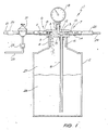
- the apparatus 1 includes a container 2 which is screw fitted to an adaptor body 3.
- the adaptor body 3 has a female thread 4 which is compatible with a reciprocal male thread 5 on the container 2.
- the adaptor body 3 therefore fits on the top of the container 2.
- the adaptor body 3 is a solid piece of metal and has an inlet port 6 and an outlet port 7 drilled and tapped therein.
- the inlet port 6 comprises a horizontal portion 8 and a vertical portion 9.
- the horizontal portion 8 is the portion which is tapped and has a screwed connector 10 which fits thereto.
- the connector 10 has a quick snap-on bayonet fitting 11 on the outside of the adaptor body 3.
- the vertical portion 9 of the inlet port 6 communicates with the interior of the container 2 when the adaptor body 3 is screwed thereon.
- the inlet port 6 has its opening adjacent the top of the container 2.
- the outlet port 7 has a horizontal portion 12 which is tapped and has a screwed connector 13 onto which a similar bayonet fitting 14 is attached on the outside of the adaptor body 3.
- the outlet port 7 has one vertical portion 15 which connects to an extension pipe 16 which has an opening adjacent the bottom of the container 2. This means that the contents of the container 2 adjacent its bottom is what exits from the container 2 via the outlet port 7 during use.
- the outlet port 7 has a second vertical portion 17 which is tapped and into which a pressure gauge 18 is screwed.
- the pressure gauge 18 is used to indicate the pressure in the outlet port 7.
- the apparatus 1 is connected into the fuel line 21, 24 of a motor vehicle (not illustrated).
- the apparatus 1 further includes a pressure regulator 19 which is snapped onto the bayonet fitting 11 of the inlet port 6.
- the pressure regulator 19 has a bayonet fitting 20 to which the fuel pressure line 21 from the fuel tank and fuel pump (not illustrated) is connected.
- the pressure regulator 19 is also connected via a flow restrictor valve 22 to a temporary return line 23 which returns fuel to the fuel tank (not illustrated).
- Connected to the outlet port 7 of the adaptor body 3 is the fuel line 24 of the motor vehicle via a visible in line flow rate meter 25 which is used to monitor the rate of flow and is able to detect colour changes in the flow of liquid in the fuel line 24.
- the fuel line 24 is connected to the engine (not illustrated).
- the apparatus 1 is temporarily connected by a motor mechanic into the fuel pressure supply line of a fuel injected motor vehicle in the engine bay, directly before the motor vehicle fuel filter or directly after the motor vehicle fuel filter but always before the fuel injector rail by means of the bayonet fittings 20 and 14.
- the temporary return line 23 is fitted prior to the connection of the container 2 and is temporarily returned to the motor vehicle's fuel tank.
- the container 2 which contains a cleaning solvent 26 is screwed tightly to the adaptor body 3 and the apparatus 1 is ready for use.
- the return line (not illustrated) of the motor vehicle is cleaned by restricting the temporary return line 23 of the apparatus 1 and by operating the vehicle fuel pump (not illustrated) either by a jumper lead or by switching the vehicle ignition on and off without starting the engine.
- the solvent 26 will be forced out of the container into the fuel line 24 and through the motor vehicle's own pressure regulator back to the tank achieving the cleansing of the motor vehicle's return line to the injector rail, the injector rail itself, the motor vehicle's pressure regulator and the motor vehicle's return line.
- the engine is not operating the solvent 26 is not forced into the fuel injectors of the motor vehicle.
- the liquid within the fuel line 24 changes when the solvent 26 in the container 2 has been used as the solvent 26 is a different colour to that of fuel 27.
- the colour change occurs as the fuel 27 is pumped via the vehicle fuel pump through the pressure line 21, the pressure regulator 19 into the inlet port 6.
- the fuel enters the container 2 at the top, and as the fuel has a density less than the solvent the fuel remains on top of the solvent within the container 2.
- the solvent 26 within the container 2 is forced through the extension pipe 16 and out of the container 2 via the outlet port 7 and through the fuel line 24 via the visible flow rate meter 25. Because the solvent 26 is coloured differently from the fuel 27, the complete removal of the solvent from the container 2 is easily observed.
- the temporary return line 23 is opened and the motor vehicle's own pressure regulator (not illustrated) stops the return flow from the apparatus 1 to the fuel tank of the motor vehicle.
- the motor mechanic starts the engine of the motor vehicle, and fuel pressure is applied from the motor vehicle's own fuel pump to the apparatus 1.
- the pressure within the fuel system can be adjusted as required by the flow restrictor valve 22 of the temporary return line 23.
- the fuel pressure is able to be monitored by the pressure gauge 18 at the same time as the solvent 26 flowing in the visible flow rate meter 25 is observed.
- the mechanic is able to ensure by using the correct pressure that the solvent 26 will flow through the fuel injectors of the motor vehicle rather than pass through the motor vehicle's pressure regulator.
- the solvent 26 is used to clean the fuel injectors together with the vehicle's fuel lines. Once the solvent 26 within the container 2 has been used, the mechanic can stop the motor vehicle's engine and remove the apparatus as the cleaning operation is completed.
- the apparatus 30 includes the container 2, and adaptor body 3 as previously described.
- the adaptor body 3 includes the inlet port 6 and outlet port 7 as previously described.
- a pressure gauge 32 is connected to the horizontal portion 12 of the outlet port 7 while a visible through flow meter 33 is screw connected into the vertical portion 17 of the outlet port 7.
- the inlet port is connected as previously described in the first embodiment with the fuel line 21 and pressure regulator 19 connected thereto.
- the apparatus 2 is able to be used in a similar manner to the previously described embodiment, and can also be used to check other operations of the fuel injection system.
Landscapes
- Engineering & Computer Science (AREA)
- Chemical & Material Sciences (AREA)
- Combustion & Propulsion (AREA)
- Mechanical Engineering (AREA)
- General Engineering & Computer Science (AREA)
- Fuel-Injection Apparatus (AREA)
- Cleaning In General (AREA)
- Cleaning By Liquid Or Steam (AREA)
- Electrical Discharge Machining, Electrochemical Machining, And Combined Machining (AREA)
- Thermally Insulated Containers For Foods (AREA)
- Detergent Compositions (AREA)
- Photographic Developing Apparatuses (AREA)
Claims (6)
- Appareil (1) de nettoyage d'un circuit de carburant, comprenant un corps (3) raccordé à la partie supérieure d'un récipient (2), le corps ayant un orifice d'entrée (6) et un orifice de sortie (7) communiquant avec l'intérieur du récipient (2), l'orifice d'entrée (6) ayant une ouverture (8, 9) débouchant dans le récipient (2) près de la partie supérieure du récipient (2) et l'orifice de sortie (7) étant raccordé à un tube (16) qui pénètre dans le récipient (2) et a une ouverture adjacente au fond du récipient, caractérisé en ce que l'appareil (1) comporte en outre un dispositif (19) de régulation de pression raccordé à l'orifice d'entrée (6) et une canalisation de retour (23) qui est aussi raccordée au dispositif (19) de régulation de pression, l'appareil étant destiné à être raccordé à une canalisation (21, 24) de carburant d'un véhicule à moteur de manière que l'orifice d'entrée (6) soit raccordé du côté du réservoir de carburant par l'intermédiaire du dispositif (19) de régulation de pression et que l'orifice de sortie (7) soit raccordé du côté du moteur, et en ce que la canalisation de retour (23) comporte un organe (22) de réduction de débit qui réduit la canalisation de retour (23) et permet ainsi le réglage de la pression dans l'appareil (1) de manière qu'un liquide (26) de nettoyage présent dans le récipient (2) soit chassé dans le circuit de carburant par fonctionnement de la pompe de carburant du véhicule et que le circuit de carburant soit nettoyé.
- Appareil selon la revendication 1, dans lequel un manomètre (18) est raccordé à l'orifice de sortie (7) pour le contrôle de la pression du liquide (26) dans l'appareil (1).
- Appareil selon la revendication 1, dans lequel un dispositif (25) d'indication visuelle de débit est raccordé à l'orifice de sortie (7) afin qu'il donne une indication visuelle du liquide (26) circulant dans l'appareil (1).
- Appareil selon la revendication 3, dans lequel le dispositif d'indication visuelle de débit (26) comporte aussi un dispositif destiné à donner une lecture de débit.
- Procédé de nettoyage d'un circuit de carburant d'un véhicule à moteur par utilisation d'un appareil (1) comprenant un corps (3) qui peut être raccordé à la partie supérieure d'un récipient (2), le corps (3) ayant un orifice d'entrée (6) et un orifice de sortie (7) communiquant avec l'intérieur du récipient (2), l'orifice d'entrée (6) ayant une ouverture (8, 9) débouchant dans le récipient (2) près de la partie supérieure du récipient (2), et l'orifice de sortie (7) étant raccordé à un tube (16) qui pénètre dans le récipient (2) et a une ouverture adjacente au fond du récipient (2), le procédé étant caractérisé par les étapes suivantes :l'installation de l'appareil (1) dans le circuit de carburant de manière que l'orifice d'entrée (6) soit raccordé au circuit de carburant par l'intermédiaire d'un dispositif (19) de régulation de pression placé du côté du réservoir de carburant, la sortie (17) soit raccordée au circuit de carburant du côté du moteur, et une canalisation de retour (23) comprenant un organe (22) de réduction de débit soit raccordée au dispositif (19) de régulation de pression et au réservoir de carburant,le raccordement d'un récipient (2) contenant un premier solvant (26) au corps (3),la fermeture de la canalisation de retour (23) par l'organe (22) de réduction de débit, etla commande de la pompe de carburant du véhicule sans fonctionnement du moteur de manière que le premier solvant (26) soit pompé dans le circuit de carburant par fonctionnement uniquement de la pompe de carburant du véhicule, le solvant passant en dérivation par rapport aux injecteurs du circuit de carburant parce que la canalisation (23) de retour est fermée, et revenant vers le réservoir de carburant.
- Procédé selon la revendication 5, comprenant en outre les étapes suivantes :le raccordement du récipient (2) contenant un second solvant,le pompage du second solvant (26) dans le circuit de carburant par fonctionnement du moteur du véhicule, etle réglage de la pression du second solvant (26) dans le circuit de carburant par ajustement de l'organe (22) de réduction de débit de manière que le second solvant (26) passe uniquement dans les injecteurs de carburant.
Applications Claiming Priority (3)
| Application Number | Priority Date | Filing Date | Title |
|---|---|---|---|
| AUPK461091 | 1991-02-14 | ||
| AU4610/91 | 1991-02-14 | ||
| PCT/AU1992/000056 WO1992014916A1 (fr) | 1991-02-14 | 1992-02-14 | Adaptateur de recipient pour un solvant de nettoyage |
Publications (3)
| Publication Number | Publication Date |
|---|---|
| EP0571484A1 EP0571484A1 (fr) | 1993-12-01 |
| EP0571484A4 EP0571484A4 (fr) | 1994-01-19 |
| EP0571484B1 true EP0571484B1 (fr) | 1996-07-24 |
Family
ID=3775227
Family Applications (1)
| Application Number | Title | Priority Date | Filing Date |
|---|---|---|---|
| EP92905150A Expired - Lifetime EP0571484B1 (fr) | 1991-02-14 | 1992-02-14 | Adaptateur de recipient pour un solvant de nettoyage |
Country Status (6)
| Country | Link |
|---|---|
| US (1) | US5516370A (fr) |
| EP (1) | EP0571484B1 (fr) |
| AT (1) | ATE140766T1 (fr) |
| CA (1) | CA2104213A1 (fr) |
| DE (1) | DE69212463T2 (fr) |
| WO (1) | WO1992014916A1 (fr) |
Families Citing this family (14)
| Publication number | Priority date | Publication date | Assignee | Title |
|---|---|---|---|---|
| US5503683A (en) * | 1994-06-27 | 1996-04-02 | Ad/Vantage Inc. | Fuel system cleaning apparatus |
| WO1997026093A1 (fr) * | 1994-06-27 | 1997-07-24 | Ad/Vantage, Inc. | Dispositif de nettoyage pour systeme de combustion |
| US6281020B1 (en) * | 1996-06-17 | 2001-08-28 | Usui Kokusai Sangyo Kaisha Limited | Method of testing cleanness of inner surfaces of the parts of a fuel injection system |
| US6000413A (en) * | 1998-09-01 | 1999-12-14 | Innova Electronics Corporation | Fuel injector cleaning system |
| US6530392B2 (en) | 2000-07-17 | 2003-03-11 | Finger Lakes Chemicals, Inc. | Valve cleaning assembly |
| US6584993B1 (en) * | 2000-11-06 | 2003-07-01 | Yen-Hsi Chang | Portable-type cleaning device for internal combustion engine |
| US6820627B1 (en) * | 2002-02-22 | 2004-11-23 | Nelson Cordova | Direct fuel injector cleaner injection device |
| US6669239B1 (en) * | 2002-05-08 | 2003-12-30 | Brunswick Corporation | Sealing device for a conduit passing through a wall |
| US20040140369A1 (en) * | 2003-01-21 | 2004-07-22 | Po-Lin Liao | Cleaning device for fuel-injection-nozzle |
| US20050178413A1 (en) * | 2004-02-13 | 2005-08-18 | Chiang Mei H. | Cleaning device for a combustion chamber |
| ITTV20050197A1 (it) * | 2005-12-16 | 2007-06-17 | Stefano Mori | Miscelatore di gas e liquido detergente per la pulizia senza smontaggio degli iniettori per gas montati su motori a ciclo otto. |
| US7774125B2 (en) * | 2008-08-06 | 2010-08-10 | Fluid Control Products, Inc. | Programmable fuel pump control |
| US9834128B2 (en) * | 2014-04-23 | 2017-12-05 | Tremcar Inc. | Tank trailer operating system |
| USD1079149S1 (en) * | 2024-05-31 | 2025-06-10 | Yi Su | Litter box |
Family Cites Families (9)
| Publication number | Priority date | Publication date | Assignee | Title |
|---|---|---|---|---|
| US1787360A (en) * | 1928-11-07 | 1930-12-30 | Frank F Cowherd | Internal-combustion-engine-cleaning device |
| US2281695A (en) * | 1939-03-21 | 1942-05-05 | Lubri Zol Corp | Gum and carbon removal |
| US4346689A (en) * | 1980-12-09 | 1982-08-31 | Neely Noah A | Controlled fuel injection system |
| JPS588259A (ja) * | 1981-07-03 | 1983-01-18 | Nissan Motor Co Ltd | 燃料噴射弁の洗浄方法及びその装置 |
| US4784170A (en) * | 1987-05-28 | 1988-11-15 | Patrick Romanelli | Fuel injector cleaner kit |
| US4807578A (en) * | 1987-09-08 | 1989-02-28 | Petro Chemical Corporation | Apparatus for cleaning fuel injectors and combustion chambers |
| GB8823693D0 (en) * | 1988-10-08 | 1988-11-16 | Hartopp R | Injector cleaning apparatus |
| US5287834A (en) * | 1991-03-08 | 1994-02-22 | Flynn Robert E | Method and apparatus for cleaning deposits and residue from internal combustion engines |
| US5257604A (en) * | 1991-05-06 | 1993-11-02 | Wynn Oil Company | Multi-mode engine cleaning fluid application apparatus and method |
-
1992
- 1992-02-14 US US08/107,671 patent/US5516370A/en not_active Expired - Fee Related
- 1992-02-14 EP EP92905150A patent/EP0571484B1/fr not_active Expired - Lifetime
- 1992-02-14 DE DE69212463T patent/DE69212463T2/de not_active Expired - Fee Related
- 1992-02-14 AT AT92905150T patent/ATE140766T1/de not_active IP Right Cessation
- 1992-02-14 WO PCT/AU1992/000056 patent/WO1992014916A1/fr not_active Ceased
- 1992-02-14 CA CA002104213A patent/CA2104213A1/fr not_active Abandoned
Also Published As
| Publication number | Publication date |
|---|---|
| ATE140766T1 (de) | 1996-08-15 |
| US5516370A (en) | 1996-05-14 |
| EP0571484A1 (fr) | 1993-12-01 |
| WO1992014916A1 (fr) | 1992-09-03 |
| DE69212463D1 (de) | 1996-08-29 |
| CA2104213A1 (fr) | 1992-08-15 |
| DE69212463T2 (de) | 1997-03-13 |
| EP0571484A4 (fr) | 1994-01-19 |
Similar Documents
| Publication | Publication Date | Title |
|---|---|---|
| EP0571484B1 (fr) | Adaptateur de recipient pour un solvant de nettoyage | |
| US4671230A (en) | Method and means for cleaning fuel injection engines | |
| US4606311A (en) | Fuel injection cleaning system and apparatus | |
| US4989561A (en) | Method and apparatus to clean the intake system of an internal combustion engine | |
| US4877043A (en) | Internal combustion engine scrubber | |
| US5503683A (en) | Fuel system cleaning apparatus | |
| US4520773A (en) | Fuel injection cleaning and testing system and apparatus | |
| AU673108B2 (en) | Apparatus for servicing automatic transmissions and the like | |
| US5097806A (en) | Multi-mode engine cleaning fluid application apparatus and method | |
| US5633457A (en) | Fuel injection cleaning and testing system and apparatus | |
| CN206221124U (zh) | 一种排查共轨喷油器高压泄露故障的工具 | |
| US8551260B2 (en) | Fuel injection flush tool | |
| CN106536894A (zh) | 一种汽车发动机喷油嘴及燃烧室除碳清洗装置及方法 | |
| WO1990001623A1 (fr) | Appareil d'entretien pour injecteurs de carburant | |
| CN108825377A (zh) | 基于图像处理的发动机自动除碳系统 | |
| EP1689998B1 (fr) | Dispositif pour transporter du carburant d'un reservoir vers un moteur a combustion interne et procede pour detecter la pression | |
| JPS58119965A (ja) | 燃料噴射バルブシステムの浄化装置 | |
| US20070243077A1 (en) | Testing Method | |
| AU653003B2 (en) | Can adaptor for cleaning solvent | |
| US7892363B2 (en) | Cleaning tool assembly and method for cleaning a fuel injector | |
| US6637468B1 (en) | High speed engine coolant flush and filtration system and method | |
| CN210948961U (zh) | 内燃机的液压供油装置及具有其的船舶 | |
| CN222526408U (zh) | 一种智能型发动机缸内积碳动态除碳设备 | |
| CN2549186Y (zh) | 引擎积碳清洗机 | |
| CN219366195U (zh) | 燃油供应装置及供油提前角调整系统 |
Legal Events
| Date | Code | Title | Description |
|---|---|---|---|
| PUAI | Public reference made under article 153(3) epc to a published international application that has entered the european phase |
Free format text: ORIGINAL CODE: 0009012 |
|
| 17P | Request for examination filed |
Effective date: 19930915 |
|
| AK | Designated contracting states |
Kind code of ref document: A1 Designated state(s): AT BE DE DK FR GB IT LU MC NL SE |
|
| A4 | Supplementary search report drawn up and despatched |
Effective date: 19931130 |
|
| AK | Designated contracting states |
Kind code of ref document: A4 Designated state(s): AT BE DE DK FR GB IT LU MC NL SE |
|
| 17Q | First examination report despatched |
Effective date: 19941013 |
|
| GRAH | Despatch of communication of intention to grant a patent |
Free format text: ORIGINAL CODE: EPIDOS IGRA |
|
| GRAH | Despatch of communication of intention to grant a patent |
Free format text: ORIGINAL CODE: EPIDOS IGRA |
|
| GRAA | (expected) grant |
Free format text: ORIGINAL CODE: 0009210 |
|
| AK | Designated contracting states |
Kind code of ref document: B1 Designated state(s): AT BE DE DK FR GB IT LU MC NL SE |
|
| PG25 | Lapsed in a contracting state [announced via postgrant information from national office to epo] |
Ref country code: DK Effective date: 19960724 Ref country code: BE Effective date: 19960724 |
|
| REF | Corresponds to: |
Ref document number: 140766 Country of ref document: AT Date of ref document: 19960815 Kind code of ref document: T |
|
| REF | Corresponds to: |
Ref document number: 69212463 Country of ref document: DE Date of ref document: 19960829 |
|
| ITF | It: translation for a ep patent filed | ||
| ET | Fr: translation filed | ||
| PG25 | Lapsed in a contracting state [announced via postgrant information from national office to epo] |
Ref country code: LU Free format text: LAPSE BECAUSE OF NON-PAYMENT OF DUE FEES Effective date: 19970228 |
|
| PLBE | No opposition filed within time limit |
Free format text: ORIGINAL CODE: 0009261 |
|
| STAA | Information on the status of an ep patent application or granted ep patent |
Free format text: STATUS: NO OPPOSITION FILED WITHIN TIME LIMIT |
|
| 26N | No opposition filed | ||
| PG25 | Lapsed in a contracting state [announced via postgrant information from national office to epo] |
Ref country code: MC Effective date: 19970831 |
|
| PGFP | Annual fee paid to national office [announced via postgrant information from national office to epo] |
Ref country code: FR Payment date: 19990215 Year of fee payment: 8 |
|
| PGFP | Annual fee paid to national office [announced via postgrant information from national office to epo] |
Ref country code: GB Payment date: 19990218 Year of fee payment: 8 |
|
| PGFP | Annual fee paid to national office [announced via postgrant information from national office to epo] |
Ref country code: NL Payment date: 19990224 Year of fee payment: 8 |
|
| PGFP | Annual fee paid to national office [announced via postgrant information from national office to epo] |
Ref country code: SE Payment date: 19990301 Year of fee payment: 8 |
|
| PG25 | Lapsed in a contracting state [announced via postgrant information from national office to epo] |
Ref country code: GB Free format text: LAPSE BECAUSE OF NON-PAYMENT OF DUE FEES Effective date: 20000214 |
|
| PG25 | Lapsed in a contracting state [announced via postgrant information from national office to epo] |
Ref country code: SE Free format text: LAPSE BECAUSE OF NON-PAYMENT OF DUE FEES Effective date: 20000215 |
|
| PGFP | Annual fee paid to national office [announced via postgrant information from national office to epo] |
Ref country code: AT Payment date: 20000225 Year of fee payment: 9 |
|
| PG25 | Lapsed in a contracting state [announced via postgrant information from national office to epo] |
Ref country code: NL Free format text: LAPSE BECAUSE OF NON-PAYMENT OF DUE FEES Effective date: 20000901 |
|
| GBPC | Gb: european patent ceased through non-payment of renewal fee |
Effective date: 20000214 |
|
| EUG | Se: european patent has lapsed |
Ref document number: 92905150.6 |
|
| PG25 | Lapsed in a contracting state [announced via postgrant information from national office to epo] |
Ref country code: FR Free format text: LAPSE BECAUSE OF NON-PAYMENT OF DUE FEES Effective date: 20001031 |
|
| NLV4 | Nl: lapsed or anulled due to non-payment of the annual fee |
Effective date: 20000901 |
|
| REG | Reference to a national code |
Ref country code: FR Ref legal event code: ST |
|
| PG25 | Lapsed in a contracting state [announced via postgrant information from national office to epo] |
Ref country code: AT Free format text: LAPSE BECAUSE OF NON-PAYMENT OF DUE FEES Effective date: 20010214 |
|
| PGFP | Annual fee paid to national office [announced via postgrant information from national office to epo] |
Ref country code: DE Payment date: 20010427 Year of fee payment: 10 |
|
| PG25 | Lapsed in a contracting state [announced via postgrant information from national office to epo] |
Ref country code: DE Free format text: LAPSE BECAUSE OF NON-PAYMENT OF DUE FEES Effective date: 20020903 |
|
| PG25 | Lapsed in a contracting state [announced via postgrant information from national office to epo] |
Ref country code: IT Free format text: LAPSE BECAUSE OF NON-PAYMENT OF DUE FEES Effective date: 20050214 |