EP0571797B1 - Einrichtung zur Stimulation des Herzens - Google Patents
Einrichtung zur Stimulation des Herzens Download PDFInfo
- Publication number
- EP0571797B1 EP0571797B1 EP93107473A EP93107473A EP0571797B1 EP 0571797 B1 EP0571797 B1 EP 0571797B1 EP 93107473 A EP93107473 A EP 93107473A EP 93107473 A EP93107473 A EP 93107473A EP 0571797 B1 EP0571797 B1 EP 0571797B1
- Authority
- EP
- European Patent Office
- Prior art keywords
- heart
- stimulation
- conductive
- electrode
- conductive surfaces
- Prior art date
- Legal status (The legal status is an assumption and is not a legal conclusion. Google has not performed a legal analysis and makes no representation as to the accuracy of the status listed.)
- Expired - Lifetime
Links
Images

Classifications
-
- A—HUMAN NECESSITIES
- A61—MEDICAL OR VETERINARY SCIENCE; HYGIENE
- A61N—ELECTROTHERAPY; MAGNETOTHERAPY; RADIATION THERAPY; ULTRASOUND THERAPY
- A61N1/00—Electrotherapy; Circuits therefor
- A61N1/02—Details
- A61N1/04—Electrodes
- A61N1/05—Electrodes for implantation or insertion into the body, e.g. heart electrode
- A61N1/056—Transvascular endocardial electrode systems
- A61N1/0565—Electrode heads
Definitions
- This invention relates to a heart stimulation apparatus for intracardial stimulation of heart tissue and/or sensing heart signals in accordance with claim 1.
- U.S. patent 4,628,934 describes a heart stimulation apparatus in which an electrode device's distal end can be provided with a plurality of independently connectable electrodes.
- An electrode device is prior art through U.S. patent 3,911,928.
- a plurality of relatively small conductive surfaces are arrayed on the head of the electrode device in order to reduce the threshold value and, thus, energy consumption. All the conductive surfaces on the head of this electrode device are connected to the same conductor. This can result in needlessly heavy energy consumption, since some of the conductive surfaces are not in contact with heart tissue for stimulation.
- U.S. patent 4,760,852 describes a pacemaker electrode whose distal end has a plurality of relatively large conductive surfaces connected to the same conductor.
- US-A-4 848 352 describes an electrode device having a plurality of electrodes which may be combined by electrical connectors to provide a larger electrode.
- the object of the invention is to achieve a heart stimulation apparatus with which an op, timal threshold value for each patient, and therefore the lowest energy consumption is always attained. Another objective is to achieve optimal sensing of heart signals.
- the stimulation surface(s) which provide(s) the lowest stimulation threshold is automatically selected.
- a stimulation pulse may be delivered unipolarly via one of the surfaces, a combination of two surfaces or three surfaces, or bipolary between two single surfaces or between a single surface and a double surface.
- the autocapture means may test all possible combinations or a selected number of combinations programmed by a physician.
- the stimulation pulses could also be displaced in time and amplitude at the different surfaces. This means that the duration of pulses could vary, but it also means that a second pulse could arrive before a preceding pulse is emitted. In this manner, a pulse can be given the exact morphology desired. Analogously, the sensing of heart signals can be made from the surface(s) providing the lowest sensing threshold.
- the conductive surface providing the lowest stimulation threshold is connected to a negative output of the stimulation pulse generator.
- Another advantageous version of the heart stimulation apparatus is achieved when the number and choice of conductive surfaces, connected via the conductor(s) to the detector for sensing, are selected independently of the conductive surface(s) employed for stimulation. This results in a large selection of sensing surfaces on the electrode head.
- the sensing surface may be selectable in such a way that it is not the same surface used for stimulation. This would be an advantage in sensing immediately after a stimulation, since the stimulating surface is then polarized, and any sensing could "drown" in the stimulation surface's polarization voltage.
- the conductive surfaces be evenly distributed over the electrode head. In this way, one or more electrode surface(s) would always be optimally placed against heart tissue.
- the electrode head be hemispherical and that the conductive surfaces be arrayed close to one another. In this manner, a relatively large number of conductive surfaces can be installed on a very small electrode head.
- the shape of the electrode head ensures that heart tissue is not damaged.
- the center of the electrode head has a projecting part with a conductive surface. Since the projecting part is extremely small, this part has at least a chance of retaining contact with heart tissue if the electrode head becomes dislocated.
- the electrode head consist of at least two conductive bodies which are insulated from one another.
- the electrode head can have a configuration in which one of the conductive bodies is displaced in relation to the other.
- the free end of the projecting body in addition to the sides of the free end, can be insulated to prevent any conduction between the conductive surfaces of the bodies.
- the conductive surfaces of one body or another, or of both bodies can be used for simultaneous stimulation of heart tissue and/or sensing of heart signals.
- the electrode head be equipped with a traumatic fixation component on which at least one conductive surface is provided. This achieves both fixation of the electrode head to the heart wall and ensures that at least two conductive surfaces are in contact with heart tissue.
- the fixation component be helical. In this way, the electrode head can be partially screwed into heart tissue.
- At least one of the conductive surfaces is made of a microporous material.
- the stimulation electrode and the indifferent electrode can be made very small while the conductive surfaces are relatively large at the same time.
- At least one of the conductive surfaces can also be coated with a layer of ion exchange material.
- the ion exchange material serves e.g. as protection against soiling particles.
- the conductive surfaces are highly sensitive to such particles, particularly when the surfaces are made from a microporous material.
- the invention can suitably be refined in an embodiment by having a coating of medication on at least one of the conductive surfaces.
- This coating has an antiinflammatory effect when the electrode head presses against or is screwed into the heart wall. In this manner, formation of fibrous tissue around the electrode head, something which otherwise could occur, is avoided or reduced.
- FIG. 1 depicts a heart stimulation apparatus 14 for intracardial stimulation of the heart tissue of a patient and/or sensing heart signals.
- the apparatus 14 comprises an electrode device 1 containing an electrode cable 2 equipped with a hemispherical electrode head 3 at its distal end.
- the electrode head 3 is fitted with four round, closely spaced conductive surfaces 4, 5, 6, 7 which are evenly distributed on the electrode head 3 and which are electrically separated by insulating material 8.
- the conductive surface 7 is hidden in this Figure 1.
- Each conductive surface 4, 5, 6, 7 is connected to its own elongate, flexible conductor 9, 10, 11, 12 extending to the proximal end of the electrode cable, the conductors 9, 10, 11, 12 insulated from one another.
- the electrode cable 2 is also provided with an external layer of insulation 13.
- the heart stimulation apparatus 14 is connected to the proximal end of the electrode cable 2.
- the heart stimulation apparatus 14 further comprises a switch 15 with four output terminals 16, 17, 18, 19, each connected to its own conductor 9, 10, 11, 12 for the conductive surfaces 4, 5, 6, 7 on the electrode head 3.
- the switch 15 also has an electronics unit 20 connected to the output terminals 16, 17, 18, 19.
- the heart stimulation apparatus 14 additionally contains a stimulation pulse generator 21 and a detector 22 for sensing, each of which individually connected to the electronics unit 20, and an autocapture function unit 23 which is connected to the stimulation pulse generator 21, to the detector 22 and to the electronics unit 20.
- FIG. 2 shows that the conductive surfaces 4, 5, 6, 7 are evenly arrayed on the electrode head 3.
- the conductive surfaces 4, 5, 6, 7 are the ends of wires made from a conductive material whose other ends are connected to one of the conductors 9, 10, 11, 12, insulated from one another, as shown in cross-section through the electrode device in FIG. 3.
- the stimulation generator 21 is switched via the electronics unit 20 , e.g. via output terminal 18 and conductor 11, to the conductive surface 6, a voltage for stimulating the heart tissue then being applied to said surface 6.
- the detector 22 is then switched in the same way, via the electronics unit 20, via one or more of the output terminals 16, 17, 18, 19 and via the corresponding conductor 9, 10, 11, 12, to one or more conductive surfaces 4, 5, 6, 7 for sensing heart signals.
- the number and selection of conductive surfaces 4, 5, 6, 7 connected to the detector 22, via one or more of the conductors 9, 10, 11, 12, can be selected independently of the conductive surface(s) 4, 5, 6, 7 employed for stimulation. All conductive surfaces 4, 5, 6, 7 can be switched with advantage to the detector 22.
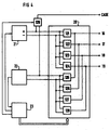
- FIG. 4 the structure in the heart stimulation apparatus 14 which executes the autocapture function and selection of electrode surface configuration is shown in a block diagram.
- the stimulation pulse generator 21, detector 22 and autocapture funciton unit 23 are, as also shown in FIG. 1, connected to the electronics unit 20.
- a first switch 121 is connected between output terminal 16 and stimulation pulse generator 21
- a second switch 122 is connected between the output terminal 17 and the stimulation pulse generator 21
- a third switch 123 is connected between output terminal 18 and the stimulation pulse generator 21
- a fourth switch 124 is connected between output terminal 19 and the stimulation pulse generator 21
- a fifth switch 125 is connected between output terminal 16 and the detector 22
- a sixth switch 126 is connected between output terminal 17 and the detector 22
- a seventh switch 127 is connected between output terminal 18 and the detector 22
- an eighth switch 128 is connected between output terminal 19 and the detector 22.
- the switches 121 - 128 can, when activated by the autocapture function unit 23, selectively connect any output terminal 16, 17, 18, 19 or combination of output terminals 16, 17, 18, 19 to the pulse generator 21 and/or detector 22 respectively. Further, a ninth switch 129 can connect neither, either or both of the stimulation pulse generator 21 and detector 22 to the heart stimulation apparatus's 14 case for unipolar stimulation and sensing.
- the autocapture function unit 23 is programmed to automatically search for the conductive surface combination which results in the lowest stimulation threshold. This means that the autocapture function unit 23 will selectively, through the switches 121 to 129 test a sequence of different stimulation arrangements and select the most efficient one.
- the autocapture function in itself is known. Basically, it is performed by reducing the stimulation energy until there is no reaction from the heart, i.e. no capture, whereafter the stimulation energy is increased until a capture is detected by the detector 22 and the threshold is determined.
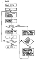
- FIG. 5 illustrates one possible flow chart for performing a selection of the ten lowest thresholds of all programmed combinations.
- the number of possible combinations could be larger than the number of programmed combinations. This because it may, for instance, not be suitable to stimulate bipolarly between two conductive surfaces which are located too closely to each other.
- the determined threshold for the actual combination will be compared with the stored thresholds and if any stored threshold is higher than the presently determined threshold (YES in block IS STORED THRESHOLD HIGHER?) the stored combination will be replaced with the present combination and threshold.
- the number of tested combinations is now incremented and the function proceeds as described above.
- this flow chart only indicates the carrying out of the autocapture function. If the number of possible combinations is large, it could be very inconvenient for a patient if the heart stimulation apparatus was to run through all combinations in uninterrupted sequence. In particular the block DETERMINE THRESHOLD could therefore include timing functions reducing the number of tests per hour or the like. When no specific combination has been selected automatically the heart will be stimulated using either a combination and stimulation energy selected by a physician or a combination and stimulation energy previously chosen by the autocapture function.
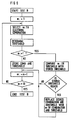
- FIG. 6 illustrates a flow chart for a TEST B.
- TEST B is a continuation of TEST A and in TEST B the stored ten combinations are tested to determine which of the ten that has the lowest threshold.
- TEST B could be routinely performed by the heart stimulation apparatus 14 to ensure that it is the combination having the lowest threshold that is permanently activated.
- the flow chart begins with a START TEST B block, which could be initiated automatically at selected time intervals by the autocapture function unit 23.
- the threshold is determined.
- TEST B it is only relevant to find the combination having the lowest threshold and the first threshold will therefore be stored to be compared with other combinations.
- the number for the combination is incremented and the function controls if all combinations have been checked yet in which case TEST B is ended. Otherwise the next combination is selected and its threshold determined.
- the present combination and its threshold is now compared with the stored combination and threshold and if the stored threshold is higher, the present combination and threshold will replace the previously stored combination and threshold and the function proceeds by incrementing the number of combinations.
- the autocapture function unit will use the selected combination until a new test may indicate that another number of combination is preferable, or when a physician by telemetry by means of an external programming unit selects a different combination for stimulation.
- the autocapture function unit may select a combination of conductive surfaces 4, 5, 6, 7 which provides the best sensing level for the detector 22.
- the autocapture function unit 23 may execute, according to the claims. Further, when connected bipolarly the autocapture function unit 23 may switch the connection so that the negative conductive surface(s) becomes positive and vice versa. The pole change may be executed automatically if an increase in the threshold is detected by the autocapture function unit 23, thereby testing which of the two combinations provides the lowest threshold.
- FIG. 7 shows a heart stimulation apparatus 224 with a function corresponding to the function shown and described in FIG. 1.
- An electrode device 225 whose design only differs from the previously illustrated and described electrode device 1 by having a different configuration for the electrode head, is connected to this heart stimulation apparatus 224.
- the electrode device 225 contains a cable 226 on whose distal end an electrode head 227 is provided.
- the electrode head 227 consists of two conductive bodies, 228, 229 which are electrically insulated from one another by a layer of insulation 230.
- the center of the body 228 is equipped with a through opening in which the body 229 is inserted.
- the bodies 228, 229 are also displaced in relation to one another so the electrode head's 227 center, as seen from the side, has a projecting part formed by the body 229, the side of the partially free end of this body having a conductive surface 231.
- the free surface of the body 228 forms a second conductive surface 232. Since the insulation 230 covers the body 229, in addition to the end side, no electrical conduction can occur between the conductive surfaces 231, 232.
- conductive surfaces 231, 232 are connected to a respective elongate, flexible, insulated conductor 233, 234 extending to the electrode cable's 226 proximal end and connected to their respective output terminal 235, 236 on a switch 237 which also contains an electronics unit 220 which functions analogously with the previously described electronics unit 20.
- the electronics unit 220 is, in turn, connected to a stimulation pulse generator 221, a detector 222 and a function unit 223 for autocapture.
- the electrode cable 226 is also provided with an external layer of insulation 238.
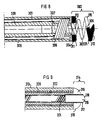
- FIG. 8 shows the distal end of a bipolar electrode device for intracardial stimulation of heart tissue in a patient.
- the electrode device contains an electrode cable 301 on whose distal end an electrode head 302 with a helical fixation device 303 is installed.
- the electrode head 302 is provided with two conductive surfaces 304,305, each connected to its own elongate conductor 306, 307 which runs inside the electrode cable 301 and extends to the proximal end of the electrode cable, said conductors 306, 307 insulated from one another by a layer of insulation 308.
- the electrode cable 301 is also provided with an external layer of insulation 309. This FIG.
- the conductive surfaces 304, 305 are made of a microporous material, such as titanium nitride. To protect these surfaces 304, 305 from soiling particles, the surfaces are coated with a layer of ion exchange material 311 which, in this embodiment, is in turn coated with a layer of medication 312 which is to exert e.g. an antiinflammatory effect when the electrode is applied.
- the conductors 306, 307 for the conductive surfaces 304, 305 can be connected in an optional manner to different poles in a pacemaker (not shown) in such a way that conductive surface 304, for example, serves as an indifferent electrode and conductive surface 305 serves as a stimulation electrode. When necessary, the conductive surface 305 can consequently serve as the indifferent electrode and the conductive surface 304 be used as the stimulation electrode.
- FIG. 9 shows a non-traumatic electrode device containing an electrode cable 313 on whose distal end an electrode head 314 is installed.
- the electrode head 314 is made up of two conductive bodies 315, 316 which are electrically insulated from one another by a layer of insulation 317.
- the center of the body 315 is provided with a through opening in which the body 316 is installed.
- the bodies 315, 316 are even displaced in relation to one another so the center of the electrode head 314, seen in profile, has a protruding part formed by the body 316, the partially free end side of this body consisting of a conductive surface 318.
- the free surface of the body 315 forms a second conductive surface 319.
- Each of the conductive surfaces 318, 319 is connected to an elongate, flexible, individually insulated conductor 320, 321 which runs to the proximal end of the electrode cable 313.
- the electrode cable 313 is also provided with an external layer of insulation 322.
- either the conductive surface 318 or the conductive surface 319 can be connected to a pacemaker in such a way that either, as described referring to FIG. 8, can serve as an indifferent electrode or as a stimulation electrode.
- Conductive surfaces 318, 319 which are made of a microporous material, can, like conductive surfaces 304, 305 in FIG. 8, be coated with an ion exchange material and with a layer of medication, even if this is not shown in this Figure 9.
- the electrode device's electrode head is not limited to the described embodiments.
- the essential thing is that the conductive surfaces on the electrode head are electrically insulated from one another so the operator has an opportunity to use one or a desired combination of several conductive surfaces for attaining optimal stimulation with minimal energy consumption.
- the number of conductive surfaces is not limited.
- the size and shape of all or some of the surfaces can vary.
Landscapes
- Health & Medical Sciences (AREA)
- Heart & Thoracic Surgery (AREA)
- Vascular Medicine (AREA)
- Cardiology (AREA)
- Engineering & Computer Science (AREA)
- Biomedical Technology (AREA)
- Nuclear Medicine, Radiotherapy & Molecular Imaging (AREA)
- Radiology & Medical Imaging (AREA)
- Life Sciences & Earth Sciences (AREA)
- Animal Behavior & Ethology (AREA)
- General Health & Medical Sciences (AREA)
- Public Health (AREA)
- Veterinary Medicine (AREA)
- Electrotherapy Devices (AREA)
Claims (17)
- Ein Herzschrittmacher zur intrakardialen Stimulation von Herzgewebe und/oder zum Abfühlen von Herzsignalen mit einer Elektrodenvorrichtung mit einem an deren distalem Ende angebrachten Elektrodenkopf, wobei der Elektrodenkopf mit einer ersten mit einem ersten Leiter (9-12, 233, 234, 306, 307, 320, 321) verbundenen leitenden Oberfläche (4-7, 231, 232, 304, 305, 318, 319) zur Stimulation des Herzgewebes und/oder dem Abfühlen der Herzsignale und mindestens einer zweiten leitenden Oberfläche (4-7, 231, 232, 304, 305, 318, 319) zur Stimulation des Herzgewebes und/oder dem Abfühlen der Herzsignale, wobei diese zweite leitende Oberfläche (4-7, 231, 232, 304, 305, 318, 319) von der ersten leitenden Oberfläche (4-7, 231, 232, 304, 305, 318, 319) isoliert und mit einem zweiten von dem ersten Leiter (9-12, 233, 234, 306, 307, 320, 321) isolierten Leiter (9-12, 233, 234, 306, 307, 320, 321) verbunden ist, einem Stimulationsimpulsgenerator (21, 221) und einem Detektor (22, 222) und einem Schalter (15, 237) zum Verbinden einer der leitenden Oberflächen (4-7, 231, 232, 304, 305, 318, 319) oder mehrere der leitenden Oberflächen (4-7, 231, 232, 304, 305, 318, 319) mit dem Stimulationsimpulsgenerator (21, 221) und/oder dem Detektor (22, 222) in jeder gewünschten Art, wobei der Schalter mit Hilfe eines Autocapuremittels derart gesteuert wird, daß die leitenden Oberflächen (4-7, 231, 232, 304, 305, 318, 319) automatisch in einer Vielzahl verschiedener Kombinationen über die Leiter (9-12, 233, 234, 306, 307, 320, 321) mit dem Stimulationsimpulsgenerator (21, 221) verbunden und deren Stimulations- und/oder Abfühlniveau getestet werden, dadurch gekennzeichnet, daß eine vorbestimmte Anzahl dieser Kombinationen, die das beste Stimulations- und/oder Abfühlniveau haben, ausgewählt werden und dann die ausgewählten Kombinationen getestet werden, um die optimale Stimulation mit minimalem Energieverbrauch und/oder einem optimalen Abfühlniveau zu erzielen.
- Ein Herzschrittmacher nach Anspruch 1, bei dem die vorbestimmte Anzahl kleiner als zehn ist.
- Ein Herzschrittmacher nach Anspruch 1, bei dem die vorbestimmte Anzahl größer als zehn ist.
- Ein Herzschrittmacher nach Anspruch 1, bei dem die vorbestimmte Anzahl zehn ist.
- Ein Herzschrittmacher nach einem der Ansprüche 1 bis 4, bei dem eine leitende Oberfläche (4-7, 231, 232, 304, 305, 318, 319) als Stimulationselektrode dient und die andere leitende Oberfläche (4-7, 231, 232, 304, 305, 318, 319) als indifferente Elektrode dient.
- Ein Herzschrittmacher nach einem der Ansprüche 1 bis 5, bei dem die leitende(n) Oberfläche(n) (4-7, 231, 232, 304, 305, 318, 319), die das niedrigste Stimulationsniveau aufweist(aufweisen), mit einem negativen Ausgang des Stimulationsimpulsgenerators (21; 221) verbunden ist(sind).
- Ein Herzschrittmacher nach einem der Ansprüche 1 bis 6, bei dem Anzahl und Auswahl der leitenden Oberflächen (4-7; 231, 232), die zum Abfühlen über den(die) Leiter (9-12; 233, 234) mit dem Detektor (22; 222) verbunden sind, unabhängig davon ausgewählt werden, ob die leitende(n) Oberfläche(n) (4-7; 231, 232) zur Stimulation eingesetzt wird(werden).
- Ein Herzschrittmacher nach einem der Ansprüche 1 bis 7, bei dem alle leitenden Oberflächen (4-7; 331, 332) zum Abfühlen mit dem Detektor (22; 222) verbunden sind.
- Ein Herzschrittmacher nach einem der Ansprüche 1 bis 8, bei dem der Elektrodenkopf (227) mindestens aus zwei leitenden Körpern (228, 229) besteht, die voneinander isoliert sind.
- Ein Herzschrittmacher nach Anspruch 9, bei dem das Zentrum des Elektrodenkopfes (227) einen hervorstehenden Teil (229) mit einer leitenden Oberfläche (231) aufweist.
- Ein Herzschrittmacher nach einem der Ansprüche 1 bis 9, bei dem der Elektrodenkopf (302) mit einer traumatischen Befestigungskomponente (303) ausgestattet ist, auf der zumindest eine leitende Oberfläche (305) vorgesehen ist.
- Ein Herzschrittmacher nach einem der Ansprüche 1 bis 11, bei dem die Befestigungskomponente (303) wendelförmig ist.
- Ein Herzschrittmacher nach einem der Ansprüche 1 bis 8, bei dem die leitenden Oberflächen (4-7; 231, 232) gleichmäßig auf dem Elektrodenkopf (3; 237) angeordnet sind.
- Ein Herzschrittmacher nach einem der Ansprüche 1 bis 8, bei dem der Elektrodenkopf (3) hemisphärisch ist und die leitenden Oberflächen (4-7) dicht aneinander angeordnet sind.
- Ein Herzschrittmacher nach einem der Ansprüche 1 bis 14, bei dem zumindest eine der leitenden Oberflächen (304, 305; 318, 319) aus mikroporösem Material besteht.
- Ein Herzschrittmacher nach einem der Ansprüche 1 bis 15, bei dem zumindest eine der leitenden Oberflächen (304, 305; 318, 319) mit einer Schicht aus einem Ionen autauschenden Material (311) beschichtet ist.
- Ein Herzschrittmacher nach einem der Ansprüche 1 bis 16, bei dem zumindest eine der leitenden Oberflächen (304, 305; 318, 319) mit einer Medikamentenschicht (312) beschichtet ist.
Applications Claiming Priority (4)
| Application Number | Priority Date | Filing Date | Title |
|---|---|---|---|
| SE9201640 | 1992-05-25 | ||
| SE9201640A SE9201640D0 (sv) | 1992-05-25 | 1992-05-25 | Elektrodanordning |
| SE9202479A SE9202479D0 (sv) | 1992-08-28 | 1992-08-28 | Elektrodanordning |
| SE9202479 | 1992-08-28 |
Publications (3)
| Publication Number | Publication Date |
|---|---|
| EP0571797A1 EP0571797A1 (de) | 1993-12-01 |
| EP0571797B1 true EP0571797B1 (de) | 1998-09-16 |
| EP0571797B2 EP0571797B2 (de) | 2005-10-26 |
Family
ID=26661431
Family Applications (1)
| Application Number | Title | Priority Date | Filing Date |
|---|---|---|---|
| EP93107473A Expired - Lifetime EP0571797B2 (de) | 1992-05-25 | 1993-05-07 | Einrichtung zur Stimulation des Herzens |
Country Status (4)
| Country | Link |
|---|---|
| US (1) | US5306292A (de) |
| EP (1) | EP0571797B2 (de) |
| JP (1) | JPH0670990A (de) |
| DE (1) | DE69321030T3 (de) |
Cited By (1)
| Publication number | Priority date | Publication date | Assignee | Title |
|---|---|---|---|---|
| US7225035B2 (en) | 2004-06-24 | 2007-05-29 | Medtronic, Inc. | Multipolar medical electrical lead |
Families Citing this family (52)
| Publication number | Priority date | Publication date | Assignee | Title |
|---|---|---|---|---|
| NL9400817A (nl) * | 1994-05-18 | 1996-01-02 | Cordis Europ | Catheter met ringelektroden en deze omvattende ablatie-inrichting. |
| SE9402775D0 (sv) * | 1994-08-19 | 1994-08-19 | Siemens Elema Ab | Elektrodanordning för intrakardiell stimulering av hjärtvävnaden och/eller avkänning av hjärtsignalerna hos en patient |
| DE69631681T2 (de) * | 1995-10-06 | 2004-07-29 | Cordis Webster, Inc., Diamond Bar | Elektroden-katheter mit geteilter spitze |
| US5755664A (en) * | 1996-07-11 | 1998-05-26 | Arch Development Corporation | Wavefront direction mapping catheter system |
| US5720775A (en) * | 1996-07-31 | 1998-02-24 | Cordis Corporation | Percutaneous atrial line ablation catheter |
| US6212434B1 (en) | 1998-07-22 | 2001-04-03 | Cardiac Pacemakers, Inc. | Single pass lead system |
| US6501994B1 (en) * | 1997-12-24 | 2002-12-31 | Cardiac Pacemakers, Inc. | High impedance electrode tip |
| US6134478A (en) * | 1998-06-05 | 2000-10-17 | Intermedics Inc. | Method for making cardiac leads with zone insulated electrodes |
| US6064905A (en) * | 1998-06-18 | 2000-05-16 | Cordis Webster, Inc. | Multi-element tip electrode mapping catheter |
| US6463334B1 (en) | 1998-11-02 | 2002-10-08 | Cardiac Pacemakers, Inc. | Extendable and retractable lead |
| US6501990B1 (en) | 1999-12-23 | 2002-12-31 | Cardiac Pacemakers, Inc. | Extendable and retractable lead having a snap-fit terminal connector |
| US6210406B1 (en) | 1998-12-03 | 2001-04-03 | Cordis Webster, Inc. | Split tip electrode catheter and signal processing RF ablation system |
| US6171275B1 (en) | 1998-12-03 | 2001-01-09 | Cordis Webster, Inc. | Irrigated split tip electrode catheter |
| DE19930265A1 (de) * | 1999-06-25 | 2000-12-28 | Biotronik Mess & Therapieg | Elektrodenanordnung |
| DE19930271A1 (de) * | 1999-06-25 | 2000-12-28 | Biotronik Mess & Therapieg | Elektrodenanordnung |
| SE0003341D0 (sv) | 2000-09-18 | 2000-09-18 | St Jude Medical | A coating method |
| US6609027B2 (en) | 2001-02-23 | 2003-08-19 | Pacesetter, Inc. | His Bundle sensing device and associated method |
| US7010350B2 (en) * | 2001-03-21 | 2006-03-07 | Kralik Michael R | Temporary biventricular pacing of heart after heart surgery |
| US6950696B2 (en) * | 2001-11-27 | 2005-09-27 | St. Jude Medical Ab | Method and circuit for detecting cardiac rhythm abnormalities by analyzing time differences between unipolar signals from a lead with a multi-electrode tip |
| US6728575B2 (en) | 2001-11-30 | 2004-04-27 | St. Jude Medical Ab | Method and circuit for detecting cardiac rhythm abnormalities using a differential signal from a lead with a multi-electrode tip |
| US6745075B2 (en) | 2001-12-20 | 2004-06-01 | St. Jude Medical Ab | Method and apparatus for detection of premature atrial contraction |
| US6745640B2 (en) * | 2002-05-15 | 2004-06-08 | Reliance Electric Technologies, Llc | Method for manufacturing a worm shaft for a gearbox and gearbox incorporating same |
| US7027852B2 (en) * | 2002-05-21 | 2006-04-11 | Pacesetter, Inc. | Lead with distal tip surface electrodes connected in parallel |
| US7738959B2 (en) | 2002-09-30 | 2010-06-15 | Medtronic, Inc. | Method and apparatus for performing stimulation threshold searches |
| US7383091B1 (en) | 2003-06-05 | 2008-06-03 | Pacesetter, Inc. | Medical electrical lead providing far-field signal attenuation |
| US7953499B2 (en) * | 2003-09-30 | 2011-05-31 | Cardiac Pacemakers, Inc. | Drug-eluting electrode |
| US7245973B2 (en) | 2003-12-23 | 2007-07-17 | Cardiac Pacemakers, Inc. | His bundle mapping, pacing, and injection lead |
| US8423139B2 (en) * | 2004-12-20 | 2013-04-16 | Cardiac Pacemakers, Inc. | Methods, devices and systems for cardiac rhythm management using an electrode arrangement |
| US8010191B2 (en) | 2004-12-20 | 2011-08-30 | Cardiac Pacemakers, Inc. | Systems, devices and methods for monitoring efficiency of pacing |
| US8005544B2 (en) | 2004-12-20 | 2011-08-23 | Cardiac Pacemakers, Inc. | Endocardial pacing devices and methods useful for resynchronization and defibrillation |
| AR047851A1 (es) * | 2004-12-20 | 2006-03-01 | Giniger Alberto German | Un nuevo marcapasos que restablece o preserva la conduccion electrica fisiologica del corazon y un metodo de aplicacion |
| US8290586B2 (en) | 2004-12-20 | 2012-10-16 | Cardiac Pacemakers, Inc. | Methods, devices and systems for single-chamber pacing using a dual-chamber pacing device |
| US8010192B2 (en) | 2004-12-20 | 2011-08-30 | Cardiac Pacemakers, Inc. | Endocardial pacing relating to conduction abnormalities |
| US8326423B2 (en) | 2004-12-20 | 2012-12-04 | Cardiac Pacemakers, Inc. | Devices and methods for steering electrical stimulation in cardiac rhythm management |
| EP1909694B1 (de) | 2005-07-25 | 2014-06-11 | Rainbow Medical Ltd. | Elektrische stimulation von blutgefässen |
| US8538535B2 (en) | 2010-08-05 | 2013-09-17 | Rainbow Medical Ltd. | Enhancing perfusion by contraction |
| EP2274046B1 (de) | 2008-04-15 | 2012-08-15 | Cardiac Pacemakers, Inc. | Stimulationssystem für his-bündel |
| EP2384222A2 (de) | 2008-12-19 | 2011-11-09 | Cardiac Pacemakers, Inc. | Vorrichtungen, verfahren und systeme mit herz-pacing |
| US8280477B2 (en) * | 2009-07-29 | 2012-10-02 | Medtronic Cryocath Lp | Mono-phasic action potential electrogram recording catheter, and method |
| US8565880B2 (en) | 2010-04-27 | 2013-10-22 | Cardiac Pacemakers, Inc. | His-bundle capture verification and monitoring |
| US10448889B2 (en) | 2011-04-29 | 2019-10-22 | Medtronic, Inc. | Determining nerve location relative to electrodes |
| US9649494B2 (en) | 2011-04-29 | 2017-05-16 | Medtronic, Inc. | Electrical stimulation therapy based on head position |
| US9789307B2 (en) | 2011-04-29 | 2017-10-17 | Medtronic, Inc. | Dual prophylactic and abortive electrical stimulation |
| US9526637B2 (en) | 2011-09-09 | 2016-12-27 | Enopace Biomedical Ltd. | Wireless endovascular stent-based electrodes |
| CN108836586B (zh) | 2013-11-06 | 2021-04-06 | 伊诺佩斯生医有限公司 | 无线型血管内基于支架的电极 |
| US10981001B2 (en) | 2017-07-18 | 2021-04-20 | Pacesetter, Inc. | Systems and methods for automated capture threshold testing and associated his bundle pacing |
| US11426578B2 (en) | 2017-09-15 | 2022-08-30 | Medtronic, Inc. | Electrodes for intra-cardiac pacemaker |
| US11027136B2 (en) | 2018-09-21 | 2021-06-08 | Pacesetter, Inc. | Systems and methods for automated capture threshold testing and associated his bundle pacing |
| US10850107B2 (en) | 2018-11-05 | 2020-12-01 | Pacesetter, Inc. | Automated optimization of his bundle pacing for cardiac resynchronization therapy |
| US11452874B2 (en) | 2020-02-03 | 2022-09-27 | Medtronic, Inc. | Shape control for electrical stimulation therapy |
| US11554264B2 (en) | 2020-04-24 | 2023-01-17 | Medtronic, Inc. | Electrode position detection |
| US11400299B1 (en) | 2021-09-14 | 2022-08-02 | Rainbow Medical Ltd. | Flexible antenna for stimulator |
Citations (2)
| Publication number | Priority date | Publication date | Assignee | Title |
|---|---|---|---|---|
| US4628934A (en) * | 1984-08-07 | 1986-12-16 | Cordis Corporation | Method and means of electrode selection for pacemaker with multielectrode leads |
| US4848352A (en) * | 1987-02-13 | 1989-07-18 | Telectronics, N.V. | Method for cardiac pacing and sensing using combination of electrodes |
Family Cites Families (11)
| Publication number | Priority date | Publication date | Assignee | Title |
|---|---|---|---|---|
| DE2319054C3 (de) * | 1973-04-14 | 1980-03-06 | Hans Dr.Med. Stockholm Lagergren | Elektrodenanordnung |
| US4217913A (en) * | 1977-10-10 | 1980-08-19 | Medtronic, Inc. | Body-implantable lead with protected, extendable tissue securing means |
| DE2842318C2 (de) * | 1978-09-28 | 1985-05-23 | Siemens AG, 1000 Berlin und 8000 München | Implantierbare Kohlenstoffelektrode |
| DE3300694A1 (de) * | 1983-01-11 | 1984-08-09 | Siemens AG, 1000 Berlin und 8000 München | Bipolare elektrode fuer medizinische anwendungen |
| US4955382A (en) * | 1984-03-06 | 1990-09-11 | Ep Technologies | Apparatus and method for recording monophasic action potentials from an in vivo heart |
| US4662382A (en) * | 1985-01-16 | 1987-05-05 | Intermedics, Inc. | Pacemaker lead with enhanced sensitivity |
| US4628943A (en) * | 1985-06-21 | 1986-12-16 | Cordis Corporation | Bipolar screw-in packing lead assembly |
| DE3676140D1 (de) * | 1985-09-09 | 1991-01-24 | Siemens Ag | Herzschrittmacherelektrode. |
| US4784161A (en) * | 1986-11-24 | 1988-11-15 | Telectronics, N.V. | Porous pacemaker electrode tip using a porous substrate |
| US4964407A (en) * | 1988-08-29 | 1990-10-23 | Intermedics, Inc. | Method and apparatus for assuring pacer programming is compatible with the lead |
| US5018523A (en) * | 1990-04-23 | 1991-05-28 | Cardiac Pacemakers, Inc. | Apparatus for common mode stimulation with bipolar sensing |
-
1993
- 1993-05-07 EP EP93107473A patent/EP0571797B2/de not_active Expired - Lifetime
- 1993-05-07 DE DE69321030T patent/DE69321030T3/de not_active Expired - Fee Related
- 1993-05-13 US US08/060,546 patent/US5306292A/en not_active Expired - Lifetime
- 1993-05-25 JP JP5122299A patent/JPH0670990A/ja active Pending
Patent Citations (2)
| Publication number | Priority date | Publication date | Assignee | Title |
|---|---|---|---|---|
| US4628934A (en) * | 1984-08-07 | 1986-12-16 | Cordis Corporation | Method and means of electrode selection for pacemaker with multielectrode leads |
| US4848352A (en) * | 1987-02-13 | 1989-07-18 | Telectronics, N.V. | Method for cardiac pacing and sensing using combination of electrodes |
Cited By (1)
| Publication number | Priority date | Publication date | Assignee | Title |
|---|---|---|---|---|
| US7225035B2 (en) | 2004-06-24 | 2007-05-29 | Medtronic, Inc. | Multipolar medical electrical lead |
Also Published As
| Publication number | Publication date |
|---|---|
| DE69321030T2 (de) | 1999-05-06 |
| JPH0670990A (ja) | 1994-03-15 |
| EP0571797B2 (de) | 2005-10-26 |
| DE69321030D1 (de) | 1998-10-22 |
| DE69321030T3 (de) | 2006-07-13 |
| US5306292A (en) | 1994-04-26 |
| EP0571797A1 (de) | 1993-12-01 |
Similar Documents
| Publication | Publication Date | Title |
|---|---|---|
| EP0571797B1 (de) | Einrichtung zur Stimulation des Herzens | |
| US4030508A (en) | Low output electrode for cardiac pacing | |
| US4532931A (en) | Pacemaker with adaptive sensing means for use with unipolar or bipolar leads | |
| US5545183A (en) | Method and apparatus for delivering defibrillation therapy through a sensing electrode | |
| US6104961A (en) | Endocardial defibrillation lead with looped cable conductor | |
| US5085218A (en) | Bipolar myocardial positive fixation lead with improved sensing capability | |
| US6418348B1 (en) | Implantable lead with selectively operable electrodes | |
| US5662697A (en) | Transvenous internal cardiac defibrillation apparatus having lead and electrode providing even distribution of electrical charge | |
| US6999814B2 (en) | Implantable intravenous cardiac stimulation system with pulse generator housing serving as optional additional electrode | |
| US6249709B1 (en) | Endocardial defibrillation lead with multi-lumen body and axially mounted distal electrode | |
| US6259954B1 (en) | Endocardial difibrillation lead with strain-relief coil connection | |
| US7676275B1 (en) | Endovascular lead for chronic nerve stimulation | |
| US4549548A (en) | Pacemaker system with automatic event-programmed switching between unipolar and bipolar operation | |
| US5385574A (en) | Implantable intravenous cardiac stimulation system with pulse generator housing serving as optional additional electrode | |
| US5545201A (en) | Bipolar active fixation lead for sensing and pacing the heart | |
| EP0757578B1 (de) | Vorrichtung zur abgabe von antiarrhythmischen schocks mit ausgeglichener ladung | |
| US5709712A (en) | Implantable cardiac stimulation device with warning system | |
| EP0591680B1 (de) | Elektrodensystem für Herzschrittmachern | |
| US5968086A (en) | Pacing and cardioversion lead systems with shared lead conductors | |
| US20030149456A1 (en) | Multi-electrode cardiac lead adapter with multiplexer | |
| US4919135A (en) | Triaxial electrode | |
| EP1057497A2 (de) | Kardiovertierungsanordnung | |
| US6405084B2 (en) | Implantable atrial defibrillator apparatus | |
| US20050075672A1 (en) | Cardiac Stimulation Apparatus With Multiple Input Sense Amplifiers | |
| EP4482570A1 (de) | Nichttransvenöses icd-system mit mindestens drei messelektroden und auswählbaren messvektoren |
Legal Events
| Date | Code | Title | Description |
|---|---|---|---|
| PUAI | Public reference made under article 153(3) epc to a published international application that has entered the european phase |
Free format text: ORIGINAL CODE: 0009012 |
|
| AK | Designated contracting states |
Kind code of ref document: A1 Designated state(s): DE FR GB IT NL SE |
|
| 17P | Request for examination filed |
Effective date: 19940407 |
|
| RAP1 | Party data changed (applicant data changed or rights of an application transferred) |
Owner name: PACESETTER AB |
|
| 17Q | First examination report despatched |
Effective date: 19950925 |
|
| GRAG | Despatch of communication of intention to grant |
Free format text: ORIGINAL CODE: EPIDOS AGRA |
|
| GRAG | Despatch of communication of intention to grant |
Free format text: ORIGINAL CODE: EPIDOS AGRA |
|
| GRAH | Despatch of communication of intention to grant a patent |
Free format text: ORIGINAL CODE: EPIDOS IGRA |
|
| RAP1 | Party data changed (applicant data changed or rights of an application transferred) |
Owner name: PACESETTER AB |
|
| GRAH | Despatch of communication of intention to grant a patent |
Free format text: ORIGINAL CODE: EPIDOS IGRA |
|
| GRAA | (expected) grant |
Free format text: ORIGINAL CODE: 0009210 |
|
| AK | Designated contracting states |
Kind code of ref document: B1 Designated state(s): DE FR GB IT NL SE |
|
| REF | Corresponds to: |
Ref document number: 69321030 Country of ref document: DE Date of ref document: 19981022 |
|
| PG25 | Lapsed in a contracting state [announced via postgrant information from national office to epo] |
Ref country code: SE Free format text: LAPSE BECAUSE OF FAILURE TO SUBMIT A TRANSLATION OF THE DESCRIPTION OR TO PAY THE FEE WITHIN THE PRESCRIBED TIME-LIMIT Effective date: 19981216 |
|
| EN | Fr: translation not filed | ||
| REG | Reference to a national code |
Ref country code: FR Ref legal event code: RN Ref country code: FR Ref legal event code: FC |
|
| ET | Fr: translation filed | ||
| PG25 | Lapsed in a contracting state [announced via postgrant information from national office to epo] |
Ref country code: GB Free format text: LAPSE BECAUSE OF NON-PAYMENT OF DUE FEES Effective date: 19990507 |
|
| PGFP | Annual fee paid to national office [announced via postgrant information from national office to epo] |
Ref country code: NL Payment date: 19990531 Year of fee payment: 7 |
|
| PLBQ | Unpublished change to opponent data |
Free format text: ORIGINAL CODE: EPIDOS OPPO |
|
| PLBI | Opposition filed |
Free format text: ORIGINAL CODE: 0009260 |
|
| PLBF | Reply of patent proprietor to notice(s) of opposition |
Free format text: ORIGINAL CODE: EPIDOS OBSO |
|
| 26 | Opposition filed |
Opponent name: BIOTRONIK MESS- UND THERAPIEGERAETE GMBH & CO INGE Effective date: 19990616 |
|
| PLBF | Reply of patent proprietor to notice(s) of opposition |
Free format text: ORIGINAL CODE: EPIDOS OBSO |
|
| GBPC | Gb: european patent ceased through non-payment of renewal fee |
Effective date: 19990507 |
|
| PLBF | Reply of patent proprietor to notice(s) of opposition |
Free format text: ORIGINAL CODE: EPIDOS OBSO |
|
| PG25 | Lapsed in a contracting state [announced via postgrant information from national office to epo] |
Ref country code: NL Free format text: LAPSE BECAUSE OF NON-PAYMENT OF DUE FEES Effective date: 20001201 |
|
| RAP2 | Party data changed (patent owner data changed or rights of a patent transferred) |
Owner name: ST. JUDE MEDICAL AB |
|
| NLV4 | Nl: lapsed or anulled due to non-payment of the annual fee |
Effective date: 20001201 |
|
| PLBO | Opposition rejected |
Free format text: ORIGINAL CODE: EPIDOS REJO |
|
| APAC | Appeal dossier modified |
Free format text: ORIGINAL CODE: EPIDOS NOAPO |
|
| APBQ | Date of receipt of statement of grounds of appeal recorded |
Free format text: ORIGINAL CODE: EPIDOSNNOA3O |
|
| PLAB | Opposition data, opponent's data or that of the opponent's representative modified |
Free format text: ORIGINAL CODE: 0009299OPPO |
|
| R26 | Opposition filed (corrected) |
Opponent name: BIOTRONIK GMBH & CO. KG Effective date: 19990616 |
|
| APAA | Appeal reference recorded |
Free format text: ORIGINAL CODE: EPIDOS REFN |
|
| APBU | Appeal procedure closed |
Free format text: ORIGINAL CODE: EPIDOSNNOA9O |
|
| PUAH | Patent maintained in amended form |
Free format text: ORIGINAL CODE: 0009272 |
|
| APAH | Appeal reference modified |
Free format text: ORIGINAL CODE: EPIDOSCREFNO |
|
| 27A | Patent maintained in amended form |
Effective date: 20051026 |
|
| AK | Designated contracting states |
Kind code of ref document: B2 Designated state(s): DE FR GB IT NL SE |
|
| ET3 | Fr: translation filed ** decision concerning opposition | ||
| PGFP | Annual fee paid to national office [announced via postgrant information from national office to epo] |
Ref country code: IT Payment date: 20070530 Year of fee payment: 15 |
|
| PG25 | Lapsed in a contracting state [announced via postgrant information from national office to epo] |
Ref country code: IT Free format text: LAPSE BECAUSE OF NON-PAYMENT OF DUE FEES Effective date: 20080507 |
|
| PGFP | Annual fee paid to national office [announced via postgrant information from national office to epo] |
Ref country code: FR Payment date: 20090529 Year of fee payment: 17 Ref country code: DE Payment date: 20090526 Year of fee payment: 17 |
|
| REG | Reference to a national code |
Ref country code: FR Ref legal event code: ST Effective date: 20110131 |
|
| PG25 | Lapsed in a contracting state [announced via postgrant information from national office to epo] |
Ref country code: DE Free format text: LAPSE BECAUSE OF NON-PAYMENT OF DUE FEES Effective date: 20101201 |
|
| PG25 | Lapsed in a contracting state [announced via postgrant information from national office to epo] |
Ref country code: FR Free format text: LAPSE BECAUSE OF NON-PAYMENT OF DUE FEES Effective date: 20100531 |