EP0571850B1 - Vanne à membrane - Google Patents
Vanne à membrane Download PDFInfo
- Publication number
- EP0571850B1 EP0571850B1 EP19930107953 EP93107953A EP0571850B1 EP 0571850 B1 EP0571850 B1 EP 0571850B1 EP 19930107953 EP19930107953 EP 19930107953 EP 93107953 A EP93107953 A EP 93107953A EP 0571850 B1 EP0571850 B1 EP 0571850B1
- Authority
- EP
- European Patent Office
- Prior art keywords
- valve
- stop
- connecting rod
- diaphragm
- feature
- Prior art date
- Legal status (The legal status is an assumption and is not a legal conclusion. Google has not performed a legal analysis and makes no representation as to the accuracy of the status listed.)
- Expired - Lifetime
Links
Images
Classifications
-
- F—MECHANICAL ENGINEERING; LIGHTING; HEATING; WEAPONS; BLASTING
- F16—ENGINEERING ELEMENTS AND UNITS; GENERAL MEASURES FOR PRODUCING AND MAINTAINING EFFECTIVE FUNCTIONING OF MACHINES OR INSTALLATIONS; THERMAL INSULATION IN GENERAL
- F16K—VALVES; TAPS; COCKS; ACTUATING-FLOATS; DEVICES FOR VENTING OR AERATING
- F16K31/00—Actuating devices; Operating means; Releasing devices
- F16K31/12—Actuating devices; Operating means; Releasing devices actuated by fluid
- F16K31/126—Actuating devices; Operating means; Releasing devices actuated by fluid the fluid acting on a diaphragm, bellows, or the like
- F16K31/1262—Actuating devices; Operating means; Releasing devices actuated by fluid the fluid acting on a diaphragm, bellows, or the like one side of the diaphragm being spring loaded
-
- F—MECHANICAL ENGINEERING; LIGHTING; HEATING; WEAPONS; BLASTING
- F16—ENGINEERING ELEMENTS AND UNITS; GENERAL MEASURES FOR PRODUCING AND MAINTAINING EFFECTIVE FUNCTIONING OF MACHINES OR INSTALLATIONS; THERMAL INSULATION IN GENERAL
- F16K—VALVES; TAPS; COCKS; ACTUATING-FLOATS; DEVICES FOR VENTING OR AERATING
- F16K7/00—Diaphragm valves or cut-off apparatus, e.g. with a member deformed, but not moved bodily, to close the passage ; Pinch valves
- F16K7/12—Diaphragm valves or cut-off apparatus, e.g. with a member deformed, but not moved bodily, to close the passage ; Pinch valves with flat, dished, or bowl-shaped diaphragm
- F16K7/126—Diaphragm valves or cut-off apparatus, e.g. with a member deformed, but not moved bodily, to close the passage ; Pinch valves with flat, dished, or bowl-shaped diaphragm the seat being formed on a rib perpendicular to the fluid line
Definitions
- the invention relates to a pneumatically or hydraulically driven diaphragm valve with a passage channel which can be shut off by means of a valve body, in which the valve body can be brought about its valve stroke between its "closed position” and its “open position” via a coupling rod by a drive unit, the stroke limitation of the Valve body abuts a valve body-connected stop on a housing-fixed stop, the effective length of the coupling rod connecting the drive unit to the valve body being changeable, and at least the "on-position" of the valve body being predetermined by a fixed stop and the set effective length of the coupling rod, and in A further pair of stops is provided in the "closed position" of the valve body, the stop being connected to the valve body and the other stop being provided on the housing, and the closing stroke of the valve body being limited when these stops lie against one another.
- the adjustable length of the coupling rod serves to ensure that, in one position, the slide between an upper position and its closed position is displaceable and in a different position between a lower position and a closed position.
- the minimum flow cross-section that is still present can be set in the closed position, for example for a measuring device or the like. ensure a minimum fluid supply.
- a diaphragm valve is also known, in which the valve spring preload can be adjusted via a rotatably arranged coupling rod.
- the object of the present invention is to design a diaphragm valve described at the outset in such a way that it can be used as a normal diaphragm valve, but that an adjustment option is provided by which a minimum flow cross section remains free when the valve is closed.
- the invention provides that a minimum flow cross-section of the valve, which is dependent on the set effective length of the coupling rod, is open by the further pair of stops and, with a larger set effective length, the coupling rod is pressed into its seat in the "closed position" of the drive unit of the valve body is and the other attacks do not come into contact.
- a minimum flow through the valve can be ensured by means of this further setting option given by the stop arrangement. This makes such a valve much more versatile.
- the valve body-bound further stop on the stroke part of the drive unit and on the upper side of the lower part of the housing penetrated by the coupling rod, the further stop pair of the further stop pair fixed to the housing can be provided his.
- projections can be provided in the upper part of the housing distributed around the circumference, which together emit the stop fixed to the housing, the projections preferably being designed as radially extending ribs, which at the same time act as a lateral guide for the Valve spring or the valve spring package can serve.
- the stops fixed to the housing can be connected to the circumferential edge of a spring plate which gives off the stop connected to the valve body work together.
- this coupling rod can have a thread cooperating with a bushing, the coupling rod being rotatably connected to the valve body.
- the bushing can protrude through the further membrane in a particularly simple construction and carry a spring plate for the spring or springs, whereby these parts can easily be automatically assembled as a pre-assembled group to simplify assembly.
- the side of the spring plate opposite the spring can expediently serve as a support surface for the further membrane, the bushing and spring plate possibly also being integrally formed to save weight.
- the free end of the coupling rod can be guided outwards through the stop fixed to the housing and means for the attachment of a turning tool can be provided at this free end, for example wrench surfaces, polygonal surfaces or the like.
- a turning tool can be provided at this free end, for example wrench surfaces, polygonal surfaces or the like.
- the coupling rod can be secured against rotation by a torque lock that can be overcome by a torque, for example by a simple spring catch.
- the outwardly directed end of the coupling rod can serve as an optical position indicator and can be covered by a viewing bell, the viewing bell being easily removable on the valve housing for stroke adjustment.
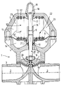
- the valve housing 1 of the diaphragm valve shown consists of three parts, namely a main part 3 having a through-channel 2, a lower part 4 placed thereon and an upper part 5, which are each screwed tightly to one another by means of screws (not shown).
- the through channel 2 of the main part 3 is via a Diaphragm 6 having valve body 7 can be shut off.
- the valve body 7 is carried by a coupling rod 8 which extends through the lower part 4 and also the upper part 5 and is guided displaceably therein.
- a drive unit 22 is provided between the lower part 4 and the upper part 5 of the housing 1 and is connected to the valve body 7 via the coupling rod 8.
- the coupling rod 8 interacts via a thread 9 with a bushing 10 which is arranged between the lower part 4 and the upper part 5 of the valve housing and which further carries a spring plate 11 which on the one hand has a spring assembly 12 'composed of several springs 12 and on the other hand another membrane 13 cooperates, through which the cavity between lower part 4 and upper part 5 is divided into a pressure chamber 14 and a spring chamber 15 for the spring assembly 12 '.
- a bushing 10 which is arranged between the lower part 4 and the upper part 5 of the valve housing and which further carries a spring plate 11 which on the one hand has a spring assembly 12 'composed of several springs 12 and on the other hand another membrane 13 cooperates, through which the cavity between lower part 4 and upper part 5 is divided into a pressure chamber 14 and a spring chamber 15 for the spring assembly 12 '.
- the spring assembly 12 is pretensioned so that the valve body 7 is pressed downward via the spring plate 11 and the coupling rod 8 and the through-channel 2 is closed off. If a pressure medium, for example compressed air or hydraulic oil, is now supplied to the pressure chamber 14, the spring plate 11 with the bushing 10 and thus also the coupling rod 8 with the valve body 7 and the membrane are pressed against the spring force via the membrane 13 6 shifted upwards, opening through channel 2.
- the valve lift is limited by a stop 16 of the bush 10 on the one hand and a stop 17 in the interior of the upper part 5 of the valve housing 1 on the other hand.
- the side edges of the ribs 23 can simultaneously serve to guide the spring assembly 12 '.
- the peripheral edge of the spring plate 11 then serves as a valve body-connected stop 16 'for limiting the valve stroke together with the stops 17'.
- the bushing 10 must then be made somewhat shorter to ensure that only the stops 16 ', 17' come into contact and not the surfaces described above as stops 16, 17.
- the valve lift can be adjusted from the outside by turning the coupling rod 8 via the thread 9.
- the free end of the coupling rod 8 is provided with a means 18 for the attachment of an adjusting tool, not shown.
- an adjusting tool e.g. Key areas in the form of hexagon areas, hexagon area or the like. be provided.
- the lower end of the bushing 10 can serve as a stop 16 ′′, which has an annular surface serving as a counter stop 17 ′′ on the inner upper side of the lower part 2 can work together.
- the dimensions are to be designed in such a way that, with the effective length of the coupling rod 8 set normally, the valve body 7 is seated on its valve seat in the main part 3 in its "closed position" and closes the passage channel 2. There is then still a certain minimum distance between the stops 16 ′′ and 17 ′′.
- the stops 16 ′′, 17 ′′ come to rest in the “closed position” of the drive unit 22 and the valve body 7 can no longer be immersed up to its tightly fitting seat that a minimum flow cross-section remains open when the valve is "closed".
- a minimum flow rate can be set in such a valve or the maximum valve lift and then the maximum flow rate can be limited in a simple manner.
- the end 18 of the coupling rod 8, which carries the means 18 and projects through the upper part 5, serves as a position indicator for the position of the valve body 7 and can be marked accordingly in color for better visibility.
- the penetration of dirt can be prevented by a viewing bell 19 which is attached to the upper part 5 in a manner that can be removed easily to facilitate the adjustment of the stroke, with sufficient space being provided for the end of the coupling rod 8 in the open valve state.
- the coupling rod 8 is rotatably held in the valve body 7 and there can be an indicated rotation lock 20, by means of which an inadvertent adjustment of the stroke limitation (stops 16, 17) is prevented.
- the rotation lock 20 can, for example, be a spring lock snapping into latching recesses. However, any other of the known torque locks that can be overcome by torque can also be used.
- seals 21, preferably round cord seals, are provided between the coupling rod 8, the lower part 4 and the socket 10.
Landscapes
- Engineering & Computer Science (AREA)
- General Engineering & Computer Science (AREA)
- Mechanical Engineering (AREA)
- Mechanically-Actuated Valves (AREA)
- Indication Of The Valve Opening Or Closing Status (AREA)
Claims (8)
- Vanne à membrane, à entraînement pneumatique ou hydraulique, avec un canal de passage (2) pouvant être fermé par un corps de vanne (7), selon laquelle le corps de vanne (7) peut être déplacé par une unité d'entraînement (22) du montant de la course de vanne entre sa "position fermée" et sa "position ouverte", une butée (16, 16') reliée au corps de vanne s'appliquant contre une butée (17, 17') solidaire du boîtier afin de limiter la course du corps de vanne (7), la longueur active de la tige d'accouplement (8) reliant l'unité d'entraînement (22) au corps de vanne (7) pouvant être modifiée et au moins la "position ouverte" du corps de vanne (7) étant alors prédéfinie par une butée fixe (17, 17') et par la longueur active réglée de la tige d'accouplement (8), et une paire supplémentaire de butées (16", 17") étant prévue au voisinage de la "position fermée" du corps de vanne (7), la butée (16") étant reliée au corps de vanne (7) et l'autre butée (17") étant prévue sur le boîtier (1), et la course de fermeture du corps de vanne (7) étant limitée lors de l'application de ces butées (16", 17") l'une contre l'autre, caractérisée en ce qu'une section minimale de passage de la vanne, dépendante de la longueur active réglée de la tige d'accouplement (8), est ouverte par la paire supplémentaire de butées (16", 17") et, lorsque la longueur active de la tige d'accouplement (8) est réglée à une plus grande valeur, le corps de vanne (7) est pressé sur son siège dans la "position fermée" de l'unité d'entraînement (22) et les butées supplémentaires (16", 17") n'entrent alors pas en application mutuelle.
- Vanne à membrane selon la revendication 1, dans laquelle l'unité d'entraînement (22) est disposée entre une partie supérieure (5) et une partie inférieure (4) du boîtier (1), caractérisée en ce que la butée supplémentaire (16"), reliée au corps de vanne, est prévue côté vanne sur l'élément de translation (douille 10) de l'unité d'entraînement (22), et l'autre butée (17"), solidaire du boîtier, de la paire supplémentaire de butées (16", 17"), est prévue sur la face supérieure, traversée par la tige d'accouplement (8), de la partie inférieure (4) du boîtier (1).
- Vanne à membrane selon la revendication 1, caractérisée en ce que plusieurs saillies sont prévues, en étant régulièrement réparties sur la périphérie, dans la partie supérieure (5) du boîtier (1), lesquelles saillies forment conjointement la butée (17') solidaire du boîtier, ces saillies étant de préférence réalisées sous la forme de nervures (23) s'étendant radialement.
- Vanne à membrane selon la revendication 3, caractérisée en ce que les butées (17') solidaires du boîtier coopèrent avec le bord périphérique de la coupelle de ressort (11), lequel bord forme la butée (16') reliée au corps de vanne.
- Vanne à membrane selon l'une quelconque des revendications 1 à 4, avec une membrane supplémentaire (13) traversée par la tige d'accouplement (8), caractérisée en ce que la tige d'accouplement (8) présente un filetage (9) coopérant avec une douille (10), la tige d'accouplement (8) étant en outre solidaire en rotation du corps de vanne.
- Vanne à membrane selon la revendication 5, caractérisée en ce que la douille (10) traverse la membrane supplémentaire (13) et porte une coupelle de ressort (11) pour le ou les ressorts précontraints (12), et en ce que la face de la coupelle de ressort (11) qui est opposée au ressort (12) ou, selon le cas, aux ressorts (12'), sert de face d'appui pour la membrane supplémentaire (13).
- Vanne à membrane selon l'une quelconque des revendications 1 à 6, caractérisée en ce que l'extrémité libre de la tige d'accouplement (8) est amenée à l'extérieur, et cette extrémité libre est pourvue de moyens (18) pour l'application d'un outil rotatif, et en ce que la tige d'accouplement (8) est protégée d'un mouvement intempestif par un blocage en rotation (20) pouvant être surmonté par un certain couple de rotation.
- Vanne à membrane selon la revendication 7, caractérisée en ce que l'extrémité de la tige d'accouplement (8) qui est amenée à l'extérieur est recouverte par une cloche transparente (19), et cette cloche transparente (19) est maintenue sur le boîtier de vanne (1) de façon aisément amovible en vue du réglage de la course ou d'un actionnement manuel d'urgence.
Applications Claiming Priority (2)
| Application Number | Priority Date | Filing Date | Title |
|---|---|---|---|
| DE9207226U | 1992-05-28 | ||
| DE9207226U DE9207226U1 (de) | 1992-05-28 | 1992-05-28 | Membranventil |
Publications (2)
| Publication Number | Publication Date |
|---|---|
| EP0571850A1 EP0571850A1 (fr) | 1993-12-01 |
| EP0571850B1 true EP0571850B1 (fr) | 1996-03-06 |
Family
ID=6879979
Family Applications (1)
| Application Number | Title | Priority Date | Filing Date |
|---|---|---|---|
| EP19930107953 Expired - Lifetime EP0571850B1 (fr) | 1992-05-28 | 1993-05-15 | Vanne à membrane |
Country Status (2)
| Country | Link |
|---|---|
| EP (1) | EP0571850B1 (fr) |
| DE (1) | DE9207226U1 (fr) |
Families Citing this family (6)
| Publication number | Priority date | Publication date | Assignee | Title |
|---|---|---|---|---|
| CH689310A5 (de) | 1994-06-20 | 1999-02-15 | Fischer Georg Rohrleitung | Membranventil. |
| ATE211531T1 (de) * | 1997-08-14 | 2002-01-15 | Fischer Georg Rohrleitung | Membranventil |
| TW418309B (en) | 1998-02-20 | 2001-01-11 | Matsushita Refrigeration | Refrigerator |
| CN108869785A (zh) * | 2018-08-06 | 2018-11-23 | 中国计量大学 | 一种双隔膜背压阀 |
| DE102019129059A1 (de) * | 2019-10-28 | 2021-04-29 | Grohe Ag | Ventil für eine Sanitärarmatur mit einem Membranventil und einem einstellbaren Steuerstab |
| AU2021268798A1 (en) | 2020-05-04 | 2022-12-08 | Aquestia Ltd. | Hydraulically operated valve and systems for use therewith |
Family Cites Families (14)
| Publication number | Priority date | Publication date | Assignee | Title |
|---|---|---|---|---|
| DE503303C (de) * | 1927-10-07 | 1930-07-23 | Josef Muchka | Fernschalteinrichtung fuer Ventile |
| US2270037A (en) * | 1939-12-11 | 1942-01-13 | William C Biddle | Reversible valve |
| US2678662A (en) * | 1950-08-24 | 1954-05-18 | Grinnell Corp | Fluid pressure actuator |
| US3175473A (en) * | 1962-05-01 | 1965-03-30 | Grinnell Corp | Spring and fluid pressure actuator |
| US3180235A (en) * | 1963-02-25 | 1965-04-27 | Honeywell Inc | Controlling apparatus |
| HU162588B (fr) * | 1967-10-20 | 1973-03-28 | ||
| US3451423A (en) * | 1967-12-15 | 1969-06-24 | Hills Mccanna Co | Fluid actuated diaphragm valve |
| DE2241551A1 (de) * | 1972-08-24 | 1974-04-25 | Fritz Mueller | Durchgangsventil |
| US3884446A (en) * | 1973-12-10 | 1975-05-20 | Dahl Co G W | Low profile control valve actuator |
| DE7541730U (de) * | 1975-12-30 | 1977-09-08 | Mueller, Fritz, 7119 Criesbach | Membranventil |
| DE3313896A1 (de) * | 1983-04-16 | 1984-10-18 | Behr-Thomson Dehnstoffregler Gmbh, 7014 Kornwestheim | Thermostatbetaetigtes ventil zur regelung des durchflusses |
| US4708316A (en) * | 1984-12-07 | 1987-11-24 | Canadian Fram Limited | Variable rate EGR valve with step motor control and method therefor |
| DE8620263U1 (de) * | 1986-07-29 | 1986-10-02 | SBS Maschinenfabrik Dr. Hug GmbH, 7080 Aalen | Membranventil |
| DE9013595U1 (de) * | 1990-08-21 | 1990-12-06 | R.C. Mannesmann AG, Basel | Rückflußverhinderer |
-
1992
- 1992-05-28 DE DE9207226U patent/DE9207226U1/de not_active Expired - Lifetime
-
1993
- 1993-05-15 EP EP19930107953 patent/EP0571850B1/fr not_active Expired - Lifetime
Also Published As
| Publication number | Publication date |
|---|---|
| EP0571850A1 (fr) | 1993-12-01 |
| DE9207226U1 (de) | 1992-07-30 |
Similar Documents
| Publication | Publication Date | Title |
|---|---|---|
| DE2305668C2 (de) | Kegelventil | |
| DE2942363C2 (fr) | ||
| DE2312520A1 (de) | Ventilpatrone fuer wasserhaehne o.dgl | |
| DE3877479T2 (de) | Patronenartiges umleitungsventil. | |
| EP0715692B1 (fr) | Soupape de protection de pompe | |
| CH622866A5 (fr) | ||
| DE3687876T2 (de) | Ausladungsventil fuer integrierte lenkeinrichtung. | |
| EP0257014B1 (fr) | Soupape silencieuse | |
| EP0571850B1 (fr) | Vanne à membrane | |
| DE4025654A1 (de) | Ventiloberteil | |
| DE2415146B2 (de) | Berieselungsvorrichtung zum Versprühen von unter Druck stehendem Fluid | |
| DE3233962A1 (de) | Vorrichtung zum steuern eines pneumatischen geraets | |
| DE2830891A1 (de) | Sicherheitsventil | |
| DE102005052385B4 (de) | Druckminderer | |
| EP1462692A1 (fr) | Tête de robinet | |
| DE2750502A1 (de) | Hydraulikventil | |
| EP3265704B1 (fr) | Pièce supérieure de soupape pour robinetterie | |
| EP0178599B1 (fr) | Vanne de réglage, en particulier vanne d'étranglement | |
| DE2050025B2 (de) | Eingriff Mischbatterie | |
| DE69227256T2 (de) | Mengen-und temperaturbegrenzungsvorrichtung fuer ein mischventil | |
| DE2413692C3 (de) | Rückschlagventil mit zusätzlicher Druckmittelbetätigung | |
| DE573490C (de) | Fluessigkeitsstossdaempfer, insbesondere fuer Kraftfahrzeuge | |
| DE444884C (de) | Bremsvorrichtung fuer Rohrbruchventile oder -klappen | |
| DE69504292T2 (de) | Sicherheitsventil | |
| DE10132107B4 (de) | Vorrichtung zum gesteuerten Bremsen der Aufwickelbewegung eines Springrollos |
Legal Events
| Date | Code | Title | Description |
|---|---|---|---|
| PUAI | Public reference made under article 153(3) epc to a published international application that has entered the european phase |
Free format text: ORIGINAL CODE: 0009012 |
|
| AK | Designated contracting states |
Kind code of ref document: A1 Designated state(s): ES FR GB IT |
|
| 17P | Request for examination filed |
Effective date: 19931015 |
|
| 17Q | First examination report despatched |
Effective date: 19950210 |
|
| GRAA | (expected) grant |
Free format text: ORIGINAL CODE: 0009210 |
|
| AK | Designated contracting states |
Kind code of ref document: B1 Designated state(s): ES FR GB IT |
|
| PG25 | Lapsed in a contracting state [announced via postgrant information from national office to epo] |
Ref country code: IT Free format text: LAPSE BECAUSE OF FAILURE TO SUBMIT A TRANSLATION OF THE DESCRIPTION OR TO PAY THE FEE WITHIN THE PRE;WARNING: LAPSES OF ITALIAN PATENTS WITH EFFECTIVE DATE BEFORE 2007 MAY HAVE OCCURRED AT ANY TIME BEFORE 2007. THE CORRECT EFFECTIVE DATE MAY BE DIFFERENT FROM THE ONE RECORDED.SCRIBED TIME-LIMIT Effective date: 19960306 Ref country code: ES Free format text: THE PATENT HAS BEEN ANNULLED BY A DECISION OF A NATIONAL AUTHORITY Effective date: 19960306 |
|
| GBT | Gb: translation of ep patent filed (gb section 77(6)(a)/1977) |
Effective date: 19960319 |
|
| ET | Fr: translation filed | ||
| PLBE | No opposition filed within time limit |
Free format text: ORIGINAL CODE: 0009261 |
|
| 26N | No opposition filed | ||
| PGFP | Annual fee paid to national office [announced via postgrant information from national office to epo] |
Ref country code: GB Payment date: 19980429 Year of fee payment: 6 |
|
| PGFP | Annual fee paid to national office [announced via postgrant information from national office to epo] |
Ref country code: FR Payment date: 19980518 Year of fee payment: 6 |
|
| PG25 | Lapsed in a contracting state [announced via postgrant information from national office to epo] |
Ref country code: GB Free format text: LAPSE BECAUSE OF NON-PAYMENT OF DUE FEES Effective date: 19990515 |
|
| GBPC | Gb: european patent ceased through non-payment of renewal fee |
Effective date: 19990515 |
|
| PG25 | Lapsed in a contracting state [announced via postgrant information from national office to epo] |
Ref country code: FR Free format text: LAPSE BECAUSE OF NON-PAYMENT OF DUE FEES Effective date: 20000131 |
|
| REG | Reference to a national code |
Ref country code: FR Ref legal event code: ST |