EP0572068B1 - Dispositif pour la traite automatique d'animaux - Google Patents
Dispositif pour la traite automatique d'animaux Download PDFInfo
- Publication number
- EP0572068B1 EP0572068B1 EP93201420A EP93201420A EP0572068B1 EP 0572068 B1 EP0572068 B1 EP 0572068B1 EP 93201420 A EP93201420 A EP 93201420A EP 93201420 A EP93201420 A EP 93201420A EP 0572068 B1 EP0572068 B1 EP 0572068B1
- Authority
- EP
- European Patent Office
- Prior art keywords
- construction
- animal
- cleaning member
- milkbox
- recording means
- Prior art date
- Legal status (The legal status is an assumption and is not a legal conclusion. Google has not performed a legal analysis and makes no representation as to the accuracy of the status listed.)
- Expired - Lifetime
Links
- 241001465754 Metazoa Species 0.000 title claims description 69
- 238000010276 construction Methods 0.000 title claims description 61
- 238000004140 cleaning Methods 0.000 claims description 77
- 210000002445 nipple Anatomy 0.000 claims description 35
- 210000000481 breast Anatomy 0.000 claims description 24
- 239000004753 textile Substances 0.000 claims description 18
- 241000283690 Bos taurus Species 0.000 claims description 16
- 239000000463 material Substances 0.000 claims description 3
- 229920003002 synthetic resin Polymers 0.000 claims description 2
- 239000000057 synthetic resin Substances 0.000 claims description 2
- 210000003141 lower extremity Anatomy 0.000 claims 1
- 239000000696 magnetic material Substances 0.000 claims 1
- 230000037396 body weight Effects 0.000 description 6
- 230000000249 desinfective effect Effects 0.000 description 4
- 230000009471 action Effects 0.000 description 2
- 230000000994 depressogenic effect Effects 0.000 description 2
- 230000000694 effects Effects 0.000 description 2
- 230000036541 health Effects 0.000 description 2
- 230000006651 lactation Effects 0.000 description 2
- 241000283707 Capra Species 0.000 description 1
- CWYNVVGOOAEACU-UHFFFAOYSA-N Fe2+ Chemical compound [Fe+2] CWYNVVGOOAEACU-UHFFFAOYSA-N 0.000 description 1
- 230000008901 benefit Effects 0.000 description 1
- 230000008859 change Effects 0.000 description 1
- 238000011109 contamination Methods 0.000 description 1
- 230000007423 decrease Effects 0.000 description 1
- 239000007788 liquid Substances 0.000 description 1
- 239000008267 milk Substances 0.000 description 1
- 210000004080 milk Anatomy 0.000 description 1
- 235000013336 milk Nutrition 0.000 description 1
- 230000000149 penetrating effect Effects 0.000 description 1
- 230000004044 response Effects 0.000 description 1
Images

Classifications
-
- A—HUMAN NECESSITIES
- A01—AGRICULTURE; FORESTRY; ANIMAL HUSBANDRY; HUNTING; TRAPPING; FISHING
- A01J—MANUFACTURE OF DAIRY PRODUCTS
- A01J5/00—Milking machines or devices
- A01J5/017—Automatic attaching or detaching of clusters
- A01J5/0175—Attaching of clusters
-
- A—HUMAN NECESSITIES
- A01—AGRICULTURE; FORESTRY; ANIMAL HUSBANDRY; HUNTING; TRAPPING; FISHING
- A01J—MANUFACTURE OF DAIRY PRODUCTS
- A01J7/00—Accessories for milking machines or devices
- A01J7/04—Accessories for milking machines or devices for treatment of udders or teats, e.g. for cleaning
Definitions
- the invention relates to a construction for automatically milking animals, such as cows, comprising a milkbox extending in a longitudinal direction and a milking machine, as well as a cleaning member for cleaning the udder and/or teats of an animal, which cleaning member during operation is rotatable and in movable in a direction which deviates from the longitudinal direction of the milkbox.
- Such a construction is known from the European patent application 0 476 771.
- the cleaning members can be rotated around a vertical pivotal axis.
- This has the disadvantage that at the start of the rotation the component of lateral movement is 100%, while this component of movement gradually decreases.
- the construction has further the disadvantage that, during cleaning of the teats, the cleaning member is attached to a robot arm end portion which is rotatable around said vertical pivotal axis. This results in that during cleaning of the teats of the animal the whole robotarm end portion together with the cleaning members has to be rotated about said vertical pivotal axis. Therefore, relatively powerful cylinders are necessary, while the movement of the cleaning members is relatively slow, due to the large and heavy construction.
- the said construction has furthermore the disadvantage that during cleaning, part of the robotarm construction has to be moved in order to move the cleaning member.
- the invention has for its object to provide a cleaning unit of the type described, in which the said disadvantages do not occur or are at least prevented to a certain extent.
- a construction as defined in the opening paragraph is, according to the invention, characterized in that the cleaning member is attached to a slide, mounted movable in the lateral direction of the milkbox, by means of which the cleaning member is movable in a lateral direction during the cleaning of the udder and/or teats of the animal.
- the cleaning member is rotatable during operation in two directions.
- the cleaning member includes at least one shaft which extends in the longitudinal direction of the milkbox. During cleaning, the shaft is inserted between the front and rear teats and moved towards a side of the animal. When the cleaning member rotates clockwise, then preferably the cleaning member is moved from the centre position to the right-hand side of the animal (taken from the rear of the animal). After the cleaning member has passed the teats, the direction of rotation of the cleaning member is reversed, as a result of which it rotates anti-clockwise. Thereafter the cleaning member is moved to the centre position, so that the other side of the teats are cleaned during this motion. Thus, an adequate cleaning of both sides of the teats is obtained.
- a particularly advantageous effect is obtained with the construction in accordance with the invention when the shaft of the cleaning member is hollow and is provided with perforations; this renders it namely possible to pass a cleaning and/or disinfecting solution through the perforations during the cleaning operation.
- the shaft of the cleaning member is driven by a pneumatic motor.
- a plurality of textile discs are provided on the shaft of the cleaning member. The textile discs are spaced apart, so that during cleaning a teat is cleaned between two adjacently arranged textile discs, the discs operating with a rubbing motion.
- the cleaning member includes a four-hinge linkage construction.
- the implement further includes pressure adjusting means, with the aid of which the pressure with which an operating cylinder pushes the cleaning member against the animal's udder can be adjusted.
- the cleaning member includes a pneumatic shifting member, by means of which the cleaning member is movable during operation.
- the cleaning member is attached to a slide extending in the transverse direction of the milkbox.
- the implement in accordance with the invention can be further provided with first positioning means.
- the cleaning member is mounted on a robot arm construction, which is rotatable through at least 180° about a vertical shaft.
- the construction in accordance with the invention can further include recording means arranged in or on the milkbox floor, with the aid of which, on the basis of the position of an animal's leg on the floor, the location of the udder and/or the teats can be determined.
- the recording means have a surface area which has at least a size equal to the surface area of the bottom side of the leg of the animal to be milked.
- a relatively large surface area with recording means has the advantage that each time the animal enters the milkbox, it is not necessary to take measures to ensure that the animal always takes up a position precisely on the recording means.
- the invention therefore also relates to a construction for automatically milking animals, such as cows, comprising a milkbox and a milking machine, characterized in that the floor of the milkbox is equipped with recording means, by means of which the weight of an animal in the milkbox can be determined.
- the recording means are depressible.
- the recording means are provided in four locations in or on the floor, on which the animals' legs bear when the animal is in the milkbox.
- the construction includes an animal identification system in which data about the position of the udder of an animal can be stored and from which the data can be read.
- the construction includes second positioning means which, together with the recording means, can determine the position of a leg of an animal in the milkbox. When an animal enters the milkbox, then, on the basis of a transponder attached to the animal's neck and the identification system, it can be determined which animal is concerned and also the position of the udder and/or the teats relative to a leg of the relevant animal.
- the position of the leg of the animal in the milkbox floor can be determined with the recording means, as a result of which in combination with the data of the animal identification system, also the position of the udder and/or the teats of the relevant animal is known.
- the cleaning member and/or a milk cluster can thereafter be moved up to the udder and/or teats.
- the signal produced by the recording means is applied to a computer and stored in a memory.
- the computer determines the weight of the relevant animal.
- the farmer can read the weight of the animal on a display of the computer. Each time the animal enters the milkbox, the weight is determined and stored. In this manner the farmer can read from the memory the change in weight of each animal during, for example, an X-number of days. From this body weight record the farmer can, for example, derive in which stage of the lactation cycle the animal is, so that he knows when the cow is "dry".
- the body weight record can in some cases also be an indication of the health condition of the animal.
- Figure 1 shows a milkbox 1 in which a cow 2 is present.
- a feed trough 6 and expelling means 7 are further attached to the frame 3.
- the first robot arm construction 9 includes a first sliding block 11 which is fitted on the frame beam 8 and is movable in the longitudinal direction of the milkbox 1 over the frame beam 8.
- the first sliding block 11 includes a first vertical shaft 12, about which a first horizontally directed beam 13 can be pivoted.
- a milking machine 15 is attached to the frame beam 8 by means of a second robot arm construction 14.
- the second robot arm construction 14 includes a second sliding block 16 which has a second vertical shaft 17, about which a second horizontal beam 18 is arranged pivotably.
- the milking machine 15 comprises four teat cups 19.
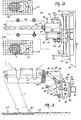
- FIG 2 shows the cleaning member 10 to an enlarged scale.
- the cleaning member 10 includes a hollow shaft 20 which at its circumference is provided with perforations 21.
- textile discs 22 are mounted on the hollow shaft 20.
- the textile discs 22 are slightly interspaced, so that there is a clearance between two adjoining textile discs 22.
- the textile discs 22 are clamped on the hollow shaft 20 between two nuts 23 located at the two ends of the hollow shaft 20.
- the perforations 21 in the hollow shaft 20 are in a position in which an intermediate space is formed by two adjoining textile discs 22.
- a cleaning and/or disinfecting solution can be sprayed during cleaning of the teats and/or the udder into the intermediate spaces between two adjoining textile discs 22 via the perforations 21.
- the cleaning and/or disinfecting solution is fed to the hollow shaft 20 via a first supply line 24.
- the hollow shaft 20 is driven by a pneumatic motor 25 which is drivable in two directions.
- the pneumatic motor 25 has a first air supply line 26 and a second air supply line 27.
- the hollow shaft 20 will start to rotate clockwise, wheras, when compressed air is supplied to the pneumatic motor 25 via the second air supply line 27, the hollow shaft 20 will start to rotate anti-clockwise.
- electric or hydraulic motor may alternatively be used instead of a pneumatic motor.
- a vertical plate 28 is provided at one side of the pneumatic motor 25. Via a four-hinge linkage construction 29, the vertical plate 28 is connected to a slide 30.
- the four-hinge linkage construction 29 comprises two strips 31 which extend in parallel and at some distance from each other and at their ends are connected pivotably to horizontal pivot shafts 32.
- the strips 31 have one end connected to the vertical plate 28 and their other end to a block 33 forming part of the slide 30.
- Disposed between the two strips 31 is moreover an operating cylinder 34, with the aid of which the four-hinge linkage construction 29 is movable in height.
- the operating cylinder 34 is, preferably, a pneumatic cylinder.
- the slide 30 includes a vertical strip 35 which is rigidly connected to the first beam 13 of the first robot arm construction 9. At both ends, the vertical strip 35 is provided with rectangular blocks 36 which are attached vertically and at a square angle to the strip 35. Two horizontal guide rails 37, which are located remote from each other and one below the other, are positioned between the two rectangular blocks 36. In addition, a horizontal cylinder 38, which by means of its two ends is also connected to the rectangular blocks 36, is accommodated between the two guide rails 37.
- the block 33 connected to the four-hinge linkage construction 29 is arranged such that it is slidable over the guide rails 37 and the cylinder 38.
- the cylinder 38 contains a movable, rod-like free piston 39 which has a diameter approximately equal to the inner diameter of the cylinder 38.
- the free piston 39 is made of a magnetic meterial, and the cylinder 38 is made of a synthetic resin material.
- the cylinder 38 is provided with a third air supply line 40, whilst a fourth air supply line 41 is attached to the other end.
- the block 33 connected to the four-hinge linkage construction 29 is made of a ferrous material, so that the block 33 tracks the motion of the free piston 39. As a result thereof, it is possible to reciprocate the cleaning member 10 in operation along the slide 30 in the transverse direction of the milkbox 1.
- first positioning means 42 are present.
- the first positioning means 42 include a coding strip 43 which is positioned against the vertical strip 35 and substantially extends through the overall width of the cylinder 38.
- the first positioning means 42 further include, disposed on the block 33, a read sensor 44 with the aid of which the coding strip 43 is scannable. The signal produced by the read sensor 44 is applied to a computer, not further shown, with the aid of which the position of the cleaning member 10 on the slide 30 can be determined.
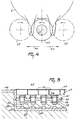
- the construction such as it is shown in Figure 1, further includes recording means 45 which in the embodiment are incorporated in the floor 46 of the milkbox 1. As is shown in Figure 3, the recording means 45 are arranged in a depression in the floor 46, so that the recording means 45 are flush with the floor 46. It will, however, be obvious that the recording means 45 may alternatively be arranged on the floor 46 of the milkbox 1.
- the recording means 45 are constituted by piezo-electric elements which are known per se.
- the recording means 45 are positioned in four locations in the floor 46 of the milkbox 1.
- the locations, in which the recording means 45 are provided have been chosen such that, when an animal assumes a posture in the milkbox 1, it stands with its legs on all four recording means 45.
- the width of the surface area in which the recording means 45 are accommodated amounts to 25 cms, whereas the length is approximately 50 cms. It will be obvious that in given circumstances, for example for milking animals of a different type (goats), it is possible to deviate from the said dimensions.
- the recording means 45 comprises a plurality of pressure-responsive elements 47 which are arranged in a side-by-side relationship.
- the pressure-responsive elements 47 are formed by electromechanical contacts.
- the electromechanical contacts are disposed in a depression 48 in the floor 46.
- a plate 51 is disposed which is provided with bores 50 and on which the individual pressure-responsive elements 47 are attached.
- Each of the pressure-responsive elements 47 includes a square block 52 which is provided with a vertical rod 53.
- a pressure spring 54 is pushed over the vertical rod 53.
- Each vertical rod 53 is inserted through a bore 50 in the plate 51 and locked at the bottom side by a locking washer 55.
- the pressure springs 54 are thereby confined between the bottom end of a block 52 and the upper side of the plate 51.
- the vertical rods 53 are slightly bevelled and provided with a first contact plane 56, to which a first electric lead 57 is connected.
- a second contact plane 58 is provided, to which a second electric lead 59 is connected. In the rest condition, the first contact plane 56 is at some distance from the second contact plane 58.
- the upper side of the pressure-responsive elements 47 is covered with a film layer 60.
- the construction in accordance with the invention further may include an animal identification system 61, which in the embodiment shown in Figure 1 is attached to the frame beam 8.
- the animal identification system 61 responds to a transponder 62 provided around the neck of the cow 2.
- the animal identification system 61 receives from the transponder 62 a code which is unique for the cow 2. On the basis of this code, a computer connected to the animal identification system 61 determines which cow 2 has taken place in the milkbox 1. In the computer, not shown, all the data known of the animal are read from the computer memory and kept ready for use.
- the recording means 45 are energized, since the cow 2 stands with its legs on the recording means 45. As the surface area of the recording means 45 is many times larger than the surface area of the bottom side of the legs of the cow 2, only a number of piezoelectric elements or pressure-responsive elements 47 are depressed, against the action of a spring.
- the piezoelectric elements or pressure-responsive elements 47 depressed by the legs of the cow 2 apply a signal to the computer, on the basis of which the position of the legs of the cow 2 on the floor 46 of the milkbox 1 can accurately be determined. To that end, the position of each piezoelectric and/or pressure-responsive element 47 is recorded in the memory of the computer. Additionally, in the computer memory is stored the position of the udder and/or teats of each animal with respect to one or more legs of the relevant animal. When the position of one or more legs has been determined with the aid of the signals supplied by the recording means 45, then for the relevant cow the position of the udder and/or teats is read from the computer memory.
- the cleaning member 10 is moved with the aid of the first robot arm construction 9 to the udder and/or teats.
- the first sliding block 11 is moved along the frame beam 8 and the first robot arm construction 9 pivots about the first vertical shaft 12, whilst simultaneously the block 33 is moved along the slide 30.
- the distance through which the first sliding block 11 and the block 33 are moved, is determined on the basis of the coordinates, corresponding to the position of the udder and/or teats, of the relevant cow.
- the cleaning member 10 is positioned such that the hollow shaft 20 bearing the textile discs 22 arrives in the longitudinal direction of the milkbox 1 between the teats.
- This starting state 63 is illustrated in Figure 4 by solid lines.
- the pneumatic motor 25 is made operative by applying compressed air via the first air supply line 26.
- the textile discs 22 rotate clockwise.
- the hollow shaft 20 is moved in the direction of the first arrow 64.
- the direction of rotation of the pneumatic motor 25 is reversed (the textile discs 22 rotate anti-clockwise) by energizing the second air supply line 27.
- the hollow shaft 20 bearing the textile discs 22 is moved towards the starting position 63.
- the motion in the direction indicated by the second arrow 66 is continued, after the starting position 63 has been reached, until the textile discs 22 have arrived in the position indicated in Figure 4 by second broken lines 67. Thereafter the direction of rotation is reversed (the textile discs 22 rotate clockwise) and the hollow shaft 20 equipped with the textile discs 22 is moved towards the starting position 63.
- the hollow shaft 20 can be reciprocated slightly in the longitudinal direction of the milkbox, whereby a still more intensive cleaning of the udder and/or teats can be obtained.
- the first sliding block 11 is moved in the direction of the third arrow 68 shown in Figure 1.
- the robot arm construction 9 is rotated through 180° about the first vertical shaft 12 in the direction of the fourth arrow 69, whereafter the first sliding block 11 is moved in the direction of the fifth arrow 70.
- the teat cups 19 are connected to the teats. Positioning of the teat cups 19 is effected in the same manner as positioning the cleaning member 10.
- the body weight of each animal is determined, after it has taken place in the milkbox 1.
- the determination of the body weight of the animal is effected with the aid of the four recording means 45 on which the animal's legs bear.
- the body weight of the animal is determined again and stored in the computer. In this manner the farmer can obtain a body weight status of each animal, which provides him with, for example, information about the lactation period of the relevant animal and/or the health condition of the animal.
Landscapes
- Life Sciences & Earth Sciences (AREA)
- Animal Husbandry (AREA)
- Environmental Sciences (AREA)
- Housing For Livestock And Birds (AREA)
- Cleaning In General (AREA)
- Catching Or Destruction (AREA)
- Refuse Collection And Transfer (AREA)
- Dairy Products (AREA)
- Geophysics And Detection Of Objects (AREA)
Claims (24)
- Dispositif pour la traite automatique d'animaux, tels que des vaches, comprenant une stalle de traite (1) s'étendant dans un sens longitudinal et une machine à traire, ainsi qu'un organe de nettoyage (10) pour nettoyer le pis et/ou les trayons d'un animal, lequel organe de nettoyage (10) est, pendant le fonctionnement, rotatif et est mobile dans une direction qui dévie de la direction longitudinale de la stalle de traite (1),
caractérisé en ce que l'organe de nettoyage (10) est attaché à une glissière (30) montée mobile dans le sens latéral de la stalle de traite (1), au moyen de laquelle l'organe de nettoyage (10) est mobile dans un sens latéral pendant le nettoyage du pis et/ou des trayons de l'animal. - Dispositif selon la revendication 1, caractérisé en ce que l'organe de nettoyage (10) comporte au moins un arbre (20) qui s'étend dans le sens longitudinal de la stalle de traite (1).
- Dispositif selon la revendication 2, caractérisé en ce que, pendant le fonctionnement, l'arbre (20) de l'organe de nettoyage (10) peut tourner alternativement dans le sens contraire à celui des aiguilles d'une montre et dans le sens des aiguilles d'une montre.
- Dispositif selon la revendication 2 ou 3, caractérisé en ce que l'organe de nettoyage (10) comprend une pluralité de disques textiles (22).
- Dispositif selon l'une quelconque des revendications précédentes, caractérisé en ce que l'organe de nettoyage (10) comporte une structure de liaison (29) à quatre articulations pour mouvoir l'organe de nettoyage (10) dans un sens vers le haut.
- Dispositif selon la revendication 5, caractérisé en ce que le dispositif comporte un moyen de réglage de pression à l'aide duquel la pression avec laquelle le vérin actionneur (34) pousse l'organe de nettoyage (10) contre le pis de l'animal peut être réglée.
- Dispositif selon la revendication 5 ou 6, caractérisé en ce que le vérin actionneur (34) est conçu comme un vérin pneumatique.
- Dispositif selon l'une quelconque des revendications précédentes, caractérisé en ce que, dans le fonctionnement, l'organe de nettoyage (10) peut être animé d'un mouvement alternatif dans le sens longitudinal de la stalle de traite (1).
- Dispositif selon la revendication 8, caractérisé en ce que l'organe de nettoyage (10) est attaché à une glissière (30) s'étendant dans le sens transversal de la stalle de traite (1).
- Dispositif selon la revendication 9, caractérisé en ce que la glissière (30) comporte un bloc (33) qui est coulissant sur des rails de guidage (37).
- Dispositif selon la revendication 10, caractérisé en ce que le bloc coulissant (33) comporte un premier moyen de positionnement (42) avec lequel la position du bloc (33) par rapport aux rails de guidage (37) peut être déterminée.
- Dispositif selon la revendication 11, caractérisé en ce que le bloc coulissant (33) est aussi coulissant sur un cylindre (38) qui contient un piston (39) supporté librement, qui est fait de matériau magnétique .
- Dispositif selon la revendication 12, caractérisé en ce que le cylindre (38) contenant le piston (39) supporté librement est fait de matériau en résine synthétique.
- Dispositif selon l'une quelconque des revendications précédentes, caractérisé en ce que l'organe de nettoyage (10) est attaché à une structure (9) du bras de robot qui peut être tournée d'au moins 180° autour d'un arbre vertical (12).
- Dispositif selon l'une quelconque des revendications précédentes, caractérisé en ce que la structure (9) comporte des moyens d'enregistrement (45) qui sont logés dans le plancher (46) de la stalle de traite (1) ou sur ce plancher, et avec lesquels, d'après la position d'une patte d'un animal sur le plancher (46), l'emplacement du pis et/ou des trayons de l'animal concerné peut être déterminé.
- Dispositif selon la revendication 15, caractérisé en ce que, à l'aide de moyens d'enregistrement (45) il est possible de déterminer le poids d'un animal se tenant debout dans la stalle de traite.
- Dispositif selon la revendication 15 ou 16, caractérisé en ce que les moyens d'enregistrement (45) sont dépressibles.
- Dispositif selon l'une quelconque des revendications 15 à 17, caractérisé en ce que les moyens d'enregistrement (45) sont logés en quatre emplacements dans le plancher (46) ou sur celui-ci, sur lesquels portent les pattes d'un animal quand l'animal se tient debout dans la stalle de traite (1).
- Dispositif selon l'une quelconque des revendications 15 à 18, caractérisé en ce que les moyens d'enregistrement (45) comprennent des éléments pièzo-électriques (47).
- Dispositif selon la revendication 19, caractérisé en ce qu'en utilisant des deuxièmes moyens de positionnement (62) et les éléments pièzo-électriques (47), la position d'une patte postérieure d'un animal dans la stalle de traite (1) peut être déterminée.
- Dispositif selon la revendication 20, caractérisé en ce que le plancher (46) de la stalle de traite comporte des éléments (47) sensibles à la pression, qui comprennent des contacts électromécaniques.
- Dispositif selon la revendication 20 ou 21, caractérisé en ce que les éléments (47) sensibles à la pression ou les éléments pièzo-électriques (47) fournissent un signal d'après lequel le poids d'un animal peut être déterminé.
- Dispositif selon la revendication 22, caractérisé en ce que les signaux fournis par les éléments (47) sensibles à la pression ou par les éléments pièzo-électriques (47) sont introduits dans un ordinateur et conservés dans une mémoire.
- Dispositif selon la revendication 23, caractérisé en ce que, en plus du poids d'un animal, aussi l'identité de l'animal déterminée d'après des signaux fournis par un émetteur-récepteur (62) autour de l'encolure de l'animal concerné est conservée dans la mémoire de l'ordinateur.
Priority Applications (2)
| Application Number | Priority Date | Filing Date | Title |
|---|---|---|---|
| EP97203757A EP0834250B1 (fr) | 1992-05-26 | 1993-05-18 | Installation de traite automatique d'animaux |
| EP00203705A EP1086622B1 (fr) | 1992-05-26 | 1993-05-18 | Dispositif de traite automatique d'animaux |
Applications Claiming Priority (2)
| Application Number | Priority Date | Filing Date | Title |
|---|---|---|---|
| NL9200924A NL9200924A (nl) | 1992-05-26 | 1992-05-26 | Inrichting voor het automatisch melken van dieren. |
| NL9200924 | 1992-05-26 |
Related Child Applications (2)
| Application Number | Title | Priority Date | Filing Date |
|---|---|---|---|
| EP97203757A Division EP0834250B1 (fr) | 1992-05-26 | 1993-05-18 | Installation de traite automatique d'animaux |
| EP00203705A Division EP1086622B1 (fr) | 1992-05-26 | 1993-05-18 | Dispositif de traite automatique d'animaux |
Publications (3)
| Publication Number | Publication Date |
|---|---|
| EP0572068A2 EP0572068A2 (fr) | 1993-12-01 |
| EP0572068A3 EP0572068A3 (fr) | 1993-12-08 |
| EP0572068B1 true EP0572068B1 (fr) | 1998-08-12 |
Family
ID=19860839
Family Applications (3)
| Application Number | Title | Priority Date | Filing Date |
|---|---|---|---|
| EP97203757A Expired - Lifetime EP0834250B1 (fr) | 1992-05-26 | 1993-05-18 | Installation de traite automatique d'animaux |
| EP93201420A Expired - Lifetime EP0572068B1 (fr) | 1992-05-26 | 1993-05-18 | Dispositif pour la traite automatique d'animaux |
| EP00203705A Expired - Lifetime EP1086622B1 (fr) | 1992-05-26 | 1993-05-18 | Dispositif de traite automatique d'animaux |
Family Applications Before (1)
| Application Number | Title | Priority Date | Filing Date |
|---|---|---|---|
| EP97203757A Expired - Lifetime EP0834250B1 (fr) | 1992-05-26 | 1993-05-18 | Installation de traite automatique d'animaux |
Family Applications After (1)
| Application Number | Title | Priority Date | Filing Date |
|---|---|---|---|
| EP00203705A Expired - Lifetime EP1086622B1 (fr) | 1992-05-26 | 1993-05-18 | Dispositif de traite automatique d'animaux |
Country Status (3)
| Country | Link |
|---|---|
| EP (3) | EP0834250B1 (fr) |
| DE (3) | DE69333474T2 (fr) |
| NL (1) | NL9200924A (fr) |
Families Citing this family (13)
| Publication number | Priority date | Publication date | Assignee | Title |
|---|---|---|---|---|
| NL9301098A (nl) * | 1993-06-24 | 1995-01-16 | Texas Industries Inc | Inrichting voor het automatisch melken van dieren. |
| NL9301414A (nl) * | 1993-08-16 | 1995-03-16 | Lely Nv C Van Der | Inrichting voor het automatisch melken van dieren. |
| NL9401802A (nl) * | 1994-10-31 | 1996-06-03 | Maasland Nv | Inrichting voor het melken van dieren. |
| NL1000010C2 (nl) * | 1995-04-03 | 1996-10-04 | Maasland Nv | Werkwijze voor het positioneren van voor het automatisch melken benodigde middelen onder de uier van een dier, alsmede inrichting waarin deze werkwijze kan worden toegepast. |
| NL1002471C2 (nl) * | 1996-02-28 | 1997-08-29 | Maasland Nv | Werkwijze voor het verzorgen, in het bijzonder het voeren, van dieren. |
| SE9603077D0 (sv) * | 1996-08-29 | 1996-08-29 | Tetra Laval Holdings & Finance | An apparatus for and a method of performing an animal-related action regarding at least a part of the body of an animal |
| SE9702837D0 (sv) | 1997-07-31 | 1997-07-31 | Alfa Laval Agri Ab | Teat cleaning device and method |
| NL1011255C2 (nl) * | 1999-02-09 | 2000-08-10 | Maasland Nv | Werkwijze voor het bepalen van de te verwachten speenpositie van een dier. |
| SE517531C2 (sv) * | 1999-05-06 | 2002-06-18 | Alfa Laval Agri Ab | Anordning och förfarande för rengöring av spenar |
| NL1019117C2 (nl) | 2001-10-05 | 2003-04-09 | Lely Entpr Ag | Inrichting en werkwijze voor het uitvoeren van een diergerelateerde behandeling op een dier. |
| NL1020148C2 (nl) | 2002-03-11 | 2003-09-18 | Lely Entpr Ag | Inrichting en samenstel voor een diergerelateerde handeling. |
| NL1036353C2 (nl) * | 2008-12-22 | 2010-06-23 | Lely Patent Nv | Kreupelheiddetector. |
| CN116058296B (zh) * | 2023-03-07 | 2023-06-06 | 山东畜牧兽医职业学院 | 一种马属动物体表寄生虫清理机 |
Citations (2)
| Publication number | Priority date | Publication date | Assignee | Title |
|---|---|---|---|---|
| EP0313109A1 (fr) * | 1985-03-12 | 1989-04-26 | C. van der Lely N.V. | Dispositif de traite d'animaux |
| EP0535755A2 (fr) * | 1991-10-04 | 1993-04-07 | Texas Industries Inc. | Dispositif pour nettoyer les pis des animaux produisant du lait |
Family Cites Families (12)
| Publication number | Priority date | Publication date | Assignee | Title |
|---|---|---|---|---|
| DE1607165A1 (de) * | 1967-03-09 | 1970-07-09 | Filippov Vladimir N | Selbsttaetig gesteuerte Einrichtung zur oberflaechlichen Behandlung von Saeugetieren mit Fluessigkeit,Pulver,Dampf oder Gas |
| SU374883A1 (ru) * | 1971-11-09 | 1984-10-23 | Государственное Специальное Конструкторское Бюро По Комплексу Машин Для Ферм Крупного Рогатого Скота | Устройство дл санитарной обработки животных |
| FR2501965A1 (fr) * | 1981-03-17 | 1982-09-24 | Jardin Marc | Appareil portatif pour effectuer en continu des operations de nettoyage, de rincage, de sechage et de massage, applicable notamment aux animaux en lactation |
| SE430559B (sv) * | 1982-04-08 | 1983-11-28 | Alfa Laval Ab | Sett att mjolka och anordning herfor |
| NL8304498A (nl) * | 1983-12-30 | 1985-07-16 | Ir Roelof Geert Middel En Rink | Inrichting voor het melken van vee en werkwijze voor het bedrijven van een dergelijke inrichting. |
| FR2559351B1 (fr) * | 1984-02-09 | 1986-10-24 | Marquaire Pierre | Dispositif pour laver et desinfecter les trayons avant la traite |
| US4617876A (en) * | 1984-11-28 | 1986-10-21 | Hayes Norman J | Animal identification and control system |
| ATE74254T1 (de) * | 1985-01-16 | 1992-04-15 | Lely Nv C Van Der | Geraet und verfahren zum melken von tieren, wie z.b kuehen. |
| DE3774217D1 (de) * | 1986-08-27 | 1991-12-05 | Lely Nv C Van Der | Geraet zum melken von tieren. |
| NL8702285A (nl) * | 1987-09-24 | 1989-04-17 | Gascoigne Melotte Bv | Melkinrichting. |
| FR2630298B3 (fr) * | 1988-04-25 | 1990-04-20 | Goiset Paul | Support mobile de lavage |
| NL9002047A (nl) * | 1990-09-18 | 1992-04-16 | Lely Nv C Van Der | Reinigingsinstallatie. |
-
1992
- 1992-05-26 NL NL9200924A patent/NL9200924A/nl not_active Application Discontinuation
-
1993
- 1993-05-18 DE DE1993633474 patent/DE69333474T2/de not_active Expired - Fee Related
- 1993-05-18 EP EP97203757A patent/EP0834250B1/fr not_active Expired - Lifetime
- 1993-05-18 DE DE1993620254 patent/DE69320254T2/de not_active Expired - Fee Related
- 1993-05-18 EP EP93201420A patent/EP0572068B1/fr not_active Expired - Lifetime
- 1993-05-18 DE DE1993630439 patent/DE69330439T2/de not_active Expired - Fee Related
- 1993-05-18 EP EP00203705A patent/EP1086622B1/fr not_active Expired - Lifetime
Patent Citations (2)
| Publication number | Priority date | Publication date | Assignee | Title |
|---|---|---|---|---|
| EP0313109A1 (fr) * | 1985-03-12 | 1989-04-26 | C. van der Lely N.V. | Dispositif de traite d'animaux |
| EP0535755A2 (fr) * | 1991-10-04 | 1993-04-07 | Texas Industries Inc. | Dispositif pour nettoyer les pis des animaux produisant du lait |
Also Published As
| Publication number | Publication date |
|---|---|
| EP0572068A2 (fr) | 1993-12-01 |
| EP0834250A2 (fr) | 1998-04-08 |
| DE69333474D1 (de) | 2004-05-06 |
| NL9200924A (nl) | 1993-12-16 |
| DE69333474T2 (de) | 2005-04-14 |
| EP0834250A3 (fr) | 1998-09-16 |
| DE69330439T2 (de) | 2002-05-16 |
| EP1086622B1 (fr) | 2004-03-31 |
| EP1086622A2 (fr) | 2001-03-28 |
| DE69320254D1 (de) | 1998-09-17 |
| DE69330439D1 (de) | 2001-08-16 |
| EP0834250B1 (fr) | 2001-07-11 |
| EP1086622A3 (fr) | 2002-03-20 |
| DE69320254T2 (de) | 1999-04-08 |
| EP0572068A3 (fr) | 1993-12-08 |
Similar Documents
| Publication | Publication Date | Title |
|---|---|---|
| EP0572068B1 (fr) | Dispositif pour la traite automatique d'animaux | |
| US5784994A (en) | Apparatus and method for automatically milking animals | |
| DE69005440T2 (de) | Melken. | |
| EP0789995B1 (fr) | Dispositif de traite automatique d'animaux | |
| EP0736246B1 (fr) | Méthode pour positioner des moyens pour la traite automatique d'animaux, par exemple des vaches, et dispositif pour mise en oeuvre de cette méthode | |
| US6189486B1 (en) | Apparatus for and a method of performing an animal-related action regarding at least a part of the body of an animal | |
| DE3687273T3 (de) | Gerät zum automatischen Melken von Tieren. | |
| EP0634097A1 (fr) | Dispositif de traite automatique d'animaux | |
| EP1021947B1 (fr) | Méthode de traite d'animaux, tels que des vaches | |
| EP1125492B1 (fr) | Utilisation d'une construction pour la traite automatique d'animaux | |
| EP0638232B1 (fr) | Dispositif de traite automatique d'animaux | |
| EP0655193B1 (fr) | Dispositif de traite automatique d'animaux |
Legal Events
| Date | Code | Title | Description |
|---|---|---|---|
| PUAI | Public reference made under article 153(3) epc to a published international application that has entered the european phase |
Free format text: ORIGINAL CODE: 0009012 |
|
| PUAL | Search report despatched |
Free format text: ORIGINAL CODE: 0009013 |
|
| PUAF | Information related to the publication of a search report (a3 document) modified or deleted |
Free format text: ORIGINAL CODE: 0009199SEPU |
|
| PUAL | Search report despatched |
Free format text: ORIGINAL CODE: 0009013 |
|
| AK | Designated contracting states |
Kind code of ref document: A2 Designated state(s): DE FR GB NL |
|
| AK | Designated contracting states |
Kind code of ref document: A3 Designated state(s): DE FR GB NL |
|
| D17D | Deferred search report published (deleted) | ||
| AK | Designated contracting states |
Kind code of ref document: A3 Designated state(s): DE FR GB NL |
|
| 17P | Request for examination filed |
Effective date: 19940601 |
|
| 17Q | First examination report despatched |
Effective date: 19960214 |
|
| GRAG | Despatch of communication of intention to grant |
Free format text: ORIGINAL CODE: EPIDOS AGRA |
|
| GRAG | Despatch of communication of intention to grant |
Free format text: ORIGINAL CODE: EPIDOS AGRA |
|
| GRAH | Despatch of communication of intention to grant a patent |
Free format text: ORIGINAL CODE: EPIDOS IGRA |
|
| GRAG | Despatch of communication of intention to grant |
Free format text: ORIGINAL CODE: EPIDOS AGRA |
|
| GRAH | Despatch of communication of intention to grant a patent |
Free format text: ORIGINAL CODE: EPIDOS IGRA |
|
| RAP1 | Party data changed (applicant data changed or rights of an application transferred) |
Owner name: MAASLAND N.V. |
|
| GRAH | Despatch of communication of intention to grant a patent |
Free format text: ORIGINAL CODE: EPIDOS IGRA |
|
| GRAA | (expected) grant |
Free format text: ORIGINAL CODE: 0009210 |
|
| AK | Designated contracting states |
Kind code of ref document: B1 Designated state(s): DE FR GB NL |
|
| REF | Corresponds to: |
Ref document number: 69320254 Country of ref document: DE Date of ref document: 19980917 |
|
| ET | Fr: translation filed | ||
| PLBE | No opposition filed within time limit |
Free format text: ORIGINAL CODE: 0009261 |
|
| STAA | Information on the status of an ep patent application or granted ep patent |
Free format text: STATUS: NO OPPOSITION FILED WITHIN TIME LIMIT |
|
| 26N | No opposition filed | ||
| REG | Reference to a national code |
Ref country code: GB Ref legal event code: IF02 |
|
| PGFP | Annual fee paid to national office [announced via postgrant information from national office to epo] |
Ref country code: FR Payment date: 20090518 Year of fee payment: 17 Ref country code: DE Payment date: 20090528 Year of fee payment: 17 |
|
| PGFP | Annual fee paid to national office [announced via postgrant information from national office to epo] |
Ref country code: GB Payment date: 20090528 Year of fee payment: 17 |
|
| PGFP | Annual fee paid to national office [announced via postgrant information from national office to epo] |
Ref country code: NL Payment date: 20100524 Year of fee payment: 18 |
|
| GBPC | Gb: european patent ceased through non-payment of renewal fee |
Effective date: 20100518 |
|
| REG | Reference to a national code |
Ref country code: FR Ref legal event code: ST Effective date: 20110131 |
|
| PG25 | Lapsed in a contracting state [announced via postgrant information from national office to epo] |
Ref country code: DE Free format text: LAPSE BECAUSE OF NON-PAYMENT OF DUE FEES Effective date: 20101201 |
|
| PG25 | Lapsed in a contracting state [announced via postgrant information from national office to epo] |
Ref country code: FR Free format text: LAPSE BECAUSE OF NON-PAYMENT OF DUE FEES Effective date: 20100531 |
|
| PG25 | Lapsed in a contracting state [announced via postgrant information from national office to epo] |
Ref country code: GB Free format text: LAPSE BECAUSE OF NON-PAYMENT OF DUE FEES Effective date: 20100518 |
|
| REG | Reference to a national code |
Ref country code: NL Ref legal event code: V1 Effective date: 20111201 |
|
| PG25 | Lapsed in a contracting state [announced via postgrant information from national office to epo] |
Ref country code: NL Free format text: LAPSE BECAUSE OF NON-PAYMENT OF DUE FEES Effective date: 20111201 |