EP0572095B1 - Vorrichtung zur Temperaturmessung - Google Patents
Vorrichtung zur Temperaturmessung Download PDFInfo
- Publication number
- EP0572095B1 EP0572095B1 EP93201522A EP93201522A EP0572095B1 EP 0572095 B1 EP0572095 B1 EP 0572095B1 EP 93201522 A EP93201522 A EP 93201522A EP 93201522 A EP93201522 A EP 93201522A EP 0572095 B1 EP0572095 B1 EP 0572095B1
- Authority
- EP
- European Patent Office
- Prior art keywords
- detector
- temperature
- measurement apparatus
- temperature measurement
- chopper
- Prior art date
- Legal status (The legal status is an assumption and is not a legal conclusion. Google has not performed a legal analysis and makes no representation as to the accuracy of the status listed.)
- Expired - Lifetime
Links
Images





Classifications
-
- G—PHYSICS
- G01—MEASURING; TESTING
- G01J—MEASUREMENT OF INTENSITY, VELOCITY, SPECTRAL CONTENT, POLARISATION, PHASE OR PULSE CHARACTERISTICS OF INFRARED, VISIBLE OR ULTRAVIOLET LIGHT; COLORIMETRY; RADIATION PYROMETRY
- G01J5/00—Radiation pyrometry, e.g. infrared or optical thermometry
- G01J5/02—Constructional details
- G01J5/0265—Handheld, portable
-
- G—PHYSICS
- G01—MEASURING; TESTING
- G01J—MEASUREMENT OF INTENSITY, VELOCITY, SPECTRAL CONTENT, POLARISATION, PHASE OR PULSE CHARACTERISTICS OF INFRARED, VISIBLE OR ULTRAVIOLET LIGHT; COLORIMETRY; RADIATION PYROMETRY
- G01J5/00—Radiation pyrometry, e.g. infrared or optical thermometry
- G01J5/02—Constructional details
- G01J5/06—Arrangements for eliminating effects of disturbing radiation; Arrangements for compensating changes in sensitivity
- G01J5/064—Ambient temperature sensor; Housing temperature sensor; Constructional details thereof
-
- G—PHYSICS
- G01—MEASURING; TESTING
- G01J—MEASUREMENT OF INTENSITY, VELOCITY, SPECTRAL CONTENT, POLARISATION, PHASE OR PULSE CHARACTERISTICS OF INFRARED, VISIBLE OR ULTRAVIOLET LIGHT; COLORIMETRY; RADIATION PYROMETRY
- G01J5/00—Radiation pyrometry, e.g. infrared or optical thermometry
- G01J5/02—Constructional details
- G01J5/08—Optical arrangements
- G01J5/0803—Arrangements for time-dependent attenuation of radiation signals
- G01J5/0805—Means for chopping radiation
-
- A—HUMAN NECESSITIES
- A61—MEDICAL OR VETERINARY SCIENCE; HYGIENE
- A61B—DIAGNOSIS; SURGERY; IDENTIFICATION
- A61B10/00—Instruments for taking body samples for diagnostic purposes; Other methods or instruments for diagnosis, e.g. for vaccination diagnosis, sex determination or ovulation-period determination; Throat striking implements
- A61B10/0012—Ovulation-period determination
- A61B2010/0019—Ovulation-period determination based on measurement of temperature
Definitions
- the present invention relates to clinical thermometers generally and more particularly to infra-red sensing clinical thermometers.
- U.S. Patent 2,920,485 describes the use of a pyrometer and a chopper which is operative to intermittently expose a first temperature sensitive detector to radiation to be measured and a second temperature sensitive detector to a known reference temperature source.
- U.S. Patent 3,766,781 describes temperature sensing apparatus including a circular chopper, a reference thermistor and a thermal detector, as well as apparatus for converting the output voltage of the thermal detector into pulses.
- U.S. Patent 4,797,840 describes an infrared electronic thermometer and method for measuring temperature which employs a pyroelectric sensor and a shutter assembly and calculates the temperature of an object from the sensed change in temperature detected by the sensor upon opening of the shutter and the ambient temperature of the detector.
- Patent 4,602,642 which describes a method and apparatus for measuring internal body temperature utilizing infrared emissions and employs a thermopile.
- Most of the above-mentioned techniques use temperature change sensitive detectors which are very sensitive to the chopping frequency. This leads to bulky and complicated chopper means that has to be accurately controlled to maintain a constant chopping frequency in order to achieve constant responsivity from the detection unit.
- Other techniques bypass the problem by using other types of detectors or one-pulse detection, which reduces the system precision or complicates the technical solution.
- the present invention seeks to provide a simultaneous solution to the chopping frequency accuracy, volume of the chopping mechanism and complexity of the apparatus.
- US-A-5 001 657 discloses a radiation thermometer having a detector for receiving radiation energy from an object.
- the detector generates an AC signal as a result of a movement of a chopper.
- the present invention as claimed seeks to provide an improved, low cost infra-red sensing clinical thermometer.
- temperature measurement apparatus comprising an IR temperature change detector having a detector output, a chopper for intermittently exposing the detector to an object whose temperature is to be measured and means for providing an output indication representing the temperature of the object in response to the output of the detector, wherein said chopper is driven by a quartz timepiece movement.
- the chopper comprises a quartz timepiece movement assembly having a rotating element and a chopper blade mechanically connected to said rotating element for being driven in reciprocating rotational movement thereby.
- temperature measurement apparatus comprising an IR temperature change detector having a detector output a chopper for intermittently exposing the detector to an object whose temperature is to be measured means for measuring the detector temperature and means for providing an output indication representing the temperature of the object in response to the output of the detector, said calculation circuitry including empirically derived tables stored in memory which relate the temperature difference between the detector and the object to the detector output and the detector temperature.
- temperature measurement apparatus comprising IR temperature change detector having a detector output, an heat sink for stabilizing the temperature of the detector a chopper for intermittently exposing the detector to an object whose temperature is to be measured, wherein said chopper is operative to alternatively reflect to the detector radiation from the detector and direct to the detector radiation received from the object and calculation means for providing an output indication representing the temperature of the object in response to the output of the detector.
- the chopper comprises a chopper blade, a time-piece quartz movement connected to said chopper blade, a micro-controller connected to said timepiece quartz movement and a synchronizer connected to said micro-controller, whereby said timepiece quartz movement causes said chopper blade to move and said microcontroller, in conjunction with said synchronizer, controls said timepiece quartz movement such that said chopper blade moves at a substantially single frequency.
- apparatus for chopping electromagnetic radiation comprising a chopper blade, a time-piece quartz movement connected to said chopper blade, a micro-controller connected to said timepiece quartz movement and a synchronizer connected to said microcontroller, whereby said timepiece quartz movement causes said chopper blade to move and said microcontroller, in conjunction with said synchronizer, controls said timepiece quartz movement such that said chopper blade moves at a substantially single frequency.
- the temperature measurement apparatus comprises a memory storing a multiplicity of temperatures of said object taken over a period of time and means for analyzing said multiplicity of temperatures and for indicating, as a result of the analysis, menstrual status.
- temperature measurement apparatus an IR temperature measuring detector, means for exposing the detector to an object whose temperature is to be measured, thereby producing a temperature measurement, a memory storing a multiplicity of temperatures of said object taken over a period of time and means for analyzing said multiplicity of temperatures and for indicating, as a result of the analysis, menstrual status.
- thermometer comprises an IR detector, such as a pyroelectric detector 10, such as a P2288-10 of Hamamatsu, which receives radiation, indicated at reference numeral 12, from an object (not shown) whose temperature is to be measured via a radiation guide tube 14.
- a pyroelectric detector 10 such as a P2288-10 of Hamamatsu
- a chopper 16 intermittently interrupts the passage of IR radiation 12 to the detector 10.
- Chopper 16 is required because conventional pyroelectric detectors 10 only measure a change in temperature, rather than an absolute temperature.
- the chopper 16 is driven in reciprocating motion by a crystal controlled timepiece movement 18, such as that commonly employed in watches.
- a crystal controlled timepiece movement such as that commonly employed in watches.
- Such a movement is characterized in that it uses a very small amount of electrical power (which allows it to be driven directly by a microprocessor), its volume is very small and the chopping frequency achieved from this device is both stable and precise.
- the detector 10 sees radiation which is reflected by that surface of the chopper 16 which faces the detector 10, from the detector 10 itself, i.e. the detector itself senses the detector temperature.
- the detector 10 and the movement 18 are mounted or are in close proximity to a common heat sink 20, whose temperature is monitored by a thermistor 22. In this manner, the temperature measured by the detector 10 when the chopper 16 is interposed between the detector and the object whose temperature is to be measured is known.
- the output of the detector 10 is supplied via an amplifier 24 and a peak detector 26 to a voltage-to-frequency converter 28, designed with a comparator such as a LM 393 of National Semiconductor.
- the output of the voltage-to-frequency converter 28 is supplied to a microprocessor 30.
- the output of thermistor 22 is supplied via a resistance-to-frequency converter 32, designed with a comparator such as a LM 393 of National Semiconductor, to microprocessor 30.
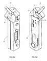
- the structure of the chopper 16 and movement 18 may be appreciated from a consideration of Figs. 3A, 3B and 4. As seen in Figs. 3A and 3B, the movement 18 is enclosed in a housing 50, which may be integrally formed with or alternatively separate from housing 52 of the thermometer (Figs. 2A and 2B).
- the movement 18 typically comprises an axle 54 pivotably mounted on housing 50 and a permanent magnet 56 mounted on axle 54.
- a chopper blade 58, forming the chopper 16, is fixed to axle 54 for reciprocating pivotal movement therewith as illustrated by arrows 60.
- the movement 18 further comprises a coil 62 associated with a core 64.
- the coil 62 receives pulsed inputs at first and second input terminals 66 and 68 from outputs of microprocessor 30 and is operative, in response to the pulsed inputs, to cause magnet 56 and axle 54 to undergo pivotal motion as indicated by arrows 60.
- Typical timing diagrams of the pulse inputs received at terminals 66 and 68 appear in Fig. 4.
- the microprocessor 30 is operative to determine the temperature of the object whose temperature is being measured by employing an ambient temperature input T amb from thermistor 22 via converter 32, which is calibrated by a calibration potentiometer 34 (Fig. 5), and a delta T input from detector 10 via converter 28 which is calibrated by a calibration potentiometer 36.
- the present invention employs a look up table 38 (Fig. 1) containing various values of delta T and T amb which correspond to the inputs to the microprocessor 30.
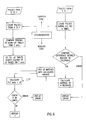
- the operation of the microprocessor 30 is summarized in the software diagram of Fig. 6. Pulses from the converter 32, indicating the ambient temperature are counted using the input from a synchronizing clock 40 (Fig. 5). The look up tables 38 are consulted to obtain T amb .
- delta T is then obtained from look up tables 38 as follows: the pulses received from converter 28 within a predetermined length of time are counted. This operation utilizes the synchronizing clock input from clock 40 and is repeated a plurality of times to produce multiple readings. The differences between the multiple readings are compared to determine if they fit within a predetermined tolerance.
- an error signal is produced. If the multiple readings are within tolerance, an average of the multiple readings is taken and used to access the look up tables 38.
- Look up table 38 contains, in a preferred embodiment of the invention, a series of look up tables for converting the readings from converter 28 to delta T, each for a different ambient temperature. This allows the system to compensate for the variation of the sensitivity of IR detectors as a function of ambient temperature.
- the object temperature may then be calculated by microprocessor 30 as the sum of the ambient temperature and the delta T value.
- the object temperature can be provided directly by appropriate look up tables in look up table 38. If the temperature result is within applicable limits it is displayed at a display 42 (Fig. 1) otherwise an error signal is displayed.
- Figs. 7 and 8A, 8B and 8C illustrate a further embodiment of the present invention for indicating menstrual status, wherein the term "menstrual status" is taken to mean whether ovulation or a possible pregnancy have occurred.
- the clinical thermometer of Fig. 1 additionally comprises a storage unit 70 within which are stored a plurality of temperatures of at least one patient.
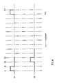
- the stored temperatures as well as the currently measured temperature are analyzed, in accordance with the method shown in Fig. 7, to indicate whether the temperature behavior is typical of ovulation (Fig. 8A), an anovulatory cycle (Fig. 8B) or possible pregnancy (Fig. 8C). If ovulation or pregnancy is indicated, the appropriate information may be displayed on the display 42.
Landscapes
- Physics & Mathematics (AREA)
- General Physics & Mathematics (AREA)
- Spectroscopy & Molecular Physics (AREA)
- Measuring And Recording Apparatus For Diagnosis (AREA)
- Radiation Pyrometers (AREA)
- Yarns And Mechanical Finishing Of Yarns Or Ropes (AREA)
- Electric Clocks (AREA)
Claims (12)
- Temperaturmeßvorrichtung mit:einem IR-Temperaturänderungsdetektor (10) mit einem Detektorausgang;einem Zerhacker (16) mit einem zerhackenden Element, wobei das Element intermittierend den Detektor (10) einem Objekt, dessen Temperatur zu messen ist, aussetzt; undeinem Mittel zum Schaffen einer Anzeige, die die Temperatur des Objekts darstellt in Erwiderung auf die Ausgabe aus dem Detektor, dadurch gekennzeichnet, daßder Zerhacker (16) ein Quarzzeitgeberwerk (18) enthält, das das zerhackende Element ansteuert.
- Temperaturmeßvorrichtung gemäß Anspruch 1, wobei das Quarzzeitgeberwerk (18) ein Drehelement aufweist, und wobei das Drehelement mechanisch mit dem zerhackenden Element verbunden ist zum Antrieb des zerhackenden Elements in hin- und hergehender Bewegung.
- Temperaturmeßvorrichtung gemäß Anspruch 2, wobei die hin- und hergehende Bewegung eine hin- und hergehende Drehbewegung ist.
- Temperaturmeßvorrichtung gemäß Anspruch 2 oder 3 mit einem Mittel zum Begrenzen des Ausmaßes der hin- und hergehenden Bewegung.
- Temperaturmeßvorrichtung gemäß einem der vorhergehenden Ansprüche mit einem Mikroprozessor (30), wobei das Quarzzeitgeberwerk (18) direkt durch den Mikroprozessor (30) angesteuert wird.
- Temperaturmeßvorrichtung gemäß Anspruch 5 mit einem mit dem Mikroprozessor (30) verbundenen Synchronisator, wobei der Mikroprozessor (30) in Verbindung mit dem Synchronisator das Quarzzeitgeberwerk (18) derart steuert, daß ein Aussetzen und Abschirmen des Detektors (10) bei einer im wesentlichen konstanten Geschwindigkeit auftritt.
- Temperaturmeßvorrichtung gemäß einem der vorhergehenden Ansprüche, wobei das Zerhackerelement so wirkt, daß abwechselnd Strahlung von dem Detektor (10) zu dem Detektor (10) reflektiert wird und die Strahlung von dem Objekt auf den Detektor (10) fallen kann.
- Temperaturmeßvorrichtung gemäß einem der vorhergehenden Ansprüche mit:einem Mittel zum Bestimmen der Temperatur des Detektors (10);einem Speicher, in dem empirisch abgeleitete Tabellen gespeichert sind, die die Angabe der Temperatur und die bestimmte Temperatur des Detektors (10) zu der Temperatur des Objekts in Beziehung setzen.
- Temperaturmeßvorrichtung gemäß einem der vorhergehenden Ansprüche mit:
einer Wärmesenke zum Stabilisieren der Temperatur des Detektors (10). - Temperaturmeßvorrichtung gemäß einem der vorhergehenden Ansprüche mit:
einem Berechnungsmittel zum Schaffen einer Ausgabeanzeige des Objekts in Erwiderung auf die Ausgabe des Detektors (10). - Temperaturmeßvorrichtung gemäß einem der vorhergehenden Ansprüche mit einem Mittel zum Analysieren und Anzeigen eines Menstruationsstatus eines Patienten, das auf die Ausgabeanzeige anspricht.
- Temperaturmeßvorrichtung gemäß Anspruch 11, wobei das Mittel zum Analysieren und Anzeigen umfaßt:einen Speicher, der eine Vielzahl von auf den Patienten bezogenen Temperaturen speichert, die über eine Zeitdauer aufgenommen wurden; undein Mittel zum Analysieren der Vielzahl von Temperaturen und Anzeigen eines Menstruationsstatus des Patienten als Ergebnis der Analyse.
Applications Claiming Priority (2)
| Application Number | Priority Date | Filing Date | Title |
|---|---|---|---|
| US890534 | 1992-05-28 | ||
| US07/890,534 US5246292A (en) | 1992-05-28 | 1992-05-28 | Temperature measurement apparatus |
Publications (2)
| Publication Number | Publication Date |
|---|---|
| EP0572095A1 EP0572095A1 (de) | 1993-12-01 |
| EP0572095B1 true EP0572095B1 (de) | 1997-08-13 |
Family
ID=25396808
Family Applications (1)
| Application Number | Title | Priority Date | Filing Date |
|---|---|---|---|
| EP93201522A Expired - Lifetime EP0572095B1 (de) | 1992-05-28 | 1993-05-27 | Vorrichtung zur Temperaturmessung |
Country Status (6)
| Country | Link |
|---|---|
| US (1) | US5246292A (de) |
| EP (1) | EP0572095B1 (de) |
| JP (1) | JPH07280652A (de) |
| AT (1) | ATE156908T1 (de) |
| CA (1) | CA2097039A1 (de) |
| DE (1) | DE69313017T2 (de) |
Families Citing this family (17)
| Publication number | Priority date | Publication date | Assignee | Title |
|---|---|---|---|---|
| US5626147A (en) * | 1993-11-23 | 1997-05-06 | Thermoscan, Inc. | Tympanic thermometer |
| US5717608A (en) * | 1994-09-26 | 1998-02-10 | Luxtron Corporation | Electro-optical board assembly for measuring the temperature of an object surface from infra-red emissions thereof, including an automatic gain control therefore |
| DE19512243A1 (de) * | 1995-03-31 | 1996-10-02 | Raytek Gmbh | Temperaturmeßgerät |
| JPH09257587A (ja) * | 1996-03-26 | 1997-10-03 | Terumo Corp | 非接触型温度計 |
| IL118050A (en) | 1996-04-26 | 2000-07-26 | Katzir Avraham | Infrared-transmitting-fiber-optic-cable-based device for non-contact thermometry |
| IL119956A (en) | 1997-01-01 | 2003-11-23 | Opgal Optronic Ind Ltd | Brake monitoring system and method |
| EP0937971A4 (de) * | 1997-07-28 | 2001-11-07 | Matsushita Electric Industrial Co Ltd | Klinisches strahlungsthermometer |
| EP1077046A4 (de) * | 1998-05-06 | 2002-05-29 | Matsushita Electric Industrial Co Ltd | Ohrthermomether für frauen |
| US6110124A (en) * | 1999-01-14 | 2000-08-29 | Draco Tech International Corp. | Voice thermoscan |
| US6354733B2 (en) * | 1999-01-15 | 2002-03-12 | Ametex, Inc. | System and method for determining combustion temperature using infrared emissions |
| US6422745B1 (en) * | 1999-01-15 | 2002-07-23 | Ametek, Inc. | System and method for determining combustion temperature using infrared emissions |
| US6370486B1 (en) | 1999-01-15 | 2002-04-09 | En'urga Inc. | System and method for determining combustion temperature using infrared emissions |
| US6190329B1 (en) * | 1999-03-19 | 2001-02-20 | Draco Tech International Corp. | Thermoscan having voice and infrared communication interface |
| US20020126137A1 (en) * | 2001-03-06 | 2002-09-12 | Kaestner Frederick G. | Data display device |
| US20070005289A1 (en) * | 2005-06-23 | 2007-01-04 | Fortune Semiconductor Corporation | Temperature compensation apparatus for electronic signal |
| GB0617451D0 (de) * | 2006-09-05 | 2006-10-18 | Medical Prediction Ltd | |
| DE102021114526A1 (de) * | 2021-06-07 | 2022-12-08 | Md Elektronik Gmbh | Erfassungsvorrichtung und Verfahren |
Family Cites Families (37)
| Publication number | Priority date | Publication date | Assignee | Title |
|---|---|---|---|---|
| US2920485A (en) * | 1955-01-11 | 1960-01-12 | Servo Corp Of America | Pyrometer |
| US3091693A (en) * | 1959-09-16 | 1963-05-28 | Barnes Eng Co | Selective radiation detector and free-air thermometer |
| US3293915A (en) * | 1963-08-05 | 1966-12-27 | Barnes Eng Co | Radiometer control means |
| US3463006A (en) * | 1966-09-29 | 1969-08-26 | Air Preheater | Thermal flux gauge |
| US3611806A (en) * | 1969-07-28 | 1971-10-12 | Chino Works Ltd | Radiation thermometer |
| GB1340705A (en) * | 1970-04-28 | 1973-12-12 | Lucas Industries Ltd | Apparatus for temperature measurement |
| CH547487A (de) * | 1972-07-27 | 1974-03-29 | Bbc Brown Boveri & Cie | Verfahren zur beruehrungslosen und materialunabhaengigen temperaturmessung an oberflaechen mittels infrarot-pyrometer. |
| CH557528A (de) * | 1973-04-30 | 1974-12-31 | Bbc Brown Boveri & Cie | Vorrichtung zur beruehrungslosen temperaturmessung an der oberflaeche duenner, langegestreckter objekte. |
| US4005605A (en) * | 1974-07-22 | 1977-02-01 | Mikron Instrument Company, Inc. | Remote reading infrared thermometer |
| IT1041291B (it) * | 1975-08-21 | 1980-01-10 | Raggiotti G | Dispositivo di controllo e indicazione della temperatura corporea |
| US4045670A (en) * | 1976-09-24 | 1977-08-30 | Williamson Corporation | Portable precision radiometer |
| US4072863A (en) * | 1976-10-26 | 1978-02-07 | Roundy Carlos B | Pyroelectric infrared detection system |
| US4148304A (en) * | 1976-11-29 | 1979-04-10 | Bmd Development Trust | Device for measuring ovulation |
| JPS6035018B2 (ja) * | 1979-02-19 | 1985-08-12 | シャープ株式会社 | 婦人体温計 |
| ATE5105T1 (de) * | 1979-06-07 | 1983-11-15 | Bioself International Inc. | Taschenrechner fuer familienplanung. |
| GB2071316B (en) * | 1979-09-12 | 1983-11-09 | Raytek Inc | Hand-held digital temperature measuring instrument |
| US4396020A (en) * | 1979-12-21 | 1983-08-02 | National Research Development Corporation | Measurement of basal body temperature |
| US4375033A (en) * | 1981-03-09 | 1983-02-22 | Bell Telephone Laboratories, Incorporated | Universal detector for atomic and molecular beams |
| US4611153A (en) * | 1983-08-31 | 1986-09-09 | Westinghouse Electric Corp. | Chopper frequency determination apparatus |
| GB8415164D0 (en) * | 1984-06-14 | 1984-07-18 | Beta Instr Co | Measuring temperature of object |
| US4602642A (en) * | 1984-10-23 | 1986-07-29 | Intelligent Medical Systems, Inc. | Method and apparatus for measuring internal body temperature utilizing infrared emissions |
| US4790324A (en) * | 1984-10-23 | 1988-12-13 | Intelligent Medical Systems, Inc. | Method and apparatus for measuring internal body temperature utilizing infrared emissions |
| US4743122A (en) * | 1984-12-24 | 1988-05-10 | Sanyo Electric Co., Ltd. | Infrared-ray temperature measuring apparatus |
| DE3650723T2 (de) * | 1985-04-17 | 2000-03-16 | Thermoscan Inc. | Elektronisches infrarot-thermometer und temperaturmessung |
| US4784149A (en) * | 1986-01-13 | 1988-11-15 | Optical Sensors, Inc. | Infrared thermometer with automatic calibration |
| GB2186977A (en) * | 1986-02-25 | 1987-08-26 | Benytone Corp | Fertility indicating thermometer |
| DE3750278D1 (de) * | 1986-06-20 | 1994-09-01 | Lehmann Martin | Verfahren zum berührungslosen Messen einer Temperatur von einem Körper sowie Anordnung hierfür. |
| US5001657A (en) * | 1986-06-24 | 1991-03-19 | Minolta Camera Kabushiki Kaisha | Radiation thermometer |
| GB8706507D0 (en) * | 1987-03-19 | 1987-04-23 | Land Infrared Ltd | Radiation thermometer |
| EP0411121A4 (en) * | 1987-12-25 | 1991-05-15 | Nippon Steel Corporation | Optical thermometer |
| US4907895A (en) * | 1988-03-31 | 1990-03-13 | Ivac Corporation | Optical chopper for infrared thermometer |
| JP2826337B2 (ja) * | 1988-04-12 | 1998-11-18 | シチズン時計株式会社 | 放射体温計 |
| US5018872A (en) * | 1988-11-01 | 1991-05-28 | Diatek, Inc. | Probe assembly for infrared thermometer |
| DE3838123A1 (de) * | 1988-11-10 | 1990-05-17 | Bosch Gmbh Robert | Waermestrahlungssensor mit einem pyroelektrischen aufnahmeelement |
| GB2235042B (en) * | 1989-07-29 | 1993-10-27 | Smiths Industries Plc | Sensing systems |
| JPH03133440A (ja) * | 1989-10-18 | 1991-06-06 | Nishitomo:Kk | 婦人用体温計 |
| US5157684A (en) * | 1991-10-23 | 1992-10-20 | United Technologies Corporation | Optically pulsed laser |
-
1992
- 1992-05-28 US US07/890,534 patent/US5246292A/en not_active Expired - Fee Related
-
1993
- 1993-05-26 CA CA002097039A patent/CA2097039A1/en not_active Abandoned
- 1993-05-27 DE DE69313017T patent/DE69313017T2/de not_active Expired - Fee Related
- 1993-05-27 EP EP93201522A patent/EP0572095B1/de not_active Expired - Lifetime
- 1993-05-27 AT AT93201522T patent/ATE156908T1/de not_active IP Right Cessation
- 1993-05-28 JP JP5127317A patent/JPH07280652A/ja active Pending
Also Published As
| Publication number | Publication date |
|---|---|
| DE69313017T2 (de) | 1998-03-12 |
| JPH07280652A (ja) | 1995-10-27 |
| ATE156908T1 (de) | 1997-08-15 |
| DE69313017D1 (de) | 1997-09-18 |
| CA2097039A1 (en) | 1993-11-29 |
| US5246292A (en) | 1993-09-21 |
| EP0572095A1 (de) | 1993-12-01 |
Similar Documents
| Publication | Publication Date | Title |
|---|---|---|
| EP0572095B1 (de) | Vorrichtung zur Temperaturmessung | |
| CA2098313C (en) | Infrared thermometer utilizing calibration mapping | |
| US5653238A (en) | Radiation detector probe | |
| CA2012528C (en) | Infrared thermometry system and method | |
| US6195581B1 (en) | Process for evaluating the signal of an infrared thermometer, and infrared thermometer | |
| EP0777114B1 (de) | Klinisches Strahlungsthermometer | |
| US5017018A (en) | Clinical thermometer | |
| US4907895A (en) | Optical chopper for infrared thermometer | |
| US6219573B1 (en) | Radiation detector probe | |
| US4602642A (en) | Method and apparatus for measuring internal body temperature utilizing infrared emissions | |
| EP0219531B1 (de) | Elektronisches infrarot-thermometer und temperaturmessung | |
| JPH0741026B2 (ja) | 体温計 | |
| GB2262804A (en) | Laser power meter | |
| JP2799290B2 (ja) | ポケットサイズのレーザーパワーメーター | |
| US3604266A (en) | Temperature measuring apparatus | |
| WO1986001595A1 (en) | Improvements in or relating to thermometers | |
| US5139331A (en) | Radiometer including means for alternately measuring both power and energy with one pyroelectric detector | |
| JP2993106B2 (ja) | 非接触口腔用体温計 | |
| JP2993103B2 (ja) | 非接触口腔用体温計 | |
| SU1753305A1 (ru) | Устройство дл измерени температуры | |
| JPH0536056B2 (de) | ||
| JP3455922B2 (ja) | 放射体温計 | |
| JPH0271124A (ja) | 光温度計 | |
| JPS6219728A (ja) | 放射温度計 | |
| Cascetta | Experimental intercomparison of medical thermometers |
Legal Events
| Date | Code | Title | Description |
|---|---|---|---|
| PUAI | Public reference made under article 153(3) epc to a published international application that has entered the european phase |
Free format text: ORIGINAL CODE: 0009012 |
|
| AK | Designated contracting states |
Kind code of ref document: A1 Designated state(s): AT BE CH DE DK ES FR GB GR IE IT LI LU MC NL PT SE |
|
| RIN1 | Information on inventor provided before grant (corrected) |
Inventor name: GERLITZ,YONATAN Inventor name: MORAN,DAN Inventor name: GAL, ELI |
|
| 17P | Request for examination filed |
Effective date: 19940526 |
|
| 17Q | First examination report despatched |
Effective date: 19950927 |
|
| GRAG | Despatch of communication of intention to grant |
Free format text: ORIGINAL CODE: EPIDOS AGRA |
|
| GRAH | Despatch of communication of intention to grant a patent |
Free format text: ORIGINAL CODE: EPIDOS IGRA |
|
| RAP1 | Party data changed (applicant data changed or rights of an application transferred) |
Owner name: SAAT LTD. |
|
| GRAH | Despatch of communication of intention to grant a patent |
Free format text: ORIGINAL CODE: EPIDOS IGRA |
|
| GRAA | (expected) grant |
Free format text: ORIGINAL CODE: 0009210 |
|
| AK | Designated contracting states |
Kind code of ref document: B1 Designated state(s): AT BE CH DE DK ES FR GB GR IE IT LI LU MC NL PT SE |
|
| PG25 | Lapsed in a contracting state [announced via postgrant information from national office to epo] |
Ref country code: LI Free format text: LAPSE BECAUSE OF FAILURE TO SUBMIT A TRANSLATION OF THE DESCRIPTION OR TO PAY THE FEE WITHIN THE PRESCRIBED TIME-LIMIT Effective date: 19970813 Ref country code: GR Free format text: LAPSE BECAUSE OF FAILURE TO SUBMIT A TRANSLATION OF THE DESCRIPTION OR TO PAY THE FEE WITHIN THE PRESCRIBED TIME-LIMIT Effective date: 19970813 Ref country code: ES Free format text: THE PATENT HAS BEEN ANNULLED BY A DECISION OF A NATIONAL AUTHORITY Effective date: 19970813 Ref country code: DK Free format text: LAPSE BECAUSE OF NON-PAYMENT OF DUE FEES Effective date: 19970813 Ref country code: CH Free format text: LAPSE BECAUSE OF FAILURE TO SUBMIT A TRANSLATION OF THE DESCRIPTION OR TO PAY THE FEE WITHIN THE PRESCRIBED TIME-LIMIT Effective date: 19970813 Ref country code: BE Effective date: 19970813 Ref country code: AT Effective date: 19970813 |
|
| REF | Corresponds to: |
Ref document number: 156908 Country of ref document: AT Date of ref document: 19970815 Kind code of ref document: T |
|
| REG | Reference to a national code |
Ref country code: CH Ref legal event code: EP |
|
| REF | Corresponds to: |
Ref document number: 69313017 Country of ref document: DE Date of ref document: 19970918 |
|
| ITF | It: translation for a ep patent filed | ||
| PG25 | Lapsed in a contracting state [announced via postgrant information from national office to epo] |
Ref country code: SE Effective date: 19971113 |
|
| PG25 | Lapsed in a contracting state [announced via postgrant information from national office to epo] |
Ref country code: PT Effective date: 19971114 |
|
| ET | Fr: translation filed | ||
| REG | Reference to a national code |
Ref country code: CH Ref legal event code: PL |
|
| PGFP | Annual fee paid to national office [announced via postgrant information from national office to epo] |
Ref country code: FR Payment date: 19980526 Year of fee payment: 6 |
|
| PG25 | Lapsed in a contracting state [announced via postgrant information from national office to epo] |
Ref country code: LU Free format text: LAPSE BECAUSE OF NON-PAYMENT OF DUE FEES Effective date: 19980527 Ref country code: IE Free format text: LAPSE BECAUSE OF NON-PAYMENT OF DUE FEES Effective date: 19980527 Ref country code: GB Free format text: LAPSE BECAUSE OF NON-PAYMENT OF DUE FEES Effective date: 19980527 |
|
| PGFP | Annual fee paid to national office [announced via postgrant information from national office to epo] |
Ref country code: NL Payment date: 19980531 Year of fee payment: 6 |
|
| PGFP | Annual fee paid to national office [announced via postgrant information from national office to epo] |
Ref country code: DE Payment date: 19980610 Year of fee payment: 6 |
|
| PLBE | No opposition filed within time limit |
Free format text: ORIGINAL CODE: 0009261 |
|
| STAA | Information on the status of an ep patent application or granted ep patent |
Free format text: STATUS: NO OPPOSITION FILED WITHIN TIME LIMIT |
|
| 26N | No opposition filed | ||
| PG25 | Lapsed in a contracting state [announced via postgrant information from national office to epo] |
Ref country code: MC Free format text: LAPSE BECAUSE OF NON-PAYMENT OF DUE FEES Effective date: 19981130 |
|
| GBPC | Gb: european patent ceased through non-payment of renewal fee |
Effective date: 19980527 |
|
| PG25 | Lapsed in a contracting state [announced via postgrant information from national office to epo] |
Ref country code: NL Free format text: LAPSE BECAUSE OF NON-PAYMENT OF DUE FEES Effective date: 19991201 |
|
| PG25 | Lapsed in a contracting state [announced via postgrant information from national office to epo] |
Ref country code: FR Free format text: LAPSE BECAUSE OF NON-PAYMENT OF DUE FEES Effective date: 20000131 |
|
| NLV4 | Nl: lapsed or anulled due to non-payment of the annual fee |
Effective date: 19991201 |
|
| PG25 | Lapsed in a contracting state [announced via postgrant information from national office to epo] |
Ref country code: DE Free format text: LAPSE BECAUSE OF NON-PAYMENT OF DUE FEES Effective date: 20000301 |
|
| REG | Reference to a national code |
Ref country code: FR Ref legal event code: ST |
|
| PG25 | Lapsed in a contracting state [announced via postgrant information from national office to epo] |
Ref country code: IT Free format text: LAPSE BECAUSE OF NON-PAYMENT OF DUE FEES Effective date: 20050527 |