EP0572162A2 - Sense FET et amplificateur rapide - Google Patents
Sense FET et amplificateur rapide Download PDFInfo
- Publication number
- EP0572162A2 EP0572162A2 EP93303875A EP93303875A EP0572162A2 EP 0572162 A2 EP0572162 A2 EP 0572162A2 EP 93303875 A EP93303875 A EP 93303875A EP 93303875 A EP93303875 A EP 93303875A EP 0572162 A2 EP0572162 A2 EP 0572162A2
- Authority
- EP
- European Patent Office
- Prior art keywords
- sense
- current
- circuit
- voltage
- output
- Prior art date
- Legal status (The legal status is an assumption and is not a legal conclusion. Google has not performed a legal analysis and makes no representation as to the accuracy of the status listed.)
- Granted
Links
Images

Classifications
-
- H—ELECTRICITY
- H02—GENERATION; CONVERSION OR DISTRIBUTION OF ELECTRIC POWER
- H02P—CONTROL OR REGULATION OF ELECTRIC MOTORS, ELECTRIC GENERATORS OR DYNAMO-ELECTRIC CONVERTERS; CONTROLLING TRANSFORMERS, REACTORS OR CHOKE COILS
- H02P6/00—Arrangements for controlling synchronous motors or other dynamo-electric motors using electronic commutation dependent on the rotor position; Electronic commutators therefor
- H02P6/28—Arrangements for controlling current
-
- H—ELECTRICITY
- H02—GENERATION; CONVERSION OR DISTRIBUTION OF ELECTRIC POWER
- H02P—CONTROL OR REGULATION OF ELECTRIC MOTORS, ELECTRIC GENERATORS OR DYNAMO-ELECTRIC CONVERTERS; CONTROLLING TRANSFORMERS, REACTORS OR CHOKE COILS
- H02P6/00—Arrangements for controlling synchronous motors or other dynamo-electric motors using electronic commutation dependent on the rotor position; Electronic commutators therefor
- H02P6/08—Arrangements for controlling the speed or torque of a single motor
-
- H—ELECTRICITY
- H02—GENERATION; CONVERSION OR DISTRIBUTION OF ELECTRIC POWER
- H02P—CONTROL OR REGULATION OF ELECTRIC MOTORS, ELECTRIC GENERATORS OR DYNAMO-ELECTRIC CONVERTERS; CONTROLLING TRANSFORMERS, REACTORS OR CHOKE COILS
- H02P7/00—Arrangements for regulating or controlling the speed or torque of electric DC motors
- H02P7/03—Arrangements for regulating or controlling the speed or torque of electric DC motors for controlling the direction of rotation of DC motors
- H02P7/04—Arrangements for regulating or controlling the speed or torque of electric DC motors for controlling the direction of rotation of DC motors by means of a H-bridge circuit
-
- H—ELECTRICITY
- H03—ELECTRONIC CIRCUITRY
- H03K—PULSE TECHNIQUE
- H03K2217/00—Indexing scheme related to electronic switching or gating, i.e. not by contact-making or -breaking covered by H03K17/00
- H03K2217/0027—Measuring means of, e.g. currents through or voltages across the switch
Definitions
- This invention relates to improvements in circuitry for sensing and amplifying electronic signals, and more particularly to a circuit that uses a sensefet to sense the current flowing through the stator coil of a polyphase motor and a fast amplifier for amplifying the sensefet output voltage, and still more particularly to improvements in motor driver circuits for polyphase dc motors.
- the present invention is potentially useful for a variety of current-sensing applications, it finds particular application in the operation of three-phase dc motors of the type typically used in computer-related applications.
- These computer applications include hard disk drives, CD ROM drives, floppy disks, and the like, in which three phase brushless, sensorless dc motors are becoming more popular, principally due to their reliability, low weight, and accuracy.
- a transconductance loop is usually used in the driver stage to obtain good regulation. Therefore, a need exists to measure accurately the current through each coil of a polyphase motor.
- sensefet a field-effect transistor designed for current sensing, particularly with high power loads.
- a sensefet typically presents an output, called “sense,” that provides a current proportional to the current in the main device.
- sensefet approach is used to monitor current on a power conductor, it may be important for the particular application to have a very fast amplifier to convert the "sense" current into a voltage signal for further processing.
- amplifier speed is important when the amplified voltage signal is used as feedback for a motor control loop. In motor control loops, an appreciable delay in the signal may cause a significant error in the output of the loop.
- What is needed is a circuit that will quickly respond to the input voltage presented on the output of an N-channel D-MOS FET or similar device when that device is used as a "high-side" driver (i.e., one that sources current to the load).
- the output voltage is generally available on a resistor connected to a reference potential or to the lower supply rail.
- the amplifier should have an input common mode voltage range compatible with (i.e., greater than) the supply voltage, to prevent saturation of the input stage.
- the amplifier should be a single-gain-stage amplifier. Therefore, no compensation capacitors are required and the device can be easily and inexpensively integrated onto an integrated circuit device. Also, it should be easy to connect the amplifier in parallel with other amplifiers of the same type. In this way, the current can be sensed on multiple stages and summed, giving a measure of the total current drawn by the stator coils at any particular time.
- a circuit for providing drive current to a coil of a motor includes a sensefet current sensing device connected to sense current delivered to the coil and to output a "sense" current proportional to the current delivered to the load.
- An amplifier is connected to impose, when the feedback loop is closed, the voltage at the load output onto the "sense" terminal.
- a pass transistor is connected to route the "sense" current to an output node.
- the circuit provides an output voltage suitable for use as feedback signal in a motor control system.
- Figure 1 is an electrical schematic diagram of a portion of a motor driver circuit incorporating a sensefet, as a high-side motor driver, and a fast amplifier, according to a preferred embodiment of the invention.
- Figure 2 is a simplified electrical schematic block diagram of an equivalent circuit for the preferred embodiment of the invention of Figure 1.
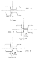
- Figure 3 is an electronic signal diagram plotting the input signal to the amplifier with the output signal from the amplifier for the condition in which the input to the amplifier (i.e., V SOURCE , the voltage on the source of the device) is less than the supply voltage V CC .
- Figure 4 is an electronic signal diagram also showing the amplifier input and output signals for an overdrive input voltage (V SOURCE ) 0.4 volts greater than the supply voltage.
- V SOURCE overdrive input voltage
- Figure 5 is an electronic signal diagram also showing the input and output voltages of the amplifier for an overdrive input voltage (V SOURCE ) 2.0 volts greater than the supply voltage.
- V SOURCE overdrive input voltage
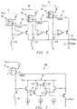
- Figure 6 is an electronic schematic diagram of a system of multiple sensefets and fast-amplifiers in which a plurality of fast-amplifiers are connected onto a single output, used for sensing the current through multiple conductors and presenting an output voltage representing the sum of the currents sensed.
- Figure 7 is an electrical schematic diagram of another embodiment of a sensefet and fast amplifier circuit including additional components forming current-mirroring circuitry in the differential stage to alter circuit performance.
- FIG. 1 An electrical schematic of a sensefet and fast amplifier circuit 10 according to a preferred embodiment of the invention is shown in Figure 1.
- a sensefet is a modified FET optimized for a current sensing role, an example of which is a device type MTP10N10M distributed by Motorola; however, many different sensefet-type devices can be employed in this capacity.
- the circuit 10 can be constructed of discrete components, preferably, it is integrated onto a single semiconductor chip that can be adapted for connection to a stator coil of a three-phase dc motor. Such motor can be preferably used, for example, in systems such as computer hard disk drives, CD ROM drives, floppy disk drives, and the like.
- Such motors typically have a plurality of stator coils, and the need often arises to monitor the current flow at a particular time through some or all the stator coils.
- current information may be used as a feedback signal for a current control loop.
- a sensefet device on a conductor carrying the current to be monitored detects this current information.
- Such sensefet device provides an output "sense" current on a "sense” terminal that is proportional to the current flowing through the power device. To maximize the accuracy of proportionality, the "sense" terminal should be held at the same potential as the source terminal.
- a sensefet When using a sensefet to monitor current on a power conductor, it may be necessary that the response of the circuit be fast for further processing. Such speed may be important, for instance, when the "sense" current is to be used as a feedback signal in a control loop, such as a motor speed-control loop. In speed control loops, a significant time delay in the signal may introduce an unacceptable error into the output of the feedback loop.
- the circuit 10 of Figure 1 extracts current information from the "sense" output 21 of an N-channel D-MOS sensefet 14 or a similar device, with the sensefet 14 used as a "high-side” driver (i.e., it sources current to the load).
- the sensefet 14 is used as such a high-side driver, it is important that the amplifier 11 have an input common-mode voltage range compatible with the positive supply (i.e., greater than the supply potential).
- the drain terminal 13 of the sensefet 14 is connected on line 12 to V CC , and carries current for delivery to the stator coil 16.
- the gate terminal 15 is connected to a predriver circuit (not shown), and the "sense" output terminal 21 on which the "sense” current flows is connected to the input line 18 of the fast amplifier 11.
- the source terminal 19 is connected to the conductor 20 that provides a second input to the amplifier 11 and carries current to the stator coil 16 of the motor.
- the Kelvin source contact terminal 17, when available, can be connected to the second input of the amplifier instead, to maximize accuracy.
- the sensefet 14 thus serves to sense the current through the conductor 12.
- the predriver circuit connected to the gate terminal 15 drives the sensefet 14 into full conduction, or low impedance, so that the current flows through the drain and the source to power the stator coil 16.
- the "sense" output 21 of the sensefet 14 is a “sense” current that is proportional to the amount of current flowing through the "power" source terminal 19.
- the "sense" output terminal 21 of the sensefet 14 presents the V SOURCE , signal to the input line 18 of the fast amplifier 10 for amplification.
- Connected to the input line 18 is a first end of a resistor 42.
- the other end of the resistor 42 is connected to the base of an NPN transistor 38.
- the collector of the transistor 38 is connected to V CC , and the emitter is connected to a current source 40 that is connected to a reference potential 27.
- a differential amplifier 34 is formed by two NPN transistors 32 and 28, the collector of the transistor 32 being connected to a current source 30 that is connected to V CC .
- the collector of the NPN transistor 28 is connected directly to V CC .
- the emitters of both of the transistors 32 and 28 are connected to a current source 36, which is connected to the reference potential 27.
- the base of the NPN transistor 28 is connected to the emitter of another NPN transistor 24.
- the transistor 24 has its collector connected to V CC and its emitter connected to a current source 26 that is connected to the reference potential 27.
- the current sources 30, 26, 36, and 40 are typical internal components of operational amplifiers, as known in the art, for generating biasing currents necessary for the operation of the circuit.
- a resistor 22 has a first end connected to the base of the NPN transistor 24 and a second end to the source terminal 19 of the sensefet 14.
- one end of a resistor 44 is connected to the input line 18 of the fast amplifier 11 and other end is connected to the emitter of an output PNP transistor 46.
- the transistor 46 has its base connected to the collector of the NPN transistor 32 and its collector connected to a first end of a sense resistor, R SENSE 50.
- the sense resistor 50 has its other end connected to the reference potential 27.
- the output terminal 49 at which the output voltage (V OUT ) appears is connected to R SENSE 50 and the collector of the transistor 46.
- FIG. 2 An equivalent schematic for the circuit of Figure 1 is shown in Figure 2.
- the portion of the fast amplifier 11 exclusive of the output PNP transistor 46, the sense resistor 50, resistor 44, and the output terminal 49 is replaced by an operational amplifier 35.
- the inverting input of the operational amplifier 35 is connected to the "sense" output terminal 21 of the sensefet 14, and the non-inverting input is connected to the source terminal 19 of the sensefet 14 and to the stator coil 16.
- the output of the operational amplifier 35 is connected to the base of the pass PNP transistor 46.
- the pass transistor 46 has its emitter connected to the "sense" output terminal 21 of the sensefet 14 through the resistor 44.
- the collector of the pass transistor 46 is connected to the output terminal 49 and one end of R SENSE 50.
- the other end of R SENSE 50 is connected to the reference potential 27.
- the fast amplifier 11 has a good response to input voltages (V SOURCE ) greater than V CC .
- the response of the fast amplifier 11 to various voltage conditions is shown in Figures 4, 5, and 6.
- Figure 3 shows the results in which the input voltage (V SOURCE ) is always lower than V CC , which would be the normal operating condition for most amplifiers.
- the output waveform, V OUT of the fast amplifier 11 closely tracks the input waveform V IN (i.e., V SOURCE , from the sensefet 14) with a rise time of about 300ns.
- the V OUT waveform is inverted with respect to the input waveform.
- the time scale of the particular waveforms is 500 nanoseconds per division.
- the x-axis is not necessarily a zero voltage level.
- the drawing shows the way the two signals are simultaneously displayed on the oscilloscope.
- Figure 4 shows the circuit response, or recovery from overload, when V SOURCE jumps down from 0.4 volts above V CC .
- the output signal, V OUT does not track the input signal V IN as closely as it was in Figure 1. In this case there is a greater time delay (about 500 ns) in changing states.
- the V OUT waveform is an inversion of the V IN waveform.
- the horizontal divisions are 500 nanoseconds.
- the x-axis is not necessarily a zero voltage level.
- Figure 5 shows the circuit response in which V SOURCE recovers from exceeding the voltage supply by 2.0 volts, and in which there is again a time delay (around 500 nanoseconds).
- the horizontal divisions are 500 nanoseconds.
- the V OUT waveform is inverted with respect to the V IN waveform, and again the x-axis is not necessarily a zero voltage level.
- the amplifier 11 has its inputs compatible with operation at or above the positive supply. It has a fast recovery from voltages above the supply, which is useful for inductive loads (i.e., stator coils) due to possible over-voltages due to current recirculation.
- the circuit is very fast and has a well behaved response due to a single-gain-stage design in which all the active components in the signal path are NPN transistors, except the output PNP transistor. It does not require any compensation capacitors due to the single-gain-stage architecture and uses only a few components.
- the circuit therefore may be easily and cheaply integrated onto an integrated circuit device.
- resistors 22, 42, and 44 in the circuit can be of zero value; i.e., the resistors can be removed without affecting the operation of the circuit. Their presence in the embodiment illustrated is favored mostly due to reliability considerations in some environments.
- the precision of the circuit 10 is better than 1% due to the relatively high open-loop gain, which may be in excess of 50 db with a standard bipolar technology.
- An added feature of the invention is the ease of placing the outputs of multiple sensing amplifiers onto a single resistor. This is because the outputs are provided on the collectors of the pass PNP transistor of each device. This embodiment is shown in Figure 6.
- Three fast amplifiers 68, 70, and 72, receive their respective V SOURCE signals from their respective sensefets 56, 58, and 60. Each sensefet 56, 58, and 60 senses the current through respective three different conductors 57, 59, and 61.
- the three fast amplifiers 56, 58, and 60 have their outputs placed onto a single resistor R SENSE 77, to give a single output.
- the sensefets 57, 59, and 61 are connected to their respective amplifiers 68, 70, and 72, their respective conductors 57, 59, and 61, and their respective stator coils 102, 104, and 106 in the same way as the sensefet 14 is connected to its various connections in Figure 1. While the use of three such amplifiers may be typical, since many motors have three phases, the idea is not intended to be limited to the use of three fast amplifiers, and as many may be used as required.
- the embodiment of Figure 6 In applications such as multi-phase motor operation, the embodiment of Figure 6 generates a V OUT signal on the terminal 76 of the sense resistor 77.
- the V OUT signal is proportional to the sum of the currents sensed in the different stator coils 102, 104, and 106. This is indicative of the total current drawn by the motor.
- Figure 7 shows another embodiment of a sensefet and fast amplifier circuit 109 in which the differential state includes current-mirroring circuitry 116. Except the absence of the current generator and the addition of a current mirror circuit, as discussed below, the circuit of Figure 7 is similar to the Figure 1 circuit embodiment.
- a PNP current-mirror circuit 116 having PNP transistors 118 and 120 has been added to the circuit of the Figure 1 embodiment.
- the emitter of PNP transistor 120 is connected to V CC , and the collector is connected to the collector of the NPN transistor 32.
- the transistor 118 has its emitter connected to V CC and its collector connected to the collector of the NPN transistor 28.
- the base of the PNP transistor 118 is connected to the base of the PNP transistor 120 and to the collector of the PNP transistor 118.
- Figure 7 embodiment has lower offsets in the differential amplifier 34 than the circuit of Figure 1, it may not provide the dynamic performance of the Figure 1 embodiment. This is because when low performance lateral PNP transistors are used the PNP current mirror 116 creates a greater phase shift, degrading the phase margin and stability.
- a compensation network as known in the art, may be employed to alter the frequency response accordingly.
- the circuit shown may be also applied for current sensing when other power transistors and drivers are used, so that p-channel devices and bipolar structures may be adopted instead of sensefet transistor 14. Also, two resistors connected on one side to V CC and on the other side, respectively, to terminals 19 and 21 may be substituted for the sensefet 14, still preserving the functionality of the current sensing amplifier.
Landscapes
- Engineering & Computer Science (AREA)
- Power Engineering (AREA)
- Control Of Motors That Do Not Use Commutators (AREA)
- Measurement Of Current Or Voltage (AREA)
Applications Claiming Priority (2)
| Application Number | Priority Date | Filing Date | Title |
|---|---|---|---|
| US07/890,945 US5374857A (en) | 1992-05-29 | 1992-05-29 | Circuit for providing drive current to a motor using a sensefet current sensing device and a fast amplifier |
| US890945 | 1992-05-29 |
Publications (3)
| Publication Number | Publication Date |
|---|---|
| EP0572162A2 true EP0572162A2 (fr) | 1993-12-01 |
| EP0572162A3 EP0572162A3 (en) | 1994-07-20 |
| EP0572162B1 EP0572162B1 (fr) | 1997-04-16 |
Family
ID=25397372
Family Applications (1)
| Application Number | Title | Priority Date | Filing Date |
|---|---|---|---|
| EP93303875A Expired - Lifetime EP0572162B1 (fr) | 1992-05-29 | 1993-05-19 | Sense FET et amplificateur rapide |
Country Status (4)
| Country | Link |
|---|---|
| US (1) | US5374857A (fr) |
| EP (1) | EP0572162B1 (fr) |
| JP (1) | JPH06189583A (fr) |
| DE (1) | DE69309776T2 (fr) |
Cited By (6)
| Publication number | Priority date | Publication date | Assignee | Title |
|---|---|---|---|---|
| EP0831578A3 (fr) * | 1996-09-20 | 1998-09-23 | Texas Instruments Incorporated | Réaction de courant pour moteurs polyphasés à courant continu |
| EP0890844A3 (fr) * | 1997-07-12 | 2000-07-19 | Mannesmann VDO Aktiengesellschaft | Circuit pour suivre un courant de charge |
| WO2004030173A1 (fr) * | 2002-09-26 | 2004-04-08 | Robert Bosch Gmbh | Procede pour detecter un courant de surcharge d'un entrainement electrique |
| FR2853468A1 (fr) * | 2003-04-01 | 2004-10-08 | Siemens Ag | Circuit de detection pour convertisseur a courant continu |
| EP1223654A3 (fr) * | 2000-12-29 | 2005-01-12 | Nokia Corporation | Circuit pour charger une batterie |
| WO2005076456A1 (fr) * | 2004-02-03 | 2005-08-18 | Ebm-Papst St. Georgen Gmbh & Co. Kg | Moteur a commutation electronique, et procede pour le commander |
Families Citing this family (27)
| Publication number | Priority date | Publication date | Assignee | Title |
|---|---|---|---|---|
| US5500619A (en) * | 1992-03-18 | 1996-03-19 | Fuji Electric Co., Ltd. | Semiconductor device |
| GB9413684D0 (en) * | 1994-07-07 | 1994-08-24 | Lucas Ind Plc | Drive circuit |
| DE69627909T2 (de) | 1995-01-17 | 2003-11-13 | Vlt Corp | Regelung der in den Transformatoren von Schaltnetzteilen gepseicherten Energie |
| EP0743529B1 (fr) * | 1995-05-16 | 2004-07-28 | STMicroelectronics S.r.l. | Procédé et circuit correspondant pour la détection d'une charge ouverte |
| US5689162A (en) * | 1995-06-07 | 1997-11-18 | Sgs-Thomson Microelectronics, Inc. | Apparatus and method for current sensing for motor driver in pwm mode |
| US5723963A (en) * | 1995-06-07 | 1998-03-03 | Sgs-Thomson Microelectronics, Inc. | Apparatus and method for controlling transition between PWM and linear operation of a motor |
| US5675268A (en) * | 1995-10-03 | 1997-10-07 | Motorola, Inc. | Overcurrent detection circuit for a power MOSFET and method therefor |
| JPH1084266A (ja) * | 1996-09-10 | 1998-03-31 | Mitsubishi Electric Corp | 電流切替回路 |
| US5825218A (en) * | 1996-10-24 | 1998-10-20 | Stmicroelectronics, Inc. | Driver circuit including slew rate control system with improved voltage ramp generator |
| US5742193A (en) * | 1996-10-24 | 1998-04-21 | Sgs-Thomson Microelectronics, Inc. | Driver circuit including preslewing circuit for improved slew rate control |
| US5828245A (en) * | 1996-10-24 | 1998-10-27 | Stmicroelectronics, Inc. | Driver circuit including amplifier operated in a switching mode |
| US5883479A (en) * | 1997-07-01 | 1999-03-16 | Stmicroelectronics, Inc. | BEMF rectification during power off to prevent parasitic effect |
| US6282107B1 (en) * | 2000-03-07 | 2001-08-28 | Vlt Corporation | Integrated sense and switch circuitry for transformer core resetting |
| US6586980B1 (en) | 2000-03-31 | 2003-07-01 | Stmicroelectronics, Inc. | Driver circuit having a slew rate control system with improved linear ramp generator including ground |
| US6317000B1 (en) | 2000-10-05 | 2001-11-13 | Texas Instruments Incorporated | Overload recovery circuit and method |
| GB0110634D0 (en) * | 2001-05-01 | 2001-06-20 | Gunton Bruce S | Monitoring apparatus |
| DE10154763A1 (de) * | 2001-11-09 | 2003-05-22 | Continental Teves Ag & Co Ohg | Verfahren und Schaltungsanordnung zur Erkennung eines Defekts von Halbleiterschaltelementen und deren Verwendung in elektronischen Bremskraft- und Fahrdynamikreglern |
| US6703900B2 (en) | 2002-06-05 | 2004-03-09 | Texas Instruments Incorporated | Fast, stable overload recovery circuit and method |
| US6900672B2 (en) * | 2003-03-28 | 2005-05-31 | Stmicroelectronics, Inc. | Driver circuit having a slew rate control system with improved linear ramp generator including ground |
| US7005881B2 (en) * | 2003-05-14 | 2006-02-28 | International Rectifier Corporation | Current sensing for power MOSFET operable in linear and saturated regions |
| US8749183B2 (en) | 2008-09-02 | 2014-06-10 | Stmicroelectronics, Inc. | Determining a position of a motor using an on-chip component |
| US7852148B2 (en) * | 2009-03-27 | 2010-12-14 | Semiconductor Components Industries, Llc | Method of forming a sensing circuit and structure therefor |
| US9998042B2 (en) | 2013-03-04 | 2018-06-12 | Seagate Technology Llc | Torque disturbance cancellation for a motor |
| EP2843496A1 (fr) * | 2013-08-30 | 2015-03-04 | Nxp B.V. | Circuit de commande de courant avec transistors à effet de champ à detection de courant en parallel |
| CN104977450B (zh) | 2014-04-03 | 2019-04-30 | 深圳市中兴微电子技术有限公司 | 一种电流采样电路及方法 |
| JP6489031B2 (ja) * | 2016-01-27 | 2019-03-27 | 株式会社デンソー | モータ制御装置 |
| DE102024204780B3 (de) | 2024-05-23 | 2025-06-05 | Infineon Technologies Austria Ag | Gehäuse mit einem Funktionschip und mit einem physikalisch getrennten Erfassungschip und Verfahren zum Herstellen |
Family Cites Families (14)
| Publication number | Priority date | Publication date | Assignee | Title |
|---|---|---|---|---|
| EP0139078B1 (fr) * | 1980-06-24 | 1989-01-25 | Nec Corporation | Circuit amplificateur à transistor |
| US4675561A (en) * | 1985-11-15 | 1987-06-23 | Precision Monolithics, Inc. | FET output drive circuit with parasitic transistor inhibition |
| NL8503394A (nl) * | 1985-12-10 | 1987-07-01 | Philips Nv | Stroomaftastschakeling voor een vermogenshalfgeleiderinrichting, in het bijzonder geintegreerde intelligente vermogenshalfgeleiderschakelaar voor met name automobieltoepassingen. |
| US4667121A (en) * | 1986-05-27 | 1987-05-19 | Motorola, Inc. | Integrated circuit speed controller |
| US4654568A (en) * | 1986-08-21 | 1987-03-31 | Motorola, Inc. | MOSFET "H" switch with current sensing |
| GB2206010A (en) * | 1987-06-08 | 1988-12-21 | Philips Electronic Associated | Differential amplifier and current sensing circuit including such an amplifier |
| FR2628217B1 (fr) * | 1988-03-07 | 1990-07-27 | Sgs Thomson Microelectronics | Circuit de mesure d'un courant |
| US4937469A (en) * | 1988-08-30 | 1990-06-26 | International Business Machines Corporation | Switched current mode driver in CMOS with short circuit protection |
| US5032745A (en) * | 1989-02-22 | 1991-07-16 | National Semiconductor Corporation | Current sensing of DC or a stepper motor |
| DE69026525T2 (de) * | 1989-05-09 | 1996-09-12 | United Technologies Automotive | Schaltung zur Leistungsabgabe mit Stromerfassung |
| US5061863A (en) * | 1989-05-16 | 1991-10-29 | Kabushiki Kaisha Toyoda Jidoshokki Seisakusho | Transistor provided with a current detecting function |
| DE69110363T2 (de) * | 1990-07-17 | 1995-10-26 | Nippon Electric Co | Differenzverstärkerschaltung. |
| US5079456A (en) * | 1990-11-05 | 1992-01-07 | Motorola, Inc. | Current monitoring and/or regulation for sense FET's |
| US5220207A (en) * | 1991-09-03 | 1993-06-15 | Allegro Microsystems, Inc. | Load current monitor for MOS driver |
-
1992
- 1992-05-29 US US07/890,945 patent/US5374857A/en not_active Expired - Lifetime
-
1993
- 1993-05-19 DE DE69309776T patent/DE69309776T2/de not_active Expired - Fee Related
- 1993-05-19 EP EP93303875A patent/EP0572162B1/fr not_active Expired - Lifetime
- 1993-05-28 JP JP5126740A patent/JPH06189583A/ja active Pending
Cited By (9)
| Publication number | Priority date | Publication date | Assignee | Title |
|---|---|---|---|---|
| EP0831578A3 (fr) * | 1996-09-20 | 1998-09-23 | Texas Instruments Incorporated | Réaction de courant pour moteurs polyphasés à courant continu |
| US5959417A (en) * | 1996-09-20 | 1999-09-28 | Texas Instruments Incorporated | Current feedback amplifier having trimcircuitry and method for controlling and equalizing stator winding current |
| EP0890844A3 (fr) * | 1997-07-12 | 2000-07-19 | Mannesmann VDO Aktiengesellschaft | Circuit pour suivre un courant de charge |
| EP1223654A3 (fr) * | 2000-12-29 | 2005-01-12 | Nokia Corporation | Circuit pour charger une batterie |
| WO2004030173A1 (fr) * | 2002-09-26 | 2004-04-08 | Robert Bosch Gmbh | Procede pour detecter un courant de surcharge d'un entrainement electrique |
| US7122984B2 (en) | 2002-09-26 | 2006-10-17 | Robert Bosch Gmbh | Method for identifying an overload current of an electric drive |
| FR2853468A1 (fr) * | 2003-04-01 | 2004-10-08 | Siemens Ag | Circuit de detection pour convertisseur a courant continu |
| WO2005076456A1 (fr) * | 2004-02-03 | 2005-08-18 | Ebm-Papst St. Georgen Gmbh & Co. Kg | Moteur a commutation electronique, et procede pour le commander |
| US7586276B2 (en) | 2004-02-03 | 2009-09-08 | Ebm-Papst St. Georgen Gmbh & Co. Kg | Electronically commutated motor and method for controlling the same |
Also Published As
| Publication number | Publication date |
|---|---|
| JPH06189583A (ja) | 1994-07-08 |
| EP0572162A3 (en) | 1994-07-20 |
| EP0572162B1 (fr) | 1997-04-16 |
| DE69309776D1 (de) | 1997-05-22 |
| DE69309776T2 (de) | 1997-08-21 |
| US5374857A (en) | 1994-12-20 |
Similar Documents
| Publication | Publication Date | Title |
|---|---|---|
| US5374857A (en) | Circuit for providing drive current to a motor using a sensefet current sensing device and a fast amplifier | |
| US5204594A (en) | Circuit for providing a signal proportional to the average current flowing through coils of a motor operated in both linear and PWM modes | |
| US6794929B2 (en) | Active filter for reduction of common mode current | |
| JPH075225A (ja) | 金属・酸化物・半導体電界効果トランジスタのドレイン電流を監視する回路構造体 | |
| JPH06180803A (ja) | データ記憶装置 | |
| US5495154A (en) | Method and apparatus for Kelvin current sensing in a multi-phase driver for a polyphase DC motor | |
| JP2005004881A (ja) | 磁気記録再生装置 | |
| US7236055B2 (en) | Differential amplifier circuit and method for reducing thermally induced offsets caused by large differential signals | |
| US5285143A (en) | Measurement of load current in a multi-phase power amplifier | |
| US4383205A (en) | Motor drive amplifier | |
| US6977535B2 (en) | Differential current output unit | |
| JPS6332038B2 (fr) | ||
| KR930007295B1 (ko) | 증폭기 장치 | |
| KR20020022698A (ko) | 전력 증폭기 회로, 전력 검출 회로 및 무선 통신 장치 | |
| US4757275A (en) | Wideband closed loop amplifier | |
| EP1839389A2 (fr) | Circuit amplificateur differentiel et procede permettant de reduire les compensations d'origine thermique causees par de grands signaux differentiels | |
| US6175226B1 (en) | Differential amplifier with common-mode regulating circuit | |
| US5914637A (en) | Gain-variable amplifier with wide control range | |
| US5450520A (en) | Load current sampling technique | |
| JPS6139880A (ja) | 直流モ−タの速度制御装置 | |
| JPH0527351B2 (fr) | ||
| JP3384744B2 (ja) | コアリング回路 | |
| US6320466B1 (en) | Amplifier circuit | |
| JPS6121857Y2 (fr) | ||
| JP2000004128A (ja) | パワーアンプ及びこれを用いたモータ駆動回路 |
Legal Events
| Date | Code | Title | Description |
|---|---|---|---|
| PUAI | Public reference made under article 153(3) epc to a published international application that has entered the european phase |
Free format text: ORIGINAL CODE: 0009012 |
|
| AK | Designated contracting states |
Kind code of ref document: A2 Designated state(s): DE FR GB IT |
|
| PUAL | Search report despatched |
Free format text: ORIGINAL CODE: 0009013 |
|
| AK | Designated contracting states |
Kind code of ref document: A3 Designated state(s): DE FR GB IT |
|
| 17P | Request for examination filed |
Effective date: 19950109 |
|
| 17Q | First examination report despatched |
Effective date: 19950628 |
|
| GRAG | Despatch of communication of intention to grant |
Free format text: ORIGINAL CODE: EPIDOS AGRA |
|
| GRAH | Despatch of communication of intention to grant a patent |
Free format text: ORIGINAL CODE: EPIDOS IGRA |
|
| GRAH | Despatch of communication of intention to grant a patent |
Free format text: ORIGINAL CODE: EPIDOS IGRA |
|
| GRAA | (expected) grant |
Free format text: ORIGINAL CODE: 0009210 |
|
| AK | Designated contracting states |
Kind code of ref document: B1 Designated state(s): DE FR GB IT |
|
| ITF | It: translation for a ep patent filed | ||
| REF | Corresponds to: |
Ref document number: 69309776 Country of ref document: DE Date of ref document: 19970522 |
|
| ET | Fr: translation filed | ||
| PLBE | No opposition filed within time limit |
Free format text: ORIGINAL CODE: 0009261 |
|
| STAA | Information on the status of an ep patent application or granted ep patent |
Free format text: STATUS: NO OPPOSITION FILED WITHIN TIME LIMIT |
|
| 26N | No opposition filed | ||
| PGFP | Annual fee paid to national office [announced via postgrant information from national office to epo] |
Ref country code: GB Payment date: 19980511 Year of fee payment: 6 Ref country code: FR Payment date: 19980511 Year of fee payment: 6 |
|
| PGFP | Annual fee paid to national office [announced via postgrant information from national office to epo] |
Ref country code: DE Payment date: 19980522 Year of fee payment: 6 |
|
| PG25 | Lapsed in a contracting state [announced via postgrant information from national office to epo] |
Ref country code: GB Free format text: LAPSE BECAUSE OF NON-PAYMENT OF DUE FEES Effective date: 19990519 |
|
| GBPC | Gb: european patent ceased through non-payment of renewal fee |
Effective date: 19990519 |
|
| PG25 | Lapsed in a contracting state [announced via postgrant information from national office to epo] |
Ref country code: FR Free format text: LAPSE BECAUSE OF NON-PAYMENT OF DUE FEES Effective date: 20000131 |
|
| PG25 | Lapsed in a contracting state [announced via postgrant information from national office to epo] |
Ref country code: DE Free format text: LAPSE BECAUSE OF NON-PAYMENT OF DUE FEES Effective date: 20000301 |
|
| REG | Reference to a national code |
Ref country code: FR Ref legal event code: ST |
|
| PG25 | Lapsed in a contracting state [announced via postgrant information from national office to epo] |
Ref country code: IT Free format text: LAPSE BECAUSE OF NON-PAYMENT OF DUE FEES;WARNING: LAPSES OF ITALIAN PATENTS WITH EFFECTIVE DATE BEFORE 2007 MAY HAVE OCCURRED AT ANY TIME BEFORE 2007. THE CORRECT EFFECTIVE DATE MAY BE DIFFERENT FROM THE ONE RECORDED. Effective date: 20050519 |