EP0572296B1 - System zum chemischen Einmauern von einem Befestigungselement in einem hohlen Material - Google Patents
System zum chemischen Einmauern von einem Befestigungselement in einem hohlen Material Download PDFInfo
- Publication number
- EP0572296B1 EP0572296B1 EP19930401198 EP93401198A EP0572296B1 EP 0572296 B1 EP0572296 B1 EP 0572296B1 EP 19930401198 EP19930401198 EP 19930401198 EP 93401198 A EP93401198 A EP 93401198A EP 0572296 B1 EP0572296 B1 EP 0572296B1
- Authority
- EP
- European Patent Office
- Prior art keywords
- wall
- sheath
- socket
- sleeve
- sealing
- Prior art date
- Legal status (The legal status is an assumption and is not a legal conclusion. Google has not performed a legal analysis and makes no representation as to the accuracy of the status listed.)
- Expired - Lifetime
Links
- 238000007789 sealing Methods 0.000 title claims description 24
- 239000011796 hollow space material Substances 0.000 title claims description 9
- 239000000126 substance Substances 0.000 title claims description 8
- 239000004570 mortar (masonry) Substances 0.000 claims description 28
- 239000011347 resin Substances 0.000 claims description 20
- 229920005989 resin Polymers 0.000 claims description 20
- 239000000463 material Substances 0.000 claims description 11
- 238000002347 injection Methods 0.000 claims description 10
- 239000007924 injection Substances 0.000 claims description 10
- 238000004873 anchoring Methods 0.000 description 3
- 239000011449 brick Substances 0.000 description 3
- 238000004519 manufacturing process Methods 0.000 description 2
- 238000010079 rubber tapping Methods 0.000 description 2
- 239000011343 solid material Substances 0.000 description 2
- 244000236931 Cydonia oblonga Species 0.000 description 1
- 239000012141 concentrate Substances 0.000 description 1
- 230000000694 effects Effects 0.000 description 1
- 239000002184 metal Substances 0.000 description 1
- 238000010008 shearing Methods 0.000 description 1
Images


Classifications
-
- F—MECHANICAL ENGINEERING; LIGHTING; HEATING; WEAPONS; BLASTING
- F16—ENGINEERING ELEMENTS AND UNITS; GENERAL MEASURES FOR PRODUCING AND MAINTAINING EFFECTIVE FUNCTIONING OF MACHINES OR INSTALLATIONS; THERMAL INSULATION IN GENERAL
- F16B—DEVICES FOR FASTENING OR SECURING CONSTRUCTIONAL ELEMENTS OR MACHINE PARTS TOGETHER, e.g. NAILS, BOLTS, CIRCLIPS, CLAMPS, CLIPS OR WEDGES; JOINTS OR JOINTING
- F16B13/00—Dowels or other devices fastened in walls or the like by inserting them in holes made therein for that purpose
- F16B13/14—Non-metallic plugs or sleeves; Use of liquid, loose solid or kneadable material therefor
- F16B13/141—Fixing plugs in holes by the use of settable material
Definitions
- a conventional system for the chemical sealing of a fastening element in a hollow material comprises a screen intended to extend through at least one orifice drilled in the outer wall of the material, preferably through a second orifice. drilled in the first inner wall, and to receive first a hardenable resin mortar then the fixing element, with its fixing end - male, female or hinge-shaped, for example - projecting out of the external wall of the material.
- the resin mortar is partly driven through the sieve to, after hardening, seal the fixing element behind the outer wall of the material, possibly also in the hole (s) in the walls of the material.
- the resin mortar spreads in the cell to the detriment of the solidity of the seal. If the thickness of the outer wall of the material is too small, the orifice of this wall may constitute a pivot for the fastening element, the positioning of which on the outer surface of the material may not be correct, not to mention embrittlement sealing.
- the present invention aims to overcome these drawbacks and to control the injection of mortar at the rear of the external wall and to concentrate it on the largest possible surface of this external wall to finally ensure a seal of great solidity and a perfect positioning of the fixing element.
- Document EP-A-0394189 has already proposed a system for the chemical sealing of a fastening element in a hollow material with an external wall, comprising a casing sheath of variable conformation mounted on a sleeve with internal thread to receive the fixing element, the sheath being arranged to, in a folded state, pass through a hole drilled in the outer wall of the material and, beyond the hole, in a sealing position and in an deployed state, wrap a mortar curable resin.
- the Applicant therefore wanted to propose a chemical sealing system which is simple to manufacture and which seals the receiving wall of the hollow material with a truly optimal surface.
- the present invention relates to a system of the type mentioned above, characterized in that the sheath-envelope is arranged to deploy in the state of resiliently resilient and, in the sealing position, be flared towards the outer wall and abutted against its inner face under the action of return means integral with the sleeve and means of support against the outer face of the outer wall, integral means of recall.
- DE-A-3 325 800 teaches a chemical sealing system with a deployable sheath-envelope. But in this system, there is no provision for support means and it is very difficult to use it for hollow materials of the brick type. Even if desired, the contact surface of the mortar would not be large enough. In addition, this prior system could not be used for walls of different thicknesses due to the lack of support means integral with return means.
- the fixing element to be sealed can be either a threaded rod, that is to say a male element, or the mounting sleeve of the sheath-envelope itself, that is to say a female element intended to receive a fixing screw.
- the support means against the external face of the external wall may include a flange provided with a passageway for a nozzle for injecting resin mortar .
- the system can be associated with a tubular end-piece arranged to be provisionally screwed into the socket, position the system in the material, ensure the injection of resin mortar, protect an interior portion of the socket intended to receive the fixing screw and remove the hardened resin mortar from the socket.
- the support means against the outside face of the outside wall may include at least one enlarged end turn of a spring fixed at its other end to the bush.
- the fixing element of the system of the prior art is essential for pressing the umbrella against the inner face of the outer wall.
- the umbrella which is essential for holding the fastening element by screwing.
- the sheath-envelope of the invention it does not need the fixing element to be pressed in the sealing position, its function being to temporarily contain the resin mortar before it hardens.
- umbrella in the anchoring system of a tension element of document US-A-4501516.
- the umbrella is attached to the tension member; it is designed neither to receive a threaded rod or a fixing screw nor to contain but to retain the injected mortar behind.
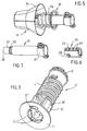
- the chemical sealing system in the embodiment of FIGS. 1 and 2, is intended for the sealing of a threaded rod 1 in a hollow material with an outer wall 2, here a brick.
- the system comprises, in addition to the rod 1, a one-piece return element 3, of generally tubular shape, comprising a return spring 4 of which are secured, on one side, a bushing 5 for receiving the rod 1 and, from the on the other side, by means of axial ribs 6, a support flange 7.
- the system also comprises a sheath-envelope 8 comprising an end sleeve 9 to which are attached and hinged in an elastic manner blades, or plates, flexible 10 of here trapezoidal shape and which can therefore be folded back or, in the rest state , deployed as an umbrella, with a flare in the direction of their free edges 11.
- the sheath 8 is mounted, by its sleeve 9, on the sleeve 5.
- the flange 7 is provided with a lumen 17 for the passage of a resin mortar injection nozzle.
- the sleeve 9 of the sheath-envelope 8 can be force-fitted onto the socket 5. It could also be a bayonet mount, as with the socket 5 'of the return element 3' of FIG. 3 The sheath sleeve 9 '' could also be clipped onto the socket 5 '' of the system in Figure 4.
- the sleeve 5 is internally provided with a tapping which cooperates with the thread of the rod 1, as shown in FIG. 4.
- the internal wall of the sleeve could carry, out of the mold, only axial ribs in which the threaded rod itself would perform the tapping.
- the return element is in one piece, that is to say that it was produced by a single injection into a mold. It is then easy to adapt the internal thread of the end sleeve to different diameters of threaded rod by suitable drawers, without changing the other parts of the mold. In this case, provision is made at the flange 7 'for centering fins 12' (FIG. 3) with a passage diameter adaptable to that of the threaded rod.
- the sheath-envelope 8 is a split sheath with almost contiguous plates.
- the rod is provided with means anti-rotation or anchoring. It may be a flat 13, as on the rod of the system of FIG. 4. More generally, the rod will be shaped to present, at least over part of its length, a non-circular section, for example triangular, rectangular, cruciform ....
- the passage section between the ribs 6 is greater than the diameter of the rod 1, the rod 1 extending freely inside the return element 3, except in the socket 5 with which it cooperates.
- the ribs 6 'of the element of Figure 3 are attached to a sleeve portion 18' but whose inner diameter remains larger than the diameter of the rod 1 on which it can freely slide.
- the spring allows the system to be used for walls of different thicknesses.
- the sheath 8 deploys elastically in the rest state and, under the action of spring 4, the plates 10 of the sheath, with the rod 1, are pushed back into the sealing position, with their edges 11 abutting against the internal face 16 of the wall 2.
- ribs 6 constitute a means of centering the sealing system in the orifice 14 of the wall 2.
- the length of the portion of the rod 1 then protruding outside the wall is then adjusted by screwing or unscrewing the rod into the 5 "socket. Then, through the lumen 17 of the collar 7, the l injection nozzle and a resin mortar is injected which flows between the ribs 6 and into the space delimited by the plates 10 of the sheath-envelope 8 and the resin mortar is allowed to harden before fixing the part to The rod is sealed by hanging resin mortar in the threads of the rod thread.
- the sealing system as just described resembles a sheath open towards the inner face of the wall and pinched between its bottom and this wall. Thanks to this, the sheath perfectly contains the resin mortar before it hardens, and whatever its viscosity. By the injection pressure and the pressure exerted by the sheath, the resin mortar adheres well to the interior face of the wall.
- the sealing system always includes a fixing sleeve 25, particular as will appear below, on which is mounted a sheath-envelope 48, very similar to that of the embodiment of the Figures 1-4.
- the particularity of the sleeve 25 is that it was formed from a cut and rolled sheet metal side. It comprises, in an axial plane, two lateral anchoring ribs 26, obtained by pinching, and comprising, in a series of radial planes, cutouts 27 constituting thread portions.
- the sleeve 25 also has a lateral cutout 28 for the flow of the resin mortar. Finally, the sleeve 25 is internally tapped.
- the sheath-envelope 48 is bayonet-mounted on the bush 25 by its thread portions.
- the system comprises, as return means, a spring 29, "screwed", by a series of turns 34 from one end, onto the bush 25 and comprising, at its other end, a series enlarged turns 30 intended to act as a support flange against the external face 15 of the wall 2.
- the sleeve 25 With the sleeve 25 is associated a tubular end piece 31 with an end portion 32 of narrowed outer diameter and partly threaded 33 so that it can be first introduced into the sleeve and then screwed into it in a quasi-hermetic manner.
- the end piece 31 At its other end, the end piece 31 here carries a ring with maneuvering handles 35.
- the internal section of the narrowed portion 32 of the end piece 31 is not circular, it is here hexagonal, in order to be able to ensure, after injection of the resin mortar, clearing the hardened mortar column from the socket 25.
- the system After having drilled a sealing hole 36 and dismantled the sheath-envelope, the system is introduced into the hole 36 until the end turns 30 of the spring 29 bear against the surface 37 of the material, the spring 29 , by its turns adjacent to the end turns 30, keeping the system suitably centered in the hole.
- a resin mortar is injected which flows inside the end piece and exits through the cutout 28 from the socket 25 to spread in the hole 36, between the wall of the hole and the socket and the end-piece.
- the end piece 31 is unscrewed, which has the effect of shearing the column of mortar extending inside the end piece flush with the end 38 of the narrowed portion 32 of the end piece .
- the internal thread of the sleeve having been protected over a length equal to that of the narrowed portion 32 of the end piece, it is possible to engage in the circular hole preserved by the end piece , a fixing screw and screw it into the socket.
Landscapes
- Engineering & Computer Science (AREA)
- General Engineering & Computer Science (AREA)
- Mechanical Engineering (AREA)
- Dowels (AREA)
- Working Measures On Existing Buildindgs (AREA)
- Furnace Housings, Linings, Walls, And Ceilings (AREA)
- Catching Or Destruction (AREA)
- Refuge Islands, Traffic Blockers, Or Guard Fence (AREA)
- Physical Or Chemical Processes And Apparatus (AREA)
Claims (4)
- System zur chemischen Versiegelung eines Befestigungselements in einem hohlen Material mit Außenwand (2), mit einem Hülsengehäuse (8; 28) mit variabler Verformung, das an einer Buchse (5; 25) mit Innengewinde zur Aufnahme des Befestigungselements (1) angebracht ist, wobei die Hülse derart angeordnet ist, daß sie im eingeklappten Zustand eine in die Außenwand (2) des Materials gebohrte Öffnung (14) durchdringen und über die Öffnung hinaus in einer Versiegelungsposition gelangen und im entfalteten Zustand einen Mörtel aus aushärtendem Harz umschließen kann, dadurch gekennzeichnet, daß das Hülsengehäuse (8; 28) derart angeordnet ist, daß es sich in der Ruhestellung elastisch entfaltet und in der Versiegelungsstellung zu der Außenwand (2) aufgeweitet und in Anlage gegen die Innenseite (16) ist, und zwar unter der Wirkung vonRückstellmitteln (4; 29), die mit der Buchse (5; 25) fest verbunden sind, sowie vonMitteln (7; 30) zur Anlage gegen die Außenseite (15) der Außenwand (2), die mit den Rückstellmitteln (4; 29) fest verbunden sind.
- System nach Anspruch 1, bei dem ein Befestigungsgewindestift (1) zum Versiegeln in die Buchse (5) geschraubt ist.
- System nach Anspruch 2, bei dem die Mittel zur Anlage gegen die Außenseite (15) der Außenwand (2) einen Flansch (7) aufweisen, der mit einem Schlitzloch (17) zum Durchgang eines Einspritzansatzes für Harzmörtel versehen ist.
- System nach Anspruch 3, bei dem der Anlageflansch (7') Flügel (12') zum Zentrieren des Gewindestifts mit einem Durchgangsdurchmesser aufweist, der an denjenigen des Gewindestifts (1) angepaßt werden kann.
Applications Claiming Priority (2)
| Application Number | Priority Date | Filing Date | Title |
|---|---|---|---|
| FR9206499 | 1992-05-27 | ||
| FR9206499A FR2691764B1 (fr) | 1992-05-27 | 1992-05-27 | Systeme de scellement chimique d'un element de fixation dans un materiau creux. |
Publications (2)
| Publication Number | Publication Date |
|---|---|
| EP0572296A1 EP0572296A1 (de) | 1993-12-01 |
| EP0572296B1 true EP0572296B1 (de) | 1997-08-20 |
Family
ID=9430238
Family Applications (1)
| Application Number | Title | Priority Date | Filing Date |
|---|---|---|---|
| EP19930401198 Expired - Lifetime EP0572296B1 (de) | 1992-05-27 | 1993-05-11 | System zum chemischen Einmauern von einem Befestigungselement in einem hohlen Material |
Country Status (5)
| Country | Link |
|---|---|
| EP (1) | EP0572296B1 (de) |
| CA (1) | CA2097034C (de) |
| DE (1) | DE69313182T2 (de) |
| ES (1) | ES2107637T3 (de) |
| FR (1) | FR2691764B1 (de) |
Families Citing this family (1)
| Publication number | Priority date | Publication date | Assignee | Title |
|---|---|---|---|---|
| DE102009013847A1 (de) | 2009-03-18 | 2010-09-23 | Fischerwerke Gmbh & Co. Kg | Ankerhülse |
Family Cites Families (6)
| Publication number | Priority date | Publication date | Assignee | Title |
|---|---|---|---|---|
| GB1340117A (en) * | 1972-06-30 | 1973-12-12 | Houston T R | Anchorage pins |
| SE365588B (de) * | 1972-09-27 | 1974-03-25 | Thorsmansdoedsbo O | |
| DE2453957B2 (de) * | 1974-11-14 | 1976-11-18 | Fischer, Artur, Dr., 7244 Waldachtal | Verankerung eines befestigungselementes |
| DE2723729C2 (de) * | 1977-05-26 | 1979-04-05 | Fischer, Artur, Dr.H.C., 7244 Waldachtal | Verankerung eines Befestigungselementes in einem Bohrloch eines Hohlräume aufweisenden Mauerwerks |
| DE3325800A1 (de) * | 1983-07-16 | 1985-01-31 | Heinrich 6102 Pfungstadt Liebig | Klebeanker |
| DE3712463A1 (de) * | 1987-04-13 | 1988-10-27 | Hilti Ag | Befestigung auf hohlraeume aufweisendem untergrund |
-
1992
- 1992-05-27 FR FR9206499A patent/FR2691764B1/fr not_active Expired - Lifetime
-
1993
- 1993-05-11 ES ES93401198T patent/ES2107637T3/es not_active Expired - Lifetime
- 1993-05-11 DE DE1993613182 patent/DE69313182T2/de not_active Expired - Fee Related
- 1993-05-11 EP EP19930401198 patent/EP0572296B1/de not_active Expired - Lifetime
- 1993-05-26 CA CA 2097034 patent/CA2097034C/en not_active Expired - Fee Related
Also Published As
| Publication number | Publication date |
|---|---|
| CA2097034C (en) | 1996-04-23 |
| FR2691764A1 (fr) | 1993-12-03 |
| FR2691764B1 (fr) | 1995-08-25 |
| DE69313182D1 (de) | 1997-09-25 |
| ES2107637T3 (es) | 1997-12-01 |
| DE69313182T2 (de) | 1998-03-05 |
| EP0572296A1 (de) | 1993-12-01 |
| CA2097034A1 (en) | 1993-11-28 |
Similar Documents
| Publication | Publication Date | Title |
|---|---|---|
| FR2513331A1 (fr) | Boulon d'ancrage a expansion | |
| FR2491562A1 (fr) | Rivet en deux parties | |
| EP0029475A1 (de) | Vorrichtung zum Befestigen oder Sichern eines Gegenstandes auf einem Schaft | |
| FR2489902A1 (fr) | Element de liaison | |
| EP0228930A1 (de) | Verbindungsvorrichtung für Röhren oder Stäbe | |
| EP1813826B1 (de) | Vorrichtung für eine lösbare Verbindung, die eine Verriegelungsklammer umfasst | |
| WO2005035336A1 (fr) | Obturateur pour partie creuse de vehicule automobile | |
| EP0402223B1 (de) | Verankerunsdübel in einem hinterschnittenen Loch | |
| FR2756334A1 (fr) | Dispositif de fixation, support d'accrochage le comportant et son utilisation pour un pare-soleil de vehicule | |
| EP0268510B1 (de) | Vorrichtung zur Blindbefestigung von mindestens zwei Teilen, zum Beispiel Bleche | |
| EP0572296A1 (de) | System zum chemischen Einmauern von einem Befestigungselement in einem hohlen Material | |
| EP1231422B1 (de) | Verfahren zur Herstellung einer unverlierbaren Schraube, Fixierungstellringe für Rohrleitungen und Gebrauch von dem Prozess, die Stellringe herzustellen | |
| FR2628461A1 (fr) | Barre pour construction multidimensionnelle en treillis | |
| EP2446155B1 (de) | Plastikmutter-befestigungvorrichtung | |
| FR2925627A1 (fr) | Dispositif de fixation et procede de serrage d'une piece. | |
| FR2733285A1 (fr) | Dispositif de fixation mecanique rigide destine a une rotule, ensemble le comprenant et procedes de montage et demontage | |
| FR2611005A1 (fr) | Cheville a expansion en matiere plastique | |
| FR2516610A1 (fr) | Cheville expansible | |
| WO1998053214A1 (fr) | Dispositif de fixation d'un element a un support mince | |
| FR2607201A1 (fr) | Dispositif de fixation sur fut filete ou annele | |
| FR2699617A1 (fr) | Insert à douille et élément fileté. | |
| WO2013160459A1 (fr) | Organe de fixation d'un accessoire sur un support ainsi que du support sur une structure | |
| EP0135427B1 (de) | Zentrierungs- und Führungsring für Befestigungselement | |
| FR2726063A1 (fr) | Dispositif de coupure de debit de fluide en cas de sur-debit | |
| FR2668240A1 (fr) | Dispositif de raccordement de deux tuyaux de part et d'autre d'un element de cloison. |
Legal Events
| Date | Code | Title | Description |
|---|---|---|---|
| PUAI | Public reference made under article 153(3) epc to a published international application that has entered the european phase |
Free format text: ORIGINAL CODE: 0009012 |
|
| AK | Designated contracting states |
Kind code of ref document: A1 Designated state(s): BE DE ES FR GB IT SE |
|
| 17P | Request for examination filed |
Effective date: 19940415 |
|
| 17Q | First examination report despatched |
Effective date: 19950511 |
|
| GRAG | Despatch of communication of intention to grant |
Free format text: ORIGINAL CODE: EPIDOS AGRA |
|
| GRAH | Despatch of communication of intention to grant a patent |
Free format text: ORIGINAL CODE: EPIDOS IGRA |
|
| GRAH | Despatch of communication of intention to grant a patent |
Free format text: ORIGINAL CODE: EPIDOS IGRA |
|
| GRAA | (expected) grant |
Free format text: ORIGINAL CODE: 0009210 |
|
| AK | Designated contracting states |
Kind code of ref document: B1 Designated state(s): BE DE ES FR GB IT SE |
|
| REF | Corresponds to: |
Ref document number: 69313182 Country of ref document: DE Date of ref document: 19970925 |
|
| GBT | Gb: translation of ep patent filed (gb section 77(6)(a)/1977) |
Effective date: 19971021 |
|
| ITF | It: translation for a ep patent filed | ||
| REG | Reference to a national code |
Ref country code: ES Ref legal event code: FG2A Ref document number: 2107637 Country of ref document: ES Kind code of ref document: T3 |
|
| PLBE | No opposition filed within time limit |
Free format text: ORIGINAL CODE: 0009261 |
|
| STAA | Information on the status of an ep patent application or granted ep patent |
Free format text: STATUS: NO OPPOSITION FILED WITHIN TIME LIMIT |
|
| 26N | No opposition filed | ||
| REG | Reference to a national code |
Ref country code: GB Ref legal event code: IF02 |
|
| PGFP | Annual fee paid to national office [announced via postgrant information from national office to epo] |
Ref country code: SE Payment date: 20080529 Year of fee payment: 16 |
|
| PGFP | Annual fee paid to national office [announced via postgrant information from national office to epo] |
Ref country code: ES Payment date: 20090526 Year of fee payment: 17 |
|
| PGFP | Annual fee paid to national office [announced via postgrant information from national office to epo] |
Ref country code: IT Payment date: 20090528 Year of fee payment: 17 Ref country code: DE Payment date: 20090528 Year of fee payment: 17 |
|
| PGFP | Annual fee paid to national office [announced via postgrant information from national office to epo] |
Ref country code: BE Payment date: 20090624 Year of fee payment: 17 |
|
| PGFP | Annual fee paid to national office [announced via postgrant information from national office to epo] |
Ref country code: GB Payment date: 20090528 Year of fee payment: 17 |
|
| BERE | Be: lapsed |
Owner name: SOC. DE PROSPECTION ET D'INVENTIONS TECHNIQUES *SP Effective date: 20100531 |
|
| GBPC | Gb: european patent ceased through non-payment of renewal fee |
Effective date: 20100511 |
|
| PG25 | Lapsed in a contracting state [announced via postgrant information from national office to epo] |
Ref country code: IT Free format text: LAPSE BECAUSE OF NON-PAYMENT OF DUE FEES Effective date: 20100511 Ref country code: BE Free format text: LAPSE BECAUSE OF NON-PAYMENT OF DUE FEES Effective date: 20100531 |
|
| PG25 | Lapsed in a contracting state [announced via postgrant information from national office to epo] |
Ref country code: DE Free format text: LAPSE BECAUSE OF NON-PAYMENT OF DUE FEES Effective date: 20101201 |
|
| PG25 | Lapsed in a contracting state [announced via postgrant information from national office to epo] |
Ref country code: SE Free format text: LAPSE BECAUSE OF NON-PAYMENT OF DUE FEES Effective date: 20090512 |
|
| REG | Reference to a national code |
Ref country code: ES Ref legal event code: FD2A Effective date: 20110715 |
|
| PG25 | Lapsed in a contracting state [announced via postgrant information from national office to epo] |
Ref country code: ES Free format text: LAPSE BECAUSE OF NON-PAYMENT OF DUE FEES Effective date: 20110705 Ref country code: GB Free format text: LAPSE BECAUSE OF NON-PAYMENT OF DUE FEES Effective date: 20100511 |
|
| PGFP | Annual fee paid to national office [announced via postgrant information from national office to epo] |
Ref country code: FR Payment date: 20110607 Year of fee payment: 19 |
|
| PG25 | Lapsed in a contracting state [announced via postgrant information from national office to epo] |
Ref country code: ES Free format text: LAPSE BECAUSE OF NON-PAYMENT OF DUE FEES Effective date: 20100512 |
|
| REG | Reference to a national code |
Ref country code: FR Ref legal event code: ST Effective date: 20130131 |
|
| PG25 | Lapsed in a contracting state [announced via postgrant information from national office to epo] |
Ref country code: FR Free format text: LAPSE BECAUSE OF NON-PAYMENT OF DUE FEES Effective date: 20120531 |