EP0572467B1 - Wärmetauscher - Google Patents
Wärmetauscher Download PDFInfo
- Publication number
- EP0572467B1 EP0572467B1 EP92904877A EP92904877A EP0572467B1 EP 0572467 B1 EP0572467 B1 EP 0572467B1 EP 92904877 A EP92904877 A EP 92904877A EP 92904877 A EP92904877 A EP 92904877A EP 0572467 B1 EP0572467 B1 EP 0572467B1
- Authority
- EP
- European Patent Office
- Prior art keywords
- heat exchanger
- plate elements
- inlet
- matrix
- process stream
- Prior art date
- Legal status (The legal status is an assumption and is not a legal conclusion. Google has not performed a legal analysis and makes no representation as to the accuracy of the status listed.)
- Expired - Lifetime
Links
Images


Classifications
-
- F—MECHANICAL ENGINEERING; LIGHTING; HEATING; WEAPONS; BLASTING
- F28—HEAT EXCHANGE IN GENERAL
- F28F—DETAILS OF HEAT-EXCHANGE AND HEAT-TRANSFER APPARATUS, OF GENERAL APPLICATION
- F28F9/00—Casings; Header boxes; Auxiliary supports for elements; Auxiliary members within casings
- F28F9/007—Auxiliary supports for elements
- F28F9/0075—Supports for plates or plate assemblies
-
- F—MECHANICAL ENGINEERING; LIGHTING; HEATING; WEAPONS; BLASTING
- F28—HEAT EXCHANGE IN GENERAL
- F28D—HEAT-EXCHANGE APPARATUS, NOT PROVIDED FOR IN ANOTHER SUBCLASS, IN WHICH THE HEAT-EXCHANGE MEDIA DO NOT COME INTO DIRECT CONTACT
- F28D9/00—Heat-exchange apparatus having stationary plate-like or laminated conduit assemblies for both heat-exchange media, the media being in contact with different sides of a conduit wall
- F28D9/0006—Heat-exchange apparatus having stationary plate-like or laminated conduit assemblies for both heat-exchange media, the media being in contact with different sides of a conduit wall the plate-like or laminated conduits being enclosed within a pressure vessel
-
- F—MECHANICAL ENGINEERING; LIGHTING; HEATING; WEAPONS; BLASTING
- F28—HEAT EXCHANGE IN GENERAL
- F28D—HEAT-EXCHANGE APPARATUS, NOT PROVIDED FOR IN ANOTHER SUBCLASS, IN WHICH THE HEAT-EXCHANGE MEDIA DO NOT COME INTO DIRECT CONTACT
- F28D9/00—Heat-exchange apparatus having stationary plate-like or laminated conduit assemblies for both heat-exchange media, the media being in contact with different sides of a conduit wall
- F28D9/0031—Heat-exchange apparatus having stationary plate-like or laminated conduit assemblies for both heat-exchange media, the media being in contact with different sides of a conduit wall the conduits for one heat-exchange medium being formed by paired plates touching each other
-
- F—MECHANICAL ENGINEERING; LIGHTING; HEATING; WEAPONS; BLASTING
- F28—HEAT EXCHANGE IN GENERAL
- F28F—DETAILS OF HEAT-EXCHANGE AND HEAT-TRANSFER APPARATUS, OF GENERAL APPLICATION
- F28F2230/00—Sealing means
-
- F—MECHANICAL ENGINEERING; LIGHTING; HEATING; WEAPONS; BLASTING
- F28—HEAT EXCHANGE IN GENERAL
- F28F—DETAILS OF HEAT-EXCHANGE AND HEAT-TRANSFER APPARATUS, OF GENERAL APPLICATION
- F28F2250/00—Arrangements for modifying the flow of the heat exchange media, e.g. flow guiding means; Particular flow patterns
- F28F2250/10—Particular pattern of flow of the heat exchange media
- F28F2250/108—Particular pattern of flow of the heat exchange media with combined cross flow and parallel flow
-
- Y—GENERAL TAGGING OF NEW TECHNOLOGICAL DEVELOPMENTS; GENERAL TAGGING OF CROSS-SECTIONAL TECHNOLOGIES SPANNING OVER SEVERAL SECTIONS OF THE IPC; TECHNICAL SUBJECTS COVERED BY FORMER USPC CROSS-REFERENCE ART COLLECTIONS [XRACs] AND DIGESTS
- Y10—TECHNICAL SUBJECTS COVERED BY FORMER USPC
- Y10S—TECHNICAL SUBJECTS COVERED BY FORMER USPC CROSS-REFERENCE ART COLLECTIONS [XRACs] AND DIGESTS
- Y10S165/00—Heat exchange
- Y10S165/355—Heat exchange having separate flow passage for two distinct fluids
- Y10S165/356—Plural plates forming a stack providing flow passages therein
- Y10S165/387—Plural plates forming a stack providing flow passages therein including side-edge seal or edge spacer bar
- Y10S165/388—Plural plates forming a stack providing flow passages therein including side-edge seal or edge spacer bar including spacer bar transverse to plate stack
-
- Y—GENERAL TAGGING OF NEW TECHNOLOGICAL DEVELOPMENTS; GENERAL TAGGING OF CROSS-SECTIONAL TECHNOLOGIES SPANNING OVER SEVERAL SECTIONS OF THE IPC; TECHNICAL SUBJECTS COVERED BY FORMER USPC CROSS-REFERENCE ART COLLECTIONS [XRACs] AND DIGESTS
- Y10—TECHNICAL SUBJECTS COVERED BY FORMER USPC
- Y10S—TECHNICAL SUBJECTS COVERED BY FORMER USPC CROSS-REFERENCE ART COLLECTIONS [XRACs] AND DIGESTS
- Y10S165/00—Heat exchange
- Y10S165/355—Heat exchange having separate flow passage for two distinct fluids
- Y10S165/40—Shell enclosed conduit assembly
- Y10S165/427—Manifold for tube-side fluid, i.e. parallel
- Y10S165/432—Manifold for tube-side fluid, i.e. parallel including a tube sheet
- Y10S165/433—Tubes-tubesheet connection
Definitions
- This invention relates to heat exchangers of the kind generally known as plate-fin heat exchangers, though they also have some similarities to the shell-tube type.
- the fluid passages in plate-fin heat exchangers are defined by partitions of a metal which has a satisfactorily high coefficient of heat transfer, so that when a high temperature fluid is passed through some passages and low temperature fluid is passed through further passages which are adjacent thereto, there results a cooling of the originally high temperature fluid, by heat conduction through the thickness of the partitions into the cool fluid.
- Efficiency of heat exchange is boosted by inclusion in the fluid flow passages of so-called "fins”, which may in fact be corrugated members, dimples, grooves, protuberances, baffles or other turbulence promoters, instead of fins as such.
- Plate-fin heat exchangers offer significant advantages over shell-tube heat exchangers in terms of weight, space, thermal efficiency and the ability to handle several process streams - i.e. several streams of heat exchange media - at once.
- most current plate-fin heat exchanger technology is centred on a brazed matrix construction using aluminium components and is therefore limited to low pressure and low temperature operation. Even using other materials, such as stainless steel, operational pressure limits (say, 80-90 bar) apply because of brazing as the method of fabrication.
- EP-A-0 414 435 falling under Article 54(3) EPC discloses alternative ways of manufacturing plate-fin heat exchanger elements which help to avoid the above problems and allow greater flexibility in their design.
- they describe a method of manufacturing heat exchange plate elements in which metal (e.g. titanium or stainless steel) sheets are stacked together and selectively diffusion bonded to each other before being superplastically deformed to a final hollow shape defining internal passages, which can incorporate integrally formed "fins".
- metal e.g. titanium or stainless steel
- Use of superplastic deformation in the manufacturing process enables the generation of high volume fractions of hollowness in a heat exchanger element.
- the result is a high integrity, low weight heat exchanger element.
- use of titanium alloy materials to produce heat exchanger elements by the diffusion bonding and superplastic forming route enables their operation at pressures in excess of 200 bar and at temperatures up to 300°C, whereas stainless steel materials enable even better performance.
- DE3924581 discloses a heat exchanger comprising a matrix of heat exchange plate elements which are welded together so that they are in contact with each other.
- the plate elements do not have a superplastically expanded internal core structure sandwiched between the sheets of the plate elements.
- US3927817 discloses a process for superplastically expanding an internal core structure sandwiched between two sheets.
- One object of the present invention is to facilitate easy manufacture and assembly of heat exchangers incorporating matrices of such superplastically formed/diffusion bonded heat exchanger plate elements.
- a plate-fin type of heat exchanger for facilitating exchange of heat between two process streams, comprising
- the plate elements have edge portions which are thin relative to portions of the plate elements having the expanded internal core structure, adjacent plate elements being held in position in the matrix relative to each other by serrated tiebar means which engage the thin edges of the plate elements.
- At least the inlet manifold means for at least the first process stream is detachable from the metal jacket means, the heat exchanger matrix being removable from the metal jacket means together with the inlet manifold means.
- the superplastically expanded core structure within the plate elements comprises a single superplastically expanded metal sheet.
- an inlet or outlet manifold means for at least the first process stream comprises manifold wall means having slots therethrough, the projecting edge portions of the plate elements being secured in the slots such that process stream flow can occur through the manifold into the interior of the plate elements.
- outer sheets and the internal core structure are made of superplastically formable material.
- Superplasticity is a deformation phenomenon which allows some materials to strain by large amounts without the initiating of tensile instability or necking. This enables the generation of high volume fractions of hollowness in a heat exchanger matrix, while allowing designs of good mechanical and thermal performance, together with low weight and high utilisation of material.
- Diffusion bonding is a metal interface phenomenon in which, provided clean metal surfaces at a suitable temperature are protected from surface contamination by the provision of a suitable joint face environment, and sufficient pressure is applied to the mating surfaces, then solid state diffusion of the metal atoms across the boundary takes place to such an extent that subsequently no interface can be detected. No macroscopic deformation takes place during bonding and therefore shape and size stability is maintained during the operation.
- the joint produced has parent metal properties without the presence of a heat affected zone or other material such as a flux or bond promoter. Its use within a heat exchanger therefore reduces the possibility of chemical interaction with process fluids.
- the heat exchanger plate elements shown in Figures 2 to 5 are manufactured by a superplastic forming/diffusion bonding process which will first be briefly described in a simplified manner with reference to Figure 1. For fuller details of manufacture, reference should be made to our earlier patent applications EP90308923.3 and GB9012618.6.
- three superplastically formable metal sheets 101,102,103 (made of, for example, a suitable titanium alloy), of near net shape and controlled surface finish, are cleaned to a high standard and a bond inhibitor is deposited onto selected areas (shown as white) of the joint faces 105,107 of the two outer sheets 101,103. Bare metal areas are shown hatched, or as lines or dots.
- the deposit specifies the ultimate internal configuration of the finished heat exchanger plate element, and comprises areas defining process stream inlets 109 and outlets 111, inlet and outlet flow distributor regions 113 and 115 respectively, and flow passages 117 within the element. Edge regions E of the sheets 101,103, where it is not desired to produce an internal structure, do not have any bond inhibitor applied.
- the deposition process e.g. silk screen printing, allows considerable flexibility of design to satisfy both mechanical and thermal requirements.
- the sheets 101,102,103 are then stacked and diffusion bonded together in the manner detailed in our earlier patent applications, resulting in a bonded stack 121, which is placed in a closed die 123 as shown schematically in cross-section in Figure 1B.
- the bonded stack 121 and the die 123 are heated to superplastic forming temperature and the stack's interior structure, as defined by the pattern of bond inhibitor 125, is injected with inert gas at high pressure to inflate the stack so that the outer sheets 101,103 move apart against the die forms.
- the outer sheet 101 As the outer sheet 101 expands superplastically into the die cavity, it pulls the middle or core sheet 102 with it where diffusion bonding has occurred. Superplastic deformation of the core sheet 102 therefore also occurs to form a hollow interior which is partitioned by the stretched portions 127 of the core sheet 102, thereby creating passages 117 through which a process stream can flow. The edge regions E of the stack 121 remain fully bonded, and therefore flat and unexpanded.
- each article so produced is trimmed around its edges, along the dashed line indicated in Figure 1A. This creates openings into those parts of the expanded internal structure which define the inlet 109 and outlet 111, these being revealed as expanded rectangular slots in otherwise thin edges of the articles.
- the line of the trimming is such as to leave projecting edge portions or tangs T on the outer sheets 101,103 at opposed edges of the formed article. These tangs T define the openings to the inlet slot 109 and the outlet slot 111.
- the inlet slot 109 and the outlet slot 111 are, for the purposes of the present embodiment, completely opened up internally for flow of a single stream of the process fluid by an internal milling or routing operation to cut away obscuring portions of the core sheet 102.
- the superplastic forming/diffusion bonding process outlined above results in the production of very accurately formed external surfaces for sheets 101,103, which enable good conformance of each heat exchanger element to its neighbours in a matrix of such elements.
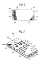
- the heat exchanger plate element 200 illustrated has a core structure 201 comprising the single core sheet 102.
- the inlet 109 is merely a gap between sheets 101 and 103 where the core sheet 102 has been cut away by the above-mentioned routing or milling operation to the extent shown by the dotted lines. This allows the process fluid to flow on both sides of the core sheet 102 and hence, after traversing the inlet distributor region 113, into all the passages 117 formed alternately between the core sheet 102 and the outer sheets 101,103.
- the inlet 109 opens directly into the inlet flow distributor region 113, which is a region where the bond inhibitor was not applied to numerous small circular areas or dots 203 on both the joint faces 105,107 of the outer sheets, see Figure lA. These dots 203 are arranged in rows as shown, with each dot on a given joint face 105 being positioned midway between each group of four dots on the other joint face 107. Of course, other dot patterns may be used at the discretion of the designer. At these dots 203 the core sheet 102 is diffusion bonded to the outer sheets 101,103 and during the superplastic forming operation the core sheet 102 is expanded to the double cusped configuration shown in Figure 3.
- the major part of the core structure 201 consists simply of straight line corrugations formed in the core sheet 102. These corrugations are of such a form that, in conjunction with the outer sheets 101,103, longitudinally straight flow passages 117 with a trapezoid shaped cross-section are defined. As shown in Figure 3, the transition between the so-called “dot core” distributor regions 113 and the "line core” passage region is easily arranged.
- the core structure 201 consists of a single sheet 102, though it could consist of more than one sheet if a more complex core structure 201 is required.
- the present embodiment is concerned with a simple heat exchanger plate element in which one process stream S1 flows through it on both sides of the core sheet 102 and therefore through all the passages 117 in the core structure.
- Another process stream S2 with which process stream S1 exchanges heat, flows over the outside surfaces of the heat exchanger plate element 200. Consequently, the primary heat exchange surfaces are the surfaces of the outer sheets 101,103, whereas the secondary heat exchange surfaces, designated “fins", are the surfaces of the core sheet 102 forming the partitions between the flow passages 117.
- the core sheet could be formed into the cusped configuration of the distributor regions 113,115 throughout its whole extent.
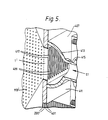
- FIGS 4 and 5 show how a large number of heat exchanger plate elements 200' can be assembled into a matrix M to form a complete heat exchanger 400.
- Heat exchanger elements 200' are similar to elements 200, except that their distributor regions 113' are arranged symmetrically about their longitudinal centrelines.
- the high-integrity superplastically formed and diffusion bonded plate elements 200' may be used to carry a high pressure methane stream S1 in internal passages 117', while seawater for cooling purposes may comprise the other stream S2, which flows through passages 401 between adjacent elements 200'.
- the individual elements 200' in the matrix M are held separated from each other and in their correct positions by toothed tie-bars or racks 403 which engage the thin, flat, unexpanded parts of the elements on their opposed edges.
- the completed matrix is then inserted into a fabricated steel jacket 405.
- the gas header or inlet manifold tank 407 is formed by inserting the edge tangs T' (similar to Figure 2) of the outer sheets of the elements 200' into slots 409 in a flat plate 411 to which a cast half-cylindrical component 413, with integral inlet stub pipe 415, is welded.
- the header tank 407 is completed by semicircular end plates (not shown). The ends of the tangs T' are welded directly to the edges of the slots 409 to form weld beads 417 which outline the slots.
- the inlet pipe 415 which feeds the gas header tank 407 passes through a gland box assembly 419 which is bolted to an end plate 421 of the steel jacket 405.
- This is similar to the well-known "floating head” arrangement used in shell and tube heat exchangers, and in conjunction with the way in which the end plate 421 is bolted to the rest of the steel jacket 405, enables easy removal of the entire heat exchanger matrix from the jacket 405.
- a sea water header or inlet manifold tank 423 is formed simply by welding the half-cylindrical component 425, with integral inlet stub pipe 427, over a rectangular cut-out 429 in the top surface of the jacket. Water is thus fed directly to the passages 401 between the elements 200' of the heat exchanger matrix M.
- gas and water outlet manifolds 431 and 433 are not shown in detail, but are similar to the constructions of the gas and water inlet headers just described.
- suitable flow distributing features such as dimples, grooves, protrusions or fins may be provided if necessary on the outer surfaces of the elements 200'. These may be formed during the superplastic forming phase of the element manufacture by corresponding shapes on the superplastic forming dies. Alternatively, chemical etching may be used to produce such features, or baffles may be welded to the surfaces.
- This invention relates to heat exchangers of the kind generally known as plate-fin heat exchangers, though they also have some similarities to the shell-tube type.
- the fluid passages in plate-fin heat exchangers are defined by partitions of a metal which has a satisfactorily high coefficient of heat transfer, so that when a high temperature fluid is passed through some passages and low temperature fluid is passed through further passages which are adjacent thereto, there results a cooling of the originally high temperature fluid, by heat conduction through the thickness of the partitions into the cool fluid.
- Efficiency of heat exchange is boosted by inclusion in the fluid flow passages of so-called "fins”, which may in fact be corrugated members, dimples, grooves, protuberances, baffles or other turbulence promoters, instead of fins as such.
- Plate-fin heat exchangers offer significant advantages over shell-tube heat exchangers in terms of weight, space, thermal efficiency and the ability to handle several process streams - i.e. several streams of heat exchange media - at once.
- most current plate-fin heat exchanger technology is centred on a brazed matrix construction using aluminium components and is therefore limited to low pressure and low temperature operation. Even using other materials, such as stainless steel, operational pressure limits (say, 80-90 bar) apply because of brazing as the method of fabrication.
- DE3924581 discloses an example of such a heat exchanger comprising a matrix of heat exchange plate elements which are welded together so that they are in contact with each other.
- US3927817 discloses a process for superplastically expanding an internal core structure sandwiched between two sheets.
- the present invention seeks to provide a heat exchanger with improved structural integrity that can be used over an improved range of operation.
- the invention also seeks to provide a heat exchanger that is easy to manufacture and allows a large degree of design flexibility.
- a plate-fin type of heat exchanger for facilitating exchange of heat between two process streams, comprising
- the plate elements have edge portions which are thin relative to portions of the plate elements having the expanded internal core structure, adjacent plate elements being held in position in the matrix relative to each other by serrated tiebar means which engage the thin edges of the plate elements.
- At least the inlet manifold means for at least the first process stream is detachable from the metal jacket means, the heat exchanger matrix being removable from the metal jacket means together with the inlet manifold means.
- the superplastically expanded core structure within the plate elements comprises a single superplastically expanded metal sheet.
- an inlet or outlet manifold means for at least the first process stream comprises;
- the inlet and outlet passages for flow of the first process stream through the plate elements comprise a gap between the outer sheets wher a portion of the core structure has been cut away.
- outer sheets and the internal core structure are made of superplastically formable material.
- Superplasticity is a deformation phenomenon which allows some materials to strain by large amounts without the initiating of tensile instability or necking. This enables the generation of high volume fractions of hollowness in a heat exchanger matrix, while allowing designs of good mechanical and thermal performance, together with low weight and high utilisation of material.
- Diffusion bonding is a metal interface phenomenon in which, provided clean metal surfaces at a suitable temperature are protected from surface contamination by the provision of a suitable joint face environment, and sufficient pressure is applied to the mating surfaces, then solid state diffusion of the metal atoms across the boundary takes place to such an extent that subsequently no interface can be detected. No macroscopic deformation takes place during bonding and therefore shape and size stability is maintained during the operation.
- the joint produced has parent metal properties without the presence of a heat affected zone or other material such as a flux or bond promoter. Its use within a heat exchanger therefore reduces the possibility of chemical interaction with process fluids.
- the heat exchanger plate elements shown in Figures 2 to 5 are manufactured by a superplastic forming/diffusion bonding process which will first be briefly described in a simplified manner with reference to Figure 1. For fuller details of manufacture, reference should be made to our earlier patent applications EP90308923.3 and GB9012618.6.
- three superplastically formable metal sheets 101,102,103 (made of, for example, a suitable titanium alloy), of near net shape and controlled surface finish, are cleaned to a high standard and a bond inhibitor is deposited onto selected areas (shown as white) of the joint faces 105,107 of the two outer sheets 101,103. Bare metal areas are shown hatched, or as lines or dots.
- the deposit specifies the ultimate internal configuration of the finished heat exchanger plate element, and comprises areas defining process stream inlets 109 and outlets 111, inlet and outlet flow distributor regions 113 and 115 respectively, and flow passages 117 within the element. Edge regions E of the sheets 101,103, where it is not desired to produce an internal structure, do not have any bond inhibitor applied.
- the deposition process e.g. silk screen printing, allows considerable flexibility of design to satisfy both mechanical and thermal requirements.
- the sheets 101,102,103 are then stacked and diffusion bonded together in the manner detailed in our earlier patent applications, resulting in a bonded stack 121, which is placed in a closed die 123 as shown schematically in cross-section in Figure 1B.
- the bonded stack 121 and the die 123 are heated to superplastic forming temperature and the stack's interior structure, as defined by the pattern of bond inhibitor 125, is injected with inert gas at high pressure to inflate the stack so that the outer sheets 101,103 move apart against the die forms.
- the outer sheet 101 As the outer sheet 101 expands superplastically into the die cavity, it pulls the middle or core sheet 102 with it where diffusion bonding has occurred. Superplastic deformation of the core sheet 102 therefore also occurs to form a hollow interior which is partitioned by the stretched portions 127 of the core sheet 102, thereby creating passages 117 through which a process stream can flow. The edge regions E of the stack 121 remain fully bonded, and therefore flat and unexpanded.
- each article so produced is trimmed around its edges, along the dashed line indicated in Figure 1A. This creates openings into those parts of the expanded internal structure which define the inlet 109 and outlet 111, these being revealed as expanded rectangular slots in otherwise thin edges of the articles.
- the line of the trimming is such as to leave projecting edge portions or tangs T on the outer sheets 101,103 at opposed edges of the formed article. These tangs T define the openings to the inlet slot 109 and the outlet slot 111.
- the inlet slot 109 and the outlet slot 111 are, for the purposes of the present embodiment, completely opened up internally for flow of a single stream of the process fluid by an internal milling or routing operation to cut away obscuring portions of the core sheet 102.
- the superplastic forming/diffusion bonding process outlined above results in the production of very accurately formed external surfaces for sheets 101,103, which enable good conformance of each heat exchanger element to its neighbours in a matrix of such elements.
- the heat exchanger plate element 200 illustrated has a core structure 201 comprising the single core sheet 102.
- the inlet 109 is merely a gap between sheets 101 and 103 where the core sheet 102 has been cut away by the above-mentioned routing or milling operation to the extent shown by the dotted lines. This allows the process fluid to flow on both sides of the core sheet 102 and hence, after traversing the inlet distributor region 113, into all the passages 117 formed alternately between the core sheet 102 and the outer sheets 101,103.
- the inlet 109 opens directly into the inlet flow distributor region 113, which is a region where the bond inhibitor was not applied to numerous small circular areas or dots 203 on both the joint faces 105,107 of the outer sheets, see Figure 1A. These dots 203 are arranged in rows as shown, with each dot on a given joint face 105 being positioned midway between each group of four dots on the other joint face 107. Of course, other dot patterns may be used at the discretion of the designer. At these dots 203 the core sheet 102 is diffusion bonded to the outer sheets 101,103 and during the superplastic forming operation the core sheet 102 is expanded to the double cusped configuration shown in Figure 3.
- the major part of the core structure 201 consists simply of straight line corrugations formed in the core sheet 102. These corrugations are of such a form that, in conjunction with the outer sheets 101,103, longitudinally straight flow passages 117 with a trapezoid shaped cross-section are defined. As shown in Figure 3, the transition between the so-called “dot core” distributor regions 113 and the "line core” passage region is easily arranged.
- the core structure 201 consists of a single sheet 102, though it could consist of more than one sheet if a more complex core structure 201 is required.
- the present embodiment is concerned with a simple heat exchanger plate element in which one process stream S1 flows through it on both sides of the core sheet 102 and therefore through all the passages 117 in the core structure.
- Another process stream S2 with which process stream S1 exchanges heat, flows over the outside surfaces of the heat exchanger plate element 200. Consequently, the primary heat exchange surfaces are the surfaces of the outer sheets 101,103, whereas the secondary heat exchange surfaces, designated “fins", are the surfaces of the core sheet 102 forming the partitions between the flow passages 117.
- the core sheet could be formed into the cusped configuration of the distributor regions 113,115 throughout its whole extent.
- FIGS 4 and 5 show how a large number of heat exchanger plate elements 200' can be assembled into a matrix M to form a complete heat exchanger 400.
- Heat exchanger elements 200' are similar to elements 200, except that their distributor regions 113' are arranged symmetrically about their longitudinal centrelines.
- the high-integrity superplastically formed and diffusion bonded plate elements 200' may be used to carry a high pressure methane stream S1 in internal passages 117', while seawater for cooling purposes may comprise the other stream 52, which flows through passages 401 between adjacent elements 200'.
- the individual elements 200' in the matrix M are held separated from each other and in their correct positions by toothed tie-bars or racks 403 which engage the thin, flat, unexpanded parts of the elements on their opposed edges.
- the completed matrix is then inserted into a fabricated steel jacket 405.
- the gas header or inlet manifold tank 407 is formed by inserting the edge tangs T' (similar to Figure 2) of the outer sheets of the elements 200' into slots 409 in a flat plate 411 to which a cast half-cylindrical component 413, with integral inlet stub pipe 415, is welded.
- the header tank 407 is completed by semicircular end plates (not shown). The ends of the tangs T' are welded directly to the edges of the slots 409 to form weld beads 417 which outline the slots.
- the inlet pipe 415 which feeds the gas header tank 407 passes through a gland box assembly 419 which is bolted to an end plate 421 of the steel jacket 405.
- This is similar to the well-known "floating head” arrangement used in shell and tube heat exchangers, and in conjunction with the way in which the end plate 421 is bolted to the rest of the steel jacket 405, enables easy removal of the entire heat exchanger matrix from the jacket 405.
- a sea water header or inlet manifold tank 423 is formed simply by welding the half-cylindrical component 425, with integral inlet stub pipe 427, over a rectangular cut-out 429 in the top surface of the jacket. Water is thus fed directly to the passages 401 between the elements 200' of the heat exchanger matrix M.
- gas and water outlet manifolds 431 and 433 are not shown in detail, but are similar to the constructions of the gas and water inlet headers just described.
- suitable flow distributing features such as dimples, grooves, protrusions or fins may be provided if necessary on the outer surfaces of the elements 200'. These may be formed during the superplastic forming phase of the element manufacture by corresponding shapes on the superplastic forming dies. Alternatively, chemical etching may be used to produce such features, or baffles may be welded to the surfaces.
Landscapes
- Engineering & Computer Science (AREA)
- Physics & Mathematics (AREA)
- Thermal Sciences (AREA)
- Mechanical Engineering (AREA)
- General Engineering & Computer Science (AREA)
- Heat-Exchange Devices With Radiators And Conduit Assemblies (AREA)
Claims (7)
- Platten-Lamellen-Wärmetauscher (400) zur Durchführung eines Wärmetauschs zwischen zwei Prozeßströmen (S1,S2), mit den folgenden Merkmalen:dadurch gekennzeichnet,eine Matrix (M) ist aus Wärmetauscher-Plattenelementen (200') aufgebaut, die seitlich nebeneinander angeordnet sind, wobei die Matrix aus Wärmetauscherelementen einen Wärmetauscher-Strömungskanal (117',401) für die Prozeßströme definiert;ein Metallmantel (405) umschließt die Matrix aus Wärmetauscher-Plattenelementen; undEinlaß- und Auslaßleitungen (407,423) für den Prozeßstrom, um die Prozeßströme durch den Metallmantel nach der Matrix der Wärmetauscher-Plattenelemente hin- und von diesen wegzuleiten;daß die Wärmetauscher-Plattenelemente (200') im Abstand zueinander voneinander getrennt in der Matrix angeordnet sind,die Plattenelemente (200') aus diffusionsverschweißten Stapeln von Metallblechen bestehen, die einen superplastisch expandierten inneren Kernaufbau besitzen, der den ersten Wärmetauscher-Strömungskanal (117') innerhalb der Plattenelemente für den ersten Prozeßstrom (S1) definiert, wobei Einlaß- und Auslaßleitungen (109,111) an Randstellen eines jeden Plattenelements vorgesehen sind, um den ersten Prozeßstrom zwischen den Leitungen und dem ersten Wärmetauscher-Strömungskanal zu führen, undbenachbarte Plattenelemente dazwischen den zweiten Wärmetauscher-Strömungskanal (401) für den zweiten Prozeßstrom (52) definieren.
- Wärmetauscher nach Anspruch 1, bei welchem benachbarte Plattenelemente in ihrer Lage in der Matrix relativ zueinander durch gezahnte Zugstangen gehalten werden, die an den Rändern der Plattenelemente angreifen.
- Wärmetauscher nach einem der vorhergehenden Ansprüche, bei dem wenigstens die Einlaßleitung für wenigstens den ersten Prozeßstrom aus dem Metallmantel abnehmbar ist, wobei die Wärmetauschermatrix aus dem Metallmantel zusammen mit der Einlaßleitung ausbaubar ist.
- Wärmetauscher nach einem der vorhergehenden Ansprüche, bei welchem der superplastisch expandierte innere Kernaufbau innerhalb der Plattenelemente aus einem einzigen Metallblech (102) besteht.
- Wärmetauscher nach einem der vorhergehenden Ansprüche, bei dem die Einlaßleitung oder die Auslaßleitung für den wenigstens ersten Prozeßstrom folgende Merkmale aufweist:vorstehenden Randabschnitte der Plattenelemente definieren den Einlaß- oder Auslaßkanal zur Strömungsführung des ersten Prozeßstroms durch die Plattenelemente, undeine Leitungswandung bildet durchgehende Schlitze, wobei die vorstehenden Randabschnitte der Plattenelemente in den Schlitzen derart befestigt sind, daß der Prozeßstrom über die Leitung in das Innere der Plattenelemente verlaufen kann.
- Wärmetauscher nach einem der Ansprüche 1 bis 5, bei welchem die Einlaß- und Auslaßkanäle für die Strömung des ersten Prozeßstromes durch die Plattenelemente einen Spalt zwischen den äußeren Blechen aufweisen, wo ein Teil des Kernaufbaus weggeschnitten ist.
- Wärmetauscher nach einem der vorhergehenden Ansprüche, bei welchem die äußeren Bleche (101,103) und der Innenkernaufbau (102) aus superplastisch verformbarem Material bestehen.
Applications Claiming Priority (3)
| Application Number | Priority Date | Filing Date | Title |
|---|---|---|---|
| GB919104156A GB9104156D0 (en) | 1991-02-27 | 1991-02-27 | Heat exchanger |
| GB9104156 | 1991-02-27 | ||
| PCT/GB1992/000301 WO1992015829A1 (en) | 1991-02-27 | 1992-02-20 | Heat exchanger |
Publications (2)
| Publication Number | Publication Date |
|---|---|
| EP0572467A1 EP0572467A1 (de) | 1993-12-08 |
| EP0572467B1 true EP0572467B1 (de) | 1998-01-07 |
Family
ID=10690695
Family Applications (1)
| Application Number | Title | Priority Date | Filing Date |
|---|---|---|---|
| EP92904877A Expired - Lifetime EP0572467B1 (de) | 1991-02-27 | 1992-02-20 | Wärmetauscher |
Country Status (7)
| Country | Link |
|---|---|
| US (2) | US5465785A (de) |
| EP (1) | EP0572467B1 (de) |
| JP (1) | JPH06505088A (de) |
| DE (1) | DE69223948T2 (de) |
| GB (1) | GB9104156D0 (de) |
| NO (1) | NO178556C (de) |
| WO (1) | WO1992015829A1 (de) |
Families Citing this family (34)
| Publication number | Priority date | Publication date | Assignee | Title |
|---|---|---|---|---|
| GB9104156D0 (en) * | 1991-02-27 | 1991-04-17 | Rolls Royce & Ass | Heat exchanger |
| IL114613A (en) * | 1995-07-16 | 1999-09-22 | Tat Ind Ltd | Parallel flow condenser heat exchanger |
| US5658537A (en) * | 1995-07-18 | 1997-08-19 | Basf Corporation | Plate-type chemical reactor |
| ATE258673T1 (de) * | 1996-05-22 | 2004-02-15 | Apv Thermotech Gmbh | Hybrid-plattenwärmetauscher |
| FR2754595B1 (fr) * | 1996-10-11 | 1999-01-08 | Ziemann Secathen | Echangeur de chaleur, et faisceau d'echange de chaleur, ainsi que procedes de soudage et de realisation s'y rapportant |
| GB9716288D0 (en) * | 1997-08-02 | 1997-10-08 | Rolls Laval Heat Exchangers Li | Improvements in or relating to heat exchanger manufacture |
| FR2771802B1 (fr) * | 1997-12-02 | 2000-01-28 | Dietrich & Cie De | Echangeur de chaleur metallique emaille et sensiblement plat |
| US6142215A (en) * | 1998-08-14 | 2000-11-07 | Edg, Incorporated | Passive, thermocycling column heat-exchanger system |
| US6401804B1 (en) * | 1999-01-14 | 2002-06-11 | Denso Corporation | Heat exchanger only using plural plates |
| JP3583637B2 (ja) | 1999-01-29 | 2004-11-04 | シャープ株式会社 | スターリング機関用再生器 |
| JP3100371B1 (ja) * | 1999-04-28 | 2000-10-16 | 春男 上原 | 蒸発器 |
| US6267176B1 (en) | 2000-02-11 | 2001-07-31 | Honeywell International Inc. | Weld-free heat exchanger assembly |
| FR2845153B1 (fr) * | 2002-10-01 | 2005-11-18 | Nordon Cryogenie Snc | Ailette pour echangeur de chaleur a plaques, procedes de fabrication d'une telle ailette, et echangeur de chaleur comportant une telle ailette |
| FR2855600B1 (fr) * | 2003-05-27 | 2005-07-08 | Air Liquide | Echangeur de chaleur cryogene/eau et application a la fourniture de gaz a un groupe de puissance embarque dans un vehicule |
| JP4666142B2 (ja) * | 2005-03-08 | 2011-04-06 | 株式会社ゼネシス | 熱交換器外殻構造 |
| US9365931B2 (en) * | 2006-12-01 | 2016-06-14 | Kobe Steel, Ltd. | Aluminum alloy with high seawater corrosion resistance and plate-fin heat exchanger |
| JP5160981B2 (ja) * | 2008-07-10 | 2013-03-13 | 株式会社神戸製鋼所 | 耐食性に優れたアルミニウム合金材およびプレート式熱交換器 |
| DE102009050482B4 (de) * | 2009-10-23 | 2011-09-01 | Voith Patent Gmbh | Wärmeübertragerplatte und Verdampfer mit einer solchen |
| JP5533715B2 (ja) * | 2010-04-09 | 2014-06-25 | 株式会社デンソー | 排気熱交換装置 |
| US8662150B2 (en) * | 2010-08-09 | 2014-03-04 | General Electric Company | Heat exchanger media pad for a gas turbine |
| US9127897B2 (en) * | 2010-12-30 | 2015-09-08 | Kellogg Brown & Root Llc | Submersed heat exchanger |
| US20130133869A1 (en) * | 2011-11-28 | 2013-05-30 | Dana Canada Corporation | Heat Exchanger With End Seal For Blocking Off Air Bypass Flow |
| FR2989768B1 (fr) * | 2012-04-19 | 2018-06-15 | Valeo Systemes Thermiques | Echangeur de chaleur. |
| US20140246184A1 (en) * | 2012-05-04 | 2014-09-04 | Solex Thermal Science Inc. | Heat exchanger for cooling or heating bulk solids |
| DE102013000920B4 (de) * | 2013-01-19 | 2017-10-19 | Form Tech GmbH | Bauteil, insbesondere Zug- und/oder Druckstange, und Verfahren zum Umformen eines solchen Bauteils |
| KR20170063651A (ko) * | 2014-10-01 | 2017-06-08 | 미츠비시 쥬고 콘푸렛사 가부시키가이샤 | 플레이트 적층형 열교환기 |
| GB2531518A (en) * | 2014-10-20 | 2016-04-27 | Rolls-Royce Power Eng Plc | Heat exchanger |
| US10876794B2 (en) * | 2017-06-12 | 2020-12-29 | Ingersoll-Rand Industrial U.S., Inc. | Gasketed plate and shell heat exchanger |
| EP3444556A1 (de) * | 2017-08-17 | 2019-02-20 | VALEO AUTOSYSTEMY Sp. Z. o.o. | Wärmetauscheranordnung |
| GB2584956B (en) * | 2019-04-30 | 2022-05-11 | Bae Systems Plc | Heat exchanger |
| JP7390929B2 (ja) * | 2020-02-27 | 2023-12-04 | 三菱重工業株式会社 | 熱交換器、熱交換器の製造方法、及び熱交換器の閉塞確認方法 |
| DE102020206441A1 (de) * | 2020-05-25 | 2021-11-25 | Mahle International Gmbh | Verfahren zur Herstellung einer mehrteiligen Kühlplatte |
| CN113063307B (zh) * | 2021-05-11 | 2025-10-21 | 浙江银轮机械股份有限公司 | 换热芯体及换热器 |
| US12498184B2 (en) * | 2023-06-08 | 2025-12-16 | Raytheon Technologies Corporation | Uniform chemical milling |
Family Cites Families (27)
| Publication number | Priority date | Publication date | Assignee | Title |
|---|---|---|---|---|
| US1831533A (en) * | 1929-01-08 | 1931-11-10 | Babcock & Wilcox Co | Heat exchange device |
| US2296570A (en) * | 1940-12-23 | 1942-09-22 | Bush Mfg Company | Cooling apparatus |
| US2526157A (en) * | 1941-08-07 | 1950-10-17 | Ramen Torsten | Apparatus for heat exchange between liquids |
| US2766514A (en) * | 1953-08-24 | 1956-10-16 | Olin Mathieson | Process for making hollow metal articles having passageways |
| US2877000A (en) * | 1955-09-16 | 1959-03-10 | Int Harvester Co | Heat exchanger |
| US3297082A (en) * | 1961-05-09 | 1967-01-10 | Olin Mathieson | Heat exchangers of hollow construction |
| US3239922A (en) * | 1962-03-21 | 1966-03-15 | Continental Can Co | Method of making cellular structure |
| US3924441A (en) * | 1971-10-15 | 1975-12-09 | Union Carbide Corp | Primary surface heat exchanger and manufacture thereof |
| US3927817A (en) * | 1974-10-03 | 1975-12-23 | Rockwell International Corp | Method for making metallic sandwich structures |
| GB1495655A (en) * | 1975-03-20 | 1977-12-21 | Rockwell International Corp | Method for making metallic structures from two or more selectively bonded sheets |
| US4021901A (en) * | 1975-05-02 | 1977-05-10 | Olin Corporation | Method of sizing heat exchange panels |
| GB2067532B (en) * | 1980-01-14 | 1983-05-25 | Rockwell International Corp | Stopoff composition and method of making diffusion bonded structures |
| US4361262A (en) * | 1980-06-12 | 1982-11-30 | Rockwell International Corporation | Method of making expanded sandwich structures |
| DE8301708U1 (de) * | 1983-01-22 | 1983-06-09 | Gretsch-Unitas Gmbh Baubeschlaege, 7257 Ditzingen, De | Lueftungsvorrichtung |
| US4484623A (en) * | 1983-04-08 | 1984-11-27 | Paul Mueller Company | Dual flow condenser with through connections |
| US4503905A (en) * | 1983-12-15 | 1985-03-12 | Gte Products Corporation | Method of making ceramic core heat recuperator |
| AU568940B2 (en) * | 1984-07-25 | 1988-01-14 | University Of Sydney, The | Plate type heat exchanger |
| JPS62252891A (ja) * | 1986-04-25 | 1987-11-04 | Sumitomo Heavy Ind Ltd | 向流式浮動プレ−ト型熱交換器 |
| US4820355A (en) * | 1987-03-30 | 1989-04-11 | Rockwell International Corporation | Method for fabricating monolithic aluminum structures |
| FR2617583B1 (fr) * | 1987-07-02 | 1989-12-01 | Barriquand | Echangeur de chaleur pour gaz a temperatures fortement differentes dont l'une est haute ou tres haute |
| GB8811539D0 (en) * | 1988-05-16 | 1988-06-22 | Atomic Energy Authority Uk | Heat exchanger |
| DE3924581A1 (de) * | 1989-07-25 | 1991-01-31 | Bavaria Anlagenbau Gmbh | Plattenwaermetauscher-modul |
| US5070607A (en) * | 1989-08-25 | 1991-12-10 | Rolls-Royce Plc | Heat exchange and methods of manufacture thereof |
| GB8919436D0 (en) * | 1989-08-25 | 1989-10-11 | Rolls Royce Plc | Heat exchanger and methods of manufacture thereof |
| GB9012618D0 (en) * | 1990-06-06 | 1990-07-25 | Rolls Royce Plc | Heat exchangers |
| US5072790A (en) * | 1990-07-30 | 1991-12-17 | Jones Environics Ltd. | Heat exchanger core construction |
| GB9104156D0 (en) * | 1991-02-27 | 1991-04-17 | Rolls Royce & Ass | Heat exchanger |
-
1991
- 1991-02-27 GB GB919104156A patent/GB9104156D0/en active Pending
-
1992
- 1992-02-20 US US08/107,781 patent/US5465785A/en not_active Expired - Lifetime
- 1992-02-20 WO PCT/GB1992/000301 patent/WO1992015829A1/en not_active Ceased
- 1992-02-20 DE DE69223948T patent/DE69223948T2/de not_active Expired - Fee Related
- 1992-02-20 EP EP92904877A patent/EP0572467B1/de not_active Expired - Lifetime
- 1992-02-20 JP JP4505033A patent/JPH06505088A/ja active Pending
-
1993
- 1993-08-26 NO NO933054A patent/NO178556C/no unknown
-
1995
- 1995-04-14 US US08/421,911 patent/US5573060A/en not_active Expired - Fee Related
Also Published As
| Publication number | Publication date |
|---|---|
| EP0572467A1 (de) | 1993-12-08 |
| US5465785A (en) | 1995-11-14 |
| DE69223948D1 (de) | 1998-02-12 |
| NO178556B (no) | 1996-01-08 |
| NO178556C (no) | 1996-04-17 |
| GB9104156D0 (en) | 1991-04-17 |
| NO933054D0 (no) | 1993-08-26 |
| DE69223948T2 (de) | 1998-04-30 |
| NO933054L (no) | 1993-08-26 |
| US5573060A (en) | 1996-11-12 |
| WO1992015829A1 (en) | 1992-09-17 |
| JPH06505088A (ja) | 1994-06-09 |
Similar Documents
| Publication | Publication Date | Title |
|---|---|---|
| US5465785A (en) | Heat exchanger | |
| US5465484A (en) | Heat exchanger | |
| EP1086349B1 (de) | Wärmetauscher | |
| US4401155A (en) | Heat exchanger with extruded flow channels | |
| US5983992A (en) | Unit construction plate-fin heat exchanger | |
| CN102575905B (zh) | 用于制造热交换器板束的方法 | |
| EP0636239B1 (de) | Plattenwärmetauscher | |
| US4804041A (en) | Heat-exchanger of plate fin type | |
| RU2528235C1 (ru) | Перфорированные ребра теплообменника | |
| US20090183862A1 (en) | Heat exchanger and related exchange module | |
| US4523638A (en) | Internally manifolded unibody plate for a plate/fin-type heat exchanger | |
| JPH08200977A (ja) | 熱交換器用偏平チューブ及びその製造方法 | |
| JPH0758158B2 (ja) | 熱交換器要素とその製作法 | |
| US5584341A (en) | Plate bundle for a heat exchanger | |
| KR20230088808A (ko) | 열 교환기 판 모듈, 판형 열 교환기 및 판형 열 교환기의 제조 프로세스 | |
| JP2013205009A (ja) | プレート型熱交換器 | |
| WO2001081849A1 (en) | Integral fin passage heat exchanger | |
| US7219719B2 (en) | Fin for a plate heat exchanger, methods for the manufacture of such a fin, and a heat exchanger comprising such a fin | |
| US10837709B2 (en) | Heat exchanger | |
| US5657818A (en) | Permeable structure | |
| EP4209348A1 (de) | Wärmetauscher mit gewellten trennblechen | |
| GB1576441A (en) | Method for the manufacture of heat exchanger cores of the type comprising tubes and secondary exchange element and aheat exchanger core obtaining by this method | |
| JP7173929B2 (ja) | プレートフィン熱交換器の熱交換部及び熱交換システムの製造方法 | |
| GB2338293A (en) | Pin fin heat exchanger | |
| Adderley et al. | The design and manufacture of diffusion bonded plate-fin heat exchangers |
Legal Events
| Date | Code | Title | Description |
|---|---|---|---|
| PUAI | Public reference made under article 153(3) epc to a published international application that has entered the european phase |
Free format text: ORIGINAL CODE: 0009012 |
|
| 17P | Request for examination filed |
Effective date: 19930906 |
|
| AK | Designated contracting states |
Kind code of ref document: A1 Designated state(s): DE FR GB SE |
|
| 17Q | First examination report despatched |
Effective date: 19940527 |
|
| GRAG | Despatch of communication of intention to grant |
Free format text: ORIGINAL CODE: EPIDOS AGRA |
|
| GRAG | Despatch of communication of intention to grant |
Free format text: ORIGINAL CODE: EPIDOS AGRA |
|
| GRAH | Despatch of communication of intention to grant a patent |
Free format text: ORIGINAL CODE: EPIDOS IGRA |
|
| GRAH | Despatch of communication of intention to grant a patent |
Free format text: ORIGINAL CODE: EPIDOS IGRA |
|
| GRAA | (expected) grant |
Free format text: ORIGINAL CODE: 0009210 |
|
| AK | Designated contracting states |
Kind code of ref document: B1 Designated state(s): DE FR GB SE |
|
| REF | Corresponds to: |
Ref document number: 69223948 Country of ref document: DE Date of ref document: 19980212 |
|
| ET | Fr: translation filed | ||
| PLBE | No opposition filed within time limit |
Free format text: ORIGINAL CODE: 0009261 |
|
| STAA | Information on the status of an ep patent application or granted ep patent |
Free format text: STATUS: NO OPPOSITION FILED WITHIN TIME LIMIT |
|
| 26N | No opposition filed | ||
| REG | Reference to a national code |
Ref country code: GB Ref legal event code: IF02 |
|
| PGFP | Annual fee paid to national office [announced via postgrant information from national office to epo] |
Ref country code: FR Payment date: 20030113 Year of fee payment: 12 |
|
| PGFP | Annual fee paid to national office [announced via postgrant information from national office to epo] |
Ref country code: GB Payment date: 20030116 Year of fee payment: 12 |
|
| PGFP | Annual fee paid to national office [announced via postgrant information from national office to epo] |
Ref country code: SE Payment date: 20030120 Year of fee payment: 12 Ref country code: DE Payment date: 20030120 Year of fee payment: 12 |
|
| PG25 | Lapsed in a contracting state [announced via postgrant information from national office to epo] |
Ref country code: GB Free format text: LAPSE BECAUSE OF NON-PAYMENT OF DUE FEES Effective date: 20040220 |
|
| PG25 | Lapsed in a contracting state [announced via postgrant information from national office to epo] |
Ref country code: SE Free format text: LAPSE BECAUSE OF NON-PAYMENT OF DUE FEES Effective date: 20040221 |
|
| PG25 | Lapsed in a contracting state [announced via postgrant information from national office to epo] |
Ref country code: DE Free format text: LAPSE BECAUSE OF NON-PAYMENT OF DUE FEES Effective date: 20040901 |
|
| EUG | Se: european patent has lapsed | ||
| GBPC | Gb: european patent ceased through non-payment of renewal fee |
Effective date: 20040220 |
|
| PG25 | Lapsed in a contracting state [announced via postgrant information from national office to epo] |
Ref country code: FR Free format text: LAPSE BECAUSE OF NON-PAYMENT OF DUE FEES Effective date: 20041029 |
|
| REG | Reference to a national code |
Ref country code: FR Ref legal event code: ST |