EP0572513B1 - VERFAHREN ZUM VERBINDEN VON METALLBLECHEN MITTEL UNGEGLüHTER NIETE - Google Patents
VERFAHREN ZUM VERBINDEN VON METALLBLECHEN MITTEL UNGEGLüHTER NIETE Download PDFInfo
- Publication number
- EP0572513B1 EP0572513B1 EP92906537A EP92906537A EP0572513B1 EP 0572513 B1 EP0572513 B1 EP 0572513B1 EP 92906537 A EP92906537 A EP 92906537A EP 92906537 A EP92906537 A EP 92906537A EP 0572513 B1 EP0572513 B1 EP 0572513B1
- Authority
- EP
- European Patent Office
- Prior art keywords
- rivet
- shank
- head
- die
- diameter
- Prior art date
- Legal status (The legal status is an assumption and is not a legal conclusion. Google has not performed a legal analysis and makes no representation as to the accuracy of the status listed.)
- Expired - Lifetime
Links
- 238000000034 method Methods 0.000 title claims abstract description 45
- 229910000838 Al alloy Inorganic materials 0.000 title claims description 11
- 229910052751 metal Inorganic materials 0.000 title claims description 7
- 239000002184 metal Substances 0.000 title claims description 7
- 239000000463 material Substances 0.000 claims abstract description 10
- 229910045601 alloy Inorganic materials 0.000 claims abstract description 9
- 239000000956 alloy Substances 0.000 claims abstract description 9
- 230000000295 complement effect Effects 0.000 claims abstract description 5
- 230000015572 biosynthetic process Effects 0.000 claims description 5
- 238000004881 precipitation hardening Methods 0.000 claims description 3
- 239000011796 hollow space material Substances 0.000 claims 5
- 238000001816 cooling Methods 0.000 claims 1
- XAGFODPZIPBFFR-UHFFFAOYSA-N aluminium Chemical compound [Al] XAGFODPZIPBFFR-UHFFFAOYSA-N 0.000 abstract 1
- 229910052782 aluminium Inorganic materials 0.000 abstract 1
- 239000004411 aluminium Substances 0.000 abstract 1
- 238000013459 approach Methods 0.000 abstract 1
- 238000010438 heat treatment Methods 0.000 description 10
- 230000008014 freezing Effects 0.000 description 4
- 238000007710 freezing Methods 0.000 description 4
- 230000008901 benefit Effects 0.000 description 3
- 238000010276 construction Methods 0.000 description 2
- 238000007796 conventional method Methods 0.000 description 2
- 238000002474 experimental method Methods 0.000 description 2
- 230000003068 static effect Effects 0.000 description 2
- 241000237858 Gastropoda Species 0.000 description 1
- 230000000052 comparative effect Effects 0.000 description 1
- 238000013461 design Methods 0.000 description 1
- 230000002349 favourable effect Effects 0.000 description 1
- 238000002360 preparation method Methods 0.000 description 1
- 238000012545 processing Methods 0.000 description 1
- 238000010791 quenching Methods 0.000 description 1
- 230000000171 quenching effect Effects 0.000 description 1
- 239000007858 starting material Substances 0.000 description 1
- XLYOFNOQVPJJNP-UHFFFAOYSA-N water Substances O XLYOFNOQVPJJNP-UHFFFAOYSA-N 0.000 description 1
Images



Classifications
-
- B—PERFORMING OPERATIONS; TRANSPORTING
- B21—MECHANICAL METAL-WORKING WITHOUT ESSENTIALLY REMOVING MATERIAL; PUNCHING METAL
- B21J—FORGING; HAMMERING; PRESSING METAL; RIVETING; FORGE FURNACES
- B21J15/00—Riveting
- B21J15/10—Riveting machines
- B21J15/36—Rivet sets, i.e. tools for forming heads; Mandrels for expanding parts of hollow rivets
-
- B—PERFORMING OPERATIONS; TRANSPORTING
- B21—MECHANICAL METAL-WORKING WITHOUT ESSENTIALLY REMOVING MATERIAL; PUNCHING METAL
- B21J—FORGING; HAMMERING; PRESSING METAL; RIVETING; FORGE FURNACES
- B21J15/00—Riveting
- B21J15/02—Riveting procedures
-
- Y—GENERAL TAGGING OF NEW TECHNOLOGICAL DEVELOPMENTS; GENERAL TAGGING OF CROSS-SECTIONAL TECHNOLOGIES SPANNING OVER SEVERAL SECTIONS OF THE IPC; TECHNICAL SUBJECTS COVERED BY FORMER USPC CROSS-REFERENCE ART COLLECTIONS [XRACs] AND DIGESTS
- Y10—TECHNICAL SUBJECTS COVERED BY FORMER USPC
- Y10T—TECHNICAL SUBJECTS COVERED BY FORMER US CLASSIFICATION
- Y10T29/00—Metal working
- Y10T29/49—Method of mechanical manufacture
- Y10T29/49826—Assembling or joining
- Y10T29/49908—Joining by deforming
- Y10T29/49938—Radially expanding part in cavity, aperture, or hollow body
- Y10T29/49943—Riveting
-
- Y—GENERAL TAGGING OF NEW TECHNOLOGICAL DEVELOPMENTS; GENERAL TAGGING OF CROSS-SECTIONAL TECHNOLOGIES SPANNING OVER SEVERAL SECTIONS OF THE IPC; TECHNICAL SUBJECTS COVERED BY FORMER USPC CROSS-REFERENCE ART COLLECTIONS [XRACs] AND DIGESTS
- Y10—TECHNICAL SUBJECTS COVERED BY FORMER USPC
- Y10T—TECHNICAL SUBJECTS COVERED BY FORMER US CLASSIFICATION
- Y10T29/00—Metal working
- Y10T29/53—Means to assemble or disassemble
- Y10T29/53709—Overedge assembling means
- Y10T29/5377—Riveter
- Y10T29/53774—Single header
Definitions
- This invention relates to a method, a riveted joint and a die according to the preamble of claims 1, 7 and 8 respectively.
- fasteners like bolts,rivets and blind rivets is wide-spread. These fasteners join parts (metal sheets) and transmit the forces exerted theron. The great majority of fasteners are machine-riveted or hand-riveted joints.
- Rivets made from high strength aluminium alloys such as 2017,2017A and 2024 have to undergo, before being applied, first a solution heat-treatment to obtain the required deformability. Thereafter they are quenched and stored in a freezing box or similar cold storage space.
- This heat treatment has disadvantages, mainly in the field of logistics: additional handling and checking thereof, controlling of the durability of the rivets. That is, the rivets have to be riveted within a restricted time period after the solution heat-treatment. After elapse of said time period, the non-processed remainder of the batch of solution heat-treated rivets, taken from the freezing box at the beginning of said time period,have to go to scrap. This is because from that moment they are unfit for further processing, involving much loss of labour and material.
- a modern aircraft consists of several thousands of sheet metal components. These components are usually joined by means of rivets. Before a rivet can be installed, the sheets to be joined have to be positioned. Where a rivet is required, a hole is drilled and, if necessary, counter-sunk. After de-burring, the rivet is placed loosely into the hole.
- the rivet is loaded in axial direction, depending on the riveting method, either by an intermittent or a continuous force (gun or press) such that the shank piece projecting through the sheet-stack is deformed. This is the so-called “riveted head”.
- the diameter of the riveted head depends on the riveting force. The higher the riveting force, the greater the diameter of the riveted head.
- the dimensions of the riveted head must comply with specifications from rivet and aircraft manufacturers. This means that
- a large diameter of the riveted head improves the clamping-on of the sheet-stack. This is favourable for the fatigue life of the riveted joint.
- the extent to which the rivet-shank fills the hole also depends on the riveting force. The higher the riveting force, the better the hole-filling. With sufficient riveting force even "expansion of the hole” may occur as consequence of shank (or slug) expansion of the rivet. expansion of the hole extends the fatigue life of a riveted joint considerably. Since the diameter of the riveted head is easily measurable at any time - as opposed to the riveting force - the diameter of the riveted head is seen as the quality defining parameter.
- alloy code shear-strength N/mm 2 deformability mild hard 2117 T3
- AD 207 1,7-1,8d 2017 T31 D 234 1,8-1,9d 1,4-1,5d 2017A T31 S 255 1,8-1,9d 1,4-1,5d 2024 T31 DD 282 1,8-1,9d 1,4-1,5d 7050 T73 KE 296 1,5-1,6d
- the D-, S- and DD-rivets first have to undergo a heat-treatment; comprising:
- non-solution-heat-treated rivets which - with a shear strength of 207 N/mm 2 - are relatively weak, but sufficiently ductile to be easily cold-deformable without heat-treatment.
- the object of the invention is to eliminate these objections in providing a method of yielding - with non-solution-heat-treated D & S rivets - a joint being stronger and having a longer fatigue life than joints with non-solution-heat-treated AD rivets or with heat-treated D or S rivets.
- the method according to the invention is defined by the features of claim 1.
- For the aluminum-alloy use is made of material with a minimum shear-strength of 230 N/mm 2 . This alloy obtains in the hardened state a high strength due to precipitation hardening, whereas the rivet-punch surrounds the shank-end thus broadly that the expansion of the head to be formed from said shank-end as a consequence of cold deformation remains within the limit, above which crack-formation can occur.
- the process is based upon the fact that the riveted head is not formed by a flat punch but by a punch which surrounds the riveted head such that while working with greater riveting forces, the expansion of the riveted head is restricted to a value excluding the formation of cracks in the riveted head.
- the inventor has fixed - as mentioned in the characteristic clause of claim 1 - on aluminium-alloys having a shear strength of at least 230 N/mm 2 , and a good enclosing of the shank-end by the rivet punch to keep the cold-deformation of the head to be formed, within certain limits.
- the shape of the rivet-die is provided with a profile, the central part of which having a shape being complementary to that of the shank-end, so that the rivet die obtains a self-centring function.
- the method according to the invention is executed such that as the aluminium alloy use is made of an alloy from the Alcoa 2000 series having the denominations 2017,2017A or 2024.
- Another possibility to benefit from the method according to the invention is that in which for the aluminium alloy use is made of an alloy from the Al 7000 series with a minimum shear strength of 280 N/mm 2 .
- the invention also includes a riveted joint and a die for use in the method according to claims 7 and 8 respectively.
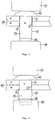
- Fig.1 successively depicts the plate-stack 10 to be joined, consisting of two (or more) plates or sheets 11 and 12, with a hole 13, being drilled therein, after the sheets 11 and 12 have been clamped together in preparation of the riveting treatment.
- a rivet 15 provided with a rivet-head 16 and a shank 17 having on its free extremity a pilot edge 18, if any.
- part 19 of the shank 17 protrudes through the plate-stack 10. From this part 19 the riveted head 20 has eventually to be formed during the riveting process.
- the rivet is placed between two rivet dies (or cup-tools): an upper rivet die 21 and a lower rivet die 22.
- an upper rivet die 21 and a lower rivet die 22.
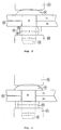
- a lower rivet die 22 In the conventional method use is made of flat punches, as shown in Fig. 1-5.
- a plate-stack 30 consisting of plates or sheets 31 and 32, in which a hole is drilled, bounded by the hole wall 29, said hole showing at its top a recess or countersink 44.
- a rivet shank 37 Into the hole is stuck a rivet shank 37, whose circumference 34 is in engagement with the hole wall 29.
- the shank 37 projects through the plate-stack 30 above and below. This gives a shank-end 35 at the upper side and a shank-end 39 at the lower side, from which during the riveting process the heads 36 and 40 resp. (Fig.8) are formed.
- an upper and lower rivet punch 41 and 42 resp. which contain a recess 45 and 46 resp..
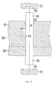
- FIG. 10-18 serve as illustration of the method according to the invention in which a rivet of the D-,S-,DD- or KE-type is used,separately illustrated in Fig.9.
- These are alloys, which have obtained, by precipitation-hardening, a high (shear) strength: more than 230 N/mm 2 .
- Fig.16-18 show the riveting joint of Fig. 13-15, but now without rivet dies 61,62.
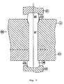
- the method is best employed by using a punch having in the central part a profile being complementary to that of the shank-end, possibly provided with a centring edge 58 (38,18), such that the die is self-centring.
- the lower rivet punch 62 has a stepped profile 70 with the parts 67,68 and 69, in which its central part 68,69 is complementary to the shape of the shank-end or the centring-edge 58 resp. of the shank 57. In this way the construction is self-centring.
Landscapes
- Engineering & Computer Science (AREA)
- Mechanical Engineering (AREA)
- Insertion Pins And Rivets (AREA)
- Connection Of Plates (AREA)
Claims (8)
- Verfahren zum Verbinden von Metallplatten (51,52) eines Stapels (50) mittels eines sich durch ein Loch (53) in dem Stapel (50) hindurcherstreckenden Niets (55), wobei der Niet einen Schenkel (57) und Schenkelenden (56;58,59) aufweist, das Verfahren mit den Verfahrensschritten:Selektieren einer Aluminiumlegierung, die eine Scherfestigkeit > 230 N/mm2 aufweist und zum Ausbilden des Niets (55) verwendet wird,Ausbilden des Niets (55) in einem nicht-lösungsgeglühten Zustand zwischen einem ersten Drückelement (62) und einem zweiten Drückelement (61), wobei das erste Drückelement einen inneren Hohlraum (66) aufweist,Anordnen der Drückelemente (61,62) zu Beginn gegen die jeweiligen Schenkelenden (56;58,59) des Niets (55),Ausüben von Kräften auf die Schenkelenden (56;58,59), so daß ein radiales Ausdehnen des Schenkelendes (59) in einen Kopf (60) hinein verursacht wird, gekennzeichnet durch die VerfahrensschritteBereitstellen des Hohlraums (66) in dem ersten Drückelement (62) mit einer abgestuften Kontur (70), die einen einen kleineren Durchmesser aufweisenden Mittelabschnitt (68,69) und einen damit über eine Stufe verbundenen, einen größeren Durchmesser aufweisenden größeren Abschnitt (67) aufweist,Anordnen des Schenkelendes (58) in dem Mittelabschnitt (68,69) des ersten Drückelements (62) und anschließendes Ausüben von Kräften auf den Schenkel (57),Anhalten des radialen Ausdehnens des Schenkelkopfes (60) in dem größeren Abschnitt (67) des Hohlraumes (66) des ersten Drückelements (62), so daß das Verhältnis eines Enddurchmessers (D) des Kopfes (60) zu einem Anfangsdurchmesser (d) des Schenkelendes (59) unterhalb eines kritischen Wertes bleibt, oberhalb dessen Bruchverformung eintritt,Ausüben von weiterem Druck auf den Kopf (60), so daß ein longitudinaler Transport von Masse entlang des Schenkels (57) eintritt, wodurch ein Durchmesser eines Lochs, in welchem sich der Niet (55) durch die Metallplatten (51,52) hindurcherstreckt, aufgrund des Ausdehnens des Schenkels (57) aufgeweitet wird.
- Verfahren nach Anspruch 1, wobei das radiale Ausdehnen des Schenkelkopfes (60) durch den größeren Abschnitt (67) des Hohraumes (66) des ersten Drückelements (62) bei einem Verhältnis D/d von 1,4 - 1,5 angehalten wird.
- Verfahren nach Anspruch 1 oder 2, wobei der Niet aus einer Aluminiumlegierung mit einer hohen Festigkeit hergestellt wird, die durch Abkühlen der Legierung infolge von Kaltaushärten in den gehärteten Zustand erzielt wird.
- Verfahren nach einem der vorangehenden Ansprüche, wobei der Mittelabschnitt (68,69) des Raumes (66) in dem ersten Drückelement (63) und das Schenkelende (58) komplementär hergestellt werden.
- Verfahren nach einem der vorangehenden Ansprüche, wobei die Aluminiumlegierung des Niets (55) aus einer ALCOA 2000 Serie mit einem der Nennwerte 2017, 2017A und 2024 selektiert wird.
- Verfahren nach einem der Ansprüche 1-4, wobei die Aluminiumlegierung aus einer ALCOA 7000 Serie mit einer minimalen Scherfestigkeit von 280 N/mm2 selektiert wird, bevorzugt mit einem Nennwert von 7050.
- Nietverbindung zwischen einem Stapel (50) von Metallplatten (51,52) mit Löchern (53) darin, wobei die Verbindung mittels Nieten (55) hergestellt ist, die sich jeweils durch ein Loch (53) hindurch erstrecken, die Nieten aus einer Aluminiumlegierung mit einer minimalen Scherfestigkeit von 230 N/mm2 hergestellt sind und in einem nicht-lösungsgeglühten Zustand verwendet werden, jeder Niet einen Kopf (56,60) an jedem Ende eines Schenkels (57) aufweist, der Stapel von Metallplatten zwischen den Köpfen eingeklammert ist, dadurch gekennzeichnet, daß wenigstens ein Kopf (60) eine abgestufte Kontur mit einem einen kleineren Durchmesser aufweisenden Mittelabschnitt und einem damit über eine Stufe verbundenen, einen größeren Durchmesser aufweisenden größeren Abschnitt (67) aufweist, wobei der Durchmesser (D) des größeren Abschnitts ca. 1,4 - 1,5 mal größer als der Durchmesser (d) des Schenkels ist.
- Drückelement zum Verwenden in einem Verfahren nach einem der Ansprüche 1-6, wobei das Drückelement einen inneren Hohlraum (66) zum Ausbilden eines Kopfes (60) an dem Ende (59) eines Schenkels (57) eines Niets (55) aufweist, dadurch gekennzeichnet, daß der Raum eine abgestufte Kontur (70) mit einem einen kleineren Durchmesser aufweisenden Mittelabschnitt (68,69) und einem damit über eine Stufe verbundenen, einen größeren Durchmesser aufweisenden größeren Abschnitt (67) aufweist.
Applications Claiming Priority (3)
| Application Number | Priority Date | Filing Date | Title |
|---|---|---|---|
| NL9100286A NL9100286A (nl) | 1991-02-19 | 1991-02-19 | Werkwijze, snapper, nagel, etc. voor het met elkaar verbinden van een platenpakket d.m.v. klinknagels uit een al-legering. |
| NL9100286 | 1991-02-19 | ||
| PCT/NL1992/000034 WO1992014566A1 (en) | 1991-02-19 | 1992-02-18 | Method, rivet-punch, rivet, etc. for joining several metal sheets by using non-heat-treating rivets made from an aluminium alloy |
Publications (2)
| Publication Number | Publication Date |
|---|---|
| EP0572513A1 EP0572513A1 (de) | 1993-12-08 |
| EP0572513B1 true EP0572513B1 (de) | 1997-12-17 |
Family
ID=19858900
Family Applications (1)
| Application Number | Title | Priority Date | Filing Date |
|---|---|---|---|
| EP92906537A Expired - Lifetime EP0572513B1 (de) | 1991-02-19 | 1992-02-18 | VERFAHREN ZUM VERBINDEN VON METALLBLECHEN MITTEL UNGEGLüHTER NIETE |
Country Status (6)
| Country | Link |
|---|---|
| US (1) | US5557835A (de) |
| EP (1) | EP0572513B1 (de) |
| CA (1) | CA2105183A1 (de) |
| DE (1) | DE69223612T2 (de) |
| NL (1) | NL9100286A (de) |
| WO (1) | WO1992014566A1 (de) |
Families Citing this family (12)
| Publication number | Priority date | Publication date | Assignee | Title |
|---|---|---|---|---|
| US6014804A (en) * | 1998-06-12 | 2000-01-18 | The Boeing Company | Low voltage electromagnetic process and apparatus for controlled riveting |
| US6363768B1 (en) * | 2000-06-20 | 2002-04-02 | Aviation Tools & Technologies International, L.L.C. | Precision bucking bar |
| CA2739635C (en) * | 2001-06-26 | 2014-03-11 | Magna Structural Systems Inc. | Method of forming a rivet using a riveting apparatus |
| US7313852B2 (en) * | 2003-12-23 | 2008-01-01 | Magna Structural Systems, Inc. | Method of forming a rivet using a riveting apparatus |
| CN102513497B (zh) * | 2011-12-13 | 2015-01-14 | 广州信邦汽车装备制造有限公司 | 用于装配平衡器的旋铆模及利用旋铆模进行铆接的方法 |
| JP5821121B2 (ja) * | 2011-12-22 | 2015-11-24 | ポップリベット・ファスナー株式会社 | 自己穿孔型リベット用ダイ |
| JP2013169567A (ja) * | 2012-02-21 | 2013-09-02 | Nippon Pop Rivets & Fasteners Ltd | 自己穿孔型リベット用ダイ |
| DE102013111584A1 (de) | 2013-10-21 | 2015-05-07 | Federal-Mogul Bremsbelag Gmbh | Trägerkörper für einen Bremsbelag einer Scheibenbremse mit Tilgermasse zur Veränderung der Schwingung |
| DE102013111594B4 (de) | 2013-10-21 | 2015-04-30 | Federal-Mogul Bremsbelag Gmbh | Verfahren zur Herstellung eines Trägerkörpers mit Tilgermasse zur Veränderung der Schwingung für einen Bremsbelag einer Scheibenbremse |
| CN104338885A (zh) * | 2014-10-29 | 2015-02-11 | 董斌 | 一种气动热铆枪枪头 |
| US10593034B2 (en) * | 2016-03-25 | 2020-03-17 | Arconic Inc. | Resistance welding fasteners, apparatus and methods for joining dissimilar materials and assessing joints made thereby |
| CN114226625B (zh) * | 2021-12-17 | 2024-03-08 | 大连长丰实业总公司 | 一种双层薄板自锁结合方法 |
Family Cites Families (8)
| Publication number | Priority date | Publication date | Assignee | Title |
|---|---|---|---|---|
| US3426641A (en) * | 1966-04-07 | 1969-02-11 | Irwin E Rosman | Fastener unit with forming die |
| US3561102A (en) * | 1968-09-25 | 1971-02-09 | Champion Commercial Ind Inc | Process of forming a cold driven riveted joint |
| US3933025A (en) * | 1974-03-28 | 1976-01-20 | Briles Franklin S | High speed riveting system |
| US3908257A (en) * | 1974-08-14 | 1975-09-30 | Franklin S Briles | Go, No-go rivet gun |
| US3952401A (en) * | 1975-06-30 | 1976-04-27 | The Boeing Company | Process for installing fatigue-rated rivets |
| US4630463A (en) * | 1984-11-28 | 1986-12-23 | The Boeing Company | Rivet driving die and method |
| US4864713A (en) * | 1988-06-07 | 1989-09-12 | Gemcor Engineering Corp. | Method and apparatus for positioning tooling and riveting |
| US5060362A (en) * | 1990-07-10 | 1991-10-29 | Gemcor Engineering Corp. | Slug riveting method and apparatus with C-frame deflection compensation |
-
1991
- 1991-02-19 NL NL9100286A patent/NL9100286A/nl not_active Application Discontinuation
-
1992
- 1992-02-18 EP EP92906537A patent/EP0572513B1/de not_active Expired - Lifetime
- 1992-02-18 WO PCT/NL1992/000034 patent/WO1992014566A1/en not_active Ceased
- 1992-02-18 US US08/107,705 patent/US5557835A/en not_active Expired - Fee Related
- 1992-02-18 CA CA002105183A patent/CA2105183A1/en not_active Abandoned
- 1992-02-18 DE DE69223612T patent/DE69223612T2/de not_active Expired - Fee Related
Also Published As
| Publication number | Publication date |
|---|---|
| NL9100286A (nl) | 1992-09-16 |
| US5557835A (en) | 1996-09-24 |
| DE69223612D1 (de) | 1998-01-29 |
| EP0572513A1 (de) | 1993-12-08 |
| DE69223612T2 (de) | 1998-07-23 |
| CA2105183A1 (en) | 1992-08-20 |
| WO1992014566A1 (en) | 1992-09-03 |
Similar Documents
| Publication | Publication Date | Title |
|---|---|---|
| US7052778B2 (en) | Method and apparatus for cold forging a trailer hitch receiving housing | |
| US3657957A (en) | Rivet | |
| EP0572513B1 (de) | VERFAHREN ZUM VERBINDEN VON METALLBLECHEN MITTEL UNGEGLüHTER NIETE | |
| JP5184482B2 (ja) | ねじ付きブラインドインサートの製造方法 | |
| EP1504197B1 (de) | Bolzen mit ziehnuten für angestauchte kragen | |
| US4472096A (en) | Optimized fastener construction system and method | |
| US3253495A (en) | Hardened blind bolt with annealed shank portion | |
| US3365926A (en) | Manufacture of plate metal parts with integral threaded fasteners | |
| EP1141560A1 (de) | Blindbefestiger | |
| EP2078165B1 (de) | Befestigungssystem mit niedriger umformlast | |
| EP1623126B1 (de) | Blindbefestiger und verfahren zur dessen entfernung von einem werkstück | |
| US7461533B2 (en) | Forging method forged product and forging apparatus | |
| US4324518A (en) | Dish compensating flush head fastener | |
| US3953906A (en) | Fastener assembly | |
| US5299441A (en) | Method of making a mandrel comprising a drill section for a self-drilling blind rivet | |
| WO2016113254A1 (en) | Method for producing a closed-end blind rivet, and closed-end blind rivet | |
| AU2006249212B2 (en) | Method of manufacturing a blind threaded insert | |
| ZA200507051B (en) | Blind fastener and method of removing it from a workpiece | |
| HK1001086A1 (en) | Method of making a mandrel comprising a drill section |
Legal Events
| Date | Code | Title | Description |
|---|---|---|---|
| PUAI | Public reference made under article 153(3) epc to a published international application that has entered the european phase |
Free format text: ORIGINAL CODE: 0009012 |
|
| 17P | Request for examination filed |
Effective date: 19930726 |
|
| AK | Designated contracting states |
Kind code of ref document: A1 Designated state(s): BE DE ES FR GB IT NL SE |
|
| 17Q | First examination report despatched |
Effective date: 19940124 |
|
| GRAG | Despatch of communication of intention to grant |
Free format text: ORIGINAL CODE: EPIDOS AGRA |
|
| GRAG | Despatch of communication of intention to grant |
Free format text: ORIGINAL CODE: EPIDOS AGRA |
|
| GRAH | Despatch of communication of intention to grant a patent |
Free format text: ORIGINAL CODE: EPIDOS IGRA |
|
| GRAH | Despatch of communication of intention to grant a patent |
Free format text: ORIGINAL CODE: EPIDOS IGRA |
|
| GRAA | (expected) grant |
Free format text: ORIGINAL CODE: 0009210 |
|
| AK | Designated contracting states |
Kind code of ref document: B1 Designated state(s): BE DE ES FR GB IT NL SE |
|
| PG25 | Lapsed in a contracting state [announced via postgrant information from national office to epo] |
Ref country code: IT Free format text: LAPSE BECAUSE OF FAILURE TO SUBMIT A TRANSLATION OF THE DESCRIPTION OR TO PAY THE FEE WITHIN THE PRE;WARNING: LAPSES OF ITALIAN PATENTS WITH EFFECTIVE DATE BEFORE 2007 MAY HAVE OCCURRED AT ANY TIME BEFORE 2007. THE CORRECT EFFECTIVE DATE MAY BE DIFFERENT FROM THE ONE RECORDED.SCRIBED TIME-LIMIT Effective date: 19971217 Ref country code: ES Free format text: THE PATENT HAS BEEN ANNULLED BY A DECISION OF A NATIONAL AUTHORITY Effective date: 19971217 |
|
| REF | Corresponds to: |
Ref document number: 69223612 Country of ref document: DE Date of ref document: 19980129 |
|
| PG25 | Lapsed in a contracting state [announced via postgrant information from national office to epo] |
Ref country code: SE Free format text: LAPSE BECAUSE OF FAILURE TO SUBMIT A TRANSLATION OF THE DESCRIPTION OR TO PAY THE FEE WITHIN THE PRESCRIBED TIME-LIMIT Effective date: 19980317 |
|
| ET | Fr: translation filed | ||
| PLBE | No opposition filed within time limit |
Free format text: ORIGINAL CODE: 0009261 |
|
| STAA | Information on the status of an ep patent application or granted ep patent |
Free format text: STATUS: NO OPPOSITION FILED WITHIN TIME LIMIT |
|
| 26N | No opposition filed | ||
| PGFP | Annual fee paid to national office [announced via postgrant information from national office to epo] |
Ref country code: GB Payment date: 19990218 Year of fee payment: 8 |
|
| PGFP | Annual fee paid to national office [announced via postgrant information from national office to epo] |
Ref country code: BE Payment date: 19990224 Year of fee payment: 8 |
|
| PGFP | Annual fee paid to national office [announced via postgrant information from national office to epo] |
Ref country code: NL Payment date: 19990228 Year of fee payment: 8 |
|
| PGFP | Annual fee paid to national office [announced via postgrant information from national office to epo] |
Ref country code: DE Payment date: 19990430 Year of fee payment: 8 |
|
| PG25 | Lapsed in a contracting state [announced via postgrant information from national office to epo] |
Ref country code: GB Free format text: LAPSE BECAUSE OF NON-PAYMENT OF DUE FEES Effective date: 20000218 |
|
| PG25 | Lapsed in a contracting state [announced via postgrant information from national office to epo] |
Ref country code: BE Free format text: LAPSE BECAUSE OF NON-PAYMENT OF DUE FEES Effective date: 20000228 |
|
| BERE | Be: lapsed |
Owner name: BRANDTS MICHIEL PIETER Effective date: 20000228 |
|
| PG25 | Lapsed in a contracting state [announced via postgrant information from national office to epo] |
Ref country code: NL Free format text: LAPSE BECAUSE OF NON-PAYMENT OF DUE FEES Effective date: 20000901 |
|
| GBPC | Gb: european patent ceased through non-payment of renewal fee |
Effective date: 20000218 |
|
| NLV4 | Nl: lapsed or anulled due to non-payment of the annual fee |
Effective date: 20000901 |
|
| PG25 | Lapsed in a contracting state [announced via postgrant information from national office to epo] |
Ref country code: DE Free format text: LAPSE BECAUSE OF NON-PAYMENT OF DUE FEES Effective date: 20001201 |
|
| REG | Reference to a national code |
Ref country code: FR Ref legal event code: ST |
|
| REG | Reference to a national code |
Ref country code: FR Ref legal event code: RN |
|
| REG | Reference to a national code |
Ref country code: FR Ref legal event code: FC |
|
| PGFP | Annual fee paid to national office [announced via postgrant information from national office to epo] |
Ref country code: FR Payment date: 20020828 Year of fee payment: 11 |
|
| PG25 | Lapsed in a contracting state [announced via postgrant information from national office to epo] |
Ref country code: FR Free format text: LAPSE BECAUSE OF NON-PAYMENT OF DUE FEES Effective date: 20031031 |
|
| REG | Reference to a national code |
Ref country code: FR Ref legal event code: ST |