EP0572705B1 - Procédé et dispositif pour la production d'extraits de couleur d'un modèle en plusieurs couleurs - Google Patents
Procédé et dispositif pour la production d'extraits de couleur d'un modèle en plusieurs couleurs Download PDFInfo
- Publication number
- EP0572705B1 EP0572705B1 EP92109556A EP92109556A EP0572705B1 EP 0572705 B1 EP0572705 B1 EP 0572705B1 EP 92109556 A EP92109556 A EP 92109556A EP 92109556 A EP92109556 A EP 92109556A EP 0572705 B1 EP0572705 B1 EP 0572705B1
- Authority
- EP
- European Patent Office
- Prior art keywords
- colour
- color
- signal values
- space
- correction
- Prior art date
- Legal status (The legal status is an assumption and is not a legal conclusion. Google has not performed a legal analysis and makes no representation as to the accuracy of the status listed.)
- Expired - Lifetime
Links
- 238000000034 method Methods 0.000 title claims abstract description 37
- 238000000926 separation method Methods 0.000 title claims abstract description 23
- 238000012937 correction Methods 0.000 claims abstract description 38
- 239000003086 colorant Substances 0.000 claims abstract description 35
- 230000008569 process Effects 0.000 claims abstract description 16
- 230000006735 deficit Effects 0.000 claims description 5
- 230000015572 biosynthetic process Effects 0.000 claims description 2
- 238000013500 data storage Methods 0.000 claims description 2
- 230000006870 function Effects 0.000 claims description 2
- 238000004519 manufacturing process Methods 0.000 claims description 2
- 239000011159 matrix material Substances 0.000 claims 1
- 238000003860 storage Methods 0.000 abstract description 7
- 238000012545 processing Methods 0.000 description 6
- 239000000976 ink Substances 0.000 description 5
- 238000005070 sampling Methods 0.000 description 5
- 230000003287 optical effect Effects 0.000 description 4
- 238000012546 transfer Methods 0.000 description 4
- 239000013598 vector Substances 0.000 description 4
- 238000010586 diagram Methods 0.000 description 3
- 239000013307 optical fiber Substances 0.000 description 3
- 230000008859 change Effects 0.000 description 2
- 230000008030 elimination Effects 0.000 description 2
- 238000003379 elimination reaction Methods 0.000 description 2
- 238000009499 grossing Methods 0.000 description 2
- 230000033458 reproduction Effects 0.000 description 2
- 239000004753 textile Substances 0.000 description 2
- 230000007704 transition Effects 0.000 description 2
- 238000012952 Resampling Methods 0.000 description 1
- 230000006978 adaptation Effects 0.000 description 1
- 238000013459 approach Methods 0.000 description 1
- 230000008901 benefit Effects 0.000 description 1
- 230000002457 bidirectional effect Effects 0.000 description 1
- 230000005540 biological transmission Effects 0.000 description 1
- 239000000969 carrier Substances 0.000 description 1
- 238000004040 coloring Methods 0.000 description 1
- 238000004891 communication Methods 0.000 description 1
- 230000003247 decreasing effect Effects 0.000 description 1
- 238000013461 design Methods 0.000 description 1
- 238000011161 development Methods 0.000 description 1
- 238000009826 distribution Methods 0.000 description 1
- 230000009977 dual effect Effects 0.000 description 1
- 239000004744 fabric Substances 0.000 description 1
- 238000001914 filtration Methods 0.000 description 1
- 230000001771 impaired effect Effects 0.000 description 1
- 238000012544 monitoring process Methods 0.000 description 1
- 230000005693 optoelectronics Effects 0.000 description 1
- 230000009467 reduction Effects 0.000 description 1
- 230000001960 triggered effect Effects 0.000 description 1
- 230000000007 visual effect Effects 0.000 description 1
- 229910052724 xenon Inorganic materials 0.000 description 1
- FHNFHKCVQCLJFQ-UHFFFAOYSA-N xenon atom Chemical compound [Xe] FHNFHKCVQCLJFQ-UHFFFAOYSA-N 0.000 description 1
Images



Classifications
-
- H—ELECTRICITY
- H04—ELECTRIC COMMUNICATION TECHNIQUE
- H04N—PICTORIAL COMMUNICATION, e.g. TELEVISION
- H04N1/00—Scanning, transmission or reproduction of documents or the like, e.g. facsimile transmission; Details thereof
- H04N1/46—Colour picture communication systems
- H04N1/56—Processing of colour picture signals
- H04N1/60—Colour correction or control
- H04N1/62—Retouching, i.e. modification of isolated colours only or in isolated picture areas only
- H04N1/622—Retouching, i.e. modification of isolated colours only or in isolated picture areas only with simulation on a subsidiary picture reproducer
-
- G—PHYSICS
- G01—MEASURING; TESTING
- G01J—MEASUREMENT OF INTENSITY, VELOCITY, SPECTRAL CONTENT, POLARISATION, PHASE OR PULSE CHARACTERISTICS OF INFRARED, VISIBLE OR ULTRAVIOLET LIGHT; COLORIMETRY; RADIATION PYROMETRY
- G01J3/00—Spectrometry; Spectrophotometry; Monochromators; Measuring colours
- G01J3/46—Measurement of colour; Colour measuring devices, e.g. colorimeters
- G01J3/50—Measurement of colour; Colour measuring devices, e.g. colorimeters using electric radiation detectors
-
- G—PHYSICS
- G01—MEASURING; TESTING
- G01J—MEASUREMENT OF INTENSITY, VELOCITY, SPECTRAL CONTENT, POLARISATION, PHASE OR PULSE CHARACTERISTICS OF INFRARED, VISIBLE OR ULTRAVIOLET LIGHT; COLORIMETRY; RADIATION PYROMETRY
- G01J3/00—Spectrometry; Spectrophotometry; Monochromators; Measuring colours
- G01J3/46—Measurement of colour; Colour measuring devices, e.g. colorimeters
- G01J3/462—Computing operations in or between colour spaces; Colour management systems
Definitions
- the invention is in the field of computer-controlled processing of colored sample templates, for example textile sample templates, and relates in particular to a method and an apparatus for producing color separations from a multi-colored sample template, in particular for single-color printing.
- DE-A3 922 176 discloses a generic method for producing color separations from a multicolor sample, in particular for single-color printing, in which the sample is scanned polychromatically at points in order to obtain color signal values lying in a color space, which are used to form the Color separations are used, a predetermined number of color signal values being selected in order to obtain a correction color space, the pattern template is polychromatically scanned a second time point by point, and the color signal values obtained in this way are replaced by the color signal values of the correction color space located in the same place.
- each color to be printed is mixed before the printing process in single color printing and then transferred separately to the printing medium, so that a corresponding color separation must be produced for each color of a template.
- each color signal value for a sampling point can be composed of three or even more color components, for example for the colors red, green and blue, which are measured with the aid of color-sensitive detectors.
- the template contains a very large number of different colors, a correspondingly high number of color separations must be created. This is undesirable for practical reasons, especially since a special printing form must also be produced for each color separation.
- the color components must be saved for each sample point of the original, which requires a large storage capacity due to the enormous amount of data.
- the invention has for its object, on the one hand, to be able to reproduce a template with a significantly reduced number of color separations compared to the number of its colors, without having to accept significant impairments with regard to the color fidelity and the liveliness of the template.
- a suitable device for performing the method is to be created.
- z. B three color components (red, green, blue) are measured, which define a color signal value lying in the color space (RGB space).
- RGB space color space
- different color signal values are obtained which are at different positions in the color space.
- the position of a color signal value is obtained by vectorial addition of the measured color components that have previously been converted into digital values.
- color signal values are obtained which are assigned to the same position in the color space.
- a desired number of color signal values that have occurred most frequently can therefore be selected, these color signal values being stored in a table which can also be referred to as a color palette.
- This color palette is continuously addressed and therefore contains one of the most frequently occurring color signal values under each address. For example, 240 of the most frequently occurring color signal values can be stored in this color palette. Another 16 color signal values can be stored for system purposes, as will be explained.
- the previously mentioned color space which is not yet completely filled with color signal values, is then filled with the most frequently occurring color signal values in order to obtain a correction color space. Both positions of the color space that have not yet been occupied are described with the most frequently occurring color signal values as also those positions for which color signal values have previously been obtained that do not belong to the most frequently occurring color signal values.
- the correction color space can be formed in such a way that the positions or addresses of the previously obtained color space are assigned to that of the most frequently occurring color signal values from which they have the smallest topological distance in the color space. If a position to be occupied lies exactly between two signal values that belong to the most frequent, this position is occupied with the color signal value that has occurred more frequently than the other. If both occur equally often, one of the two is used.
- the physiological distances can also be used, for which purpose only the color signal values need to be logarithmized beforehand.
- the assignment of the color space with the most frequently occurring color signal values means nothing other than that an address of the color palette is assigned to each position of the color space.
- the correction color space therefore only contains addresses of the color palette.
- the addresses of the color palette e.g. 256 addresses
- the template is now point by point a second time polychromatic or trichromatic scanned, again along adjacent rows or columns.
- z. B the intensity of the color components (red, green, blue) measured and these measured values converted into digital values in order to be able to address the correction color space in this way by vectorial addition of the color components.
- the address obtained is an address of the aforementioned address table, an address of the color palette being stored under this address, under which in turn a color signal value (one of the most frequently occurring) is stored.
- the sample is scanned point-by-point along columns or rows for the second time, only the address of the color palette that has been visited needs to be saved for each pixel, so that a string or a chain of color palette addresses is recorded for each pattern picture.
- the replacement of the color signal values obtained in the second scan by the color signal values of the correction color space located at the same place is thus carried out via the addressing of the address table and the subsequent addressing of the color palette. Since in addition to the address table only the color palette has to be stored and the string only stores the addresses of the color palette, only relatively little storage space is required for storing the pattern image information compared to the case in which the color signal value is to be stored for each pixel of the pattern image.
- the selection of a desired number of the most frequently occurring color signal values, the filling in of the color space with these color signal values and the resampling of the sample image also ensure that the pattern can be reproduced true to color and without impairing the vividness.
- the color separations can then be generated in a simple manner from the string obtained by reading the different color palette addresses from it in a correct position. In this way, the color separations are outsourced, for example to developable black and white films or to magnetic data carriers, or the like.
- the size of pixels of the color separations can also correspond to the relative proportion of the selected color used, which means that the larger the color intensity, the larger the pixel is.
- the template will be scanned in a finer geometric grid during the second scan than during the first scan. In other words, the scanning light points are closer together than in the first scanning. You can even overlap. This enables reproductions of the sample image that are very true to color to be produced, only the length of the string of the color palette addresses being increased. In comparison to the storage of the color signal values for each of the sampling points, this represents only an insignificant increase in the storage capacity.
- the size of the sampling light point on the template can be selected depending on the pattern structure, for. B. depending on their roughness. In any case, the scanning light spot should be so large that sufficient light is still reflected on the original.
- the sample image is reproduced in a further step only using the color signal values of the correction color space obtained after the second sampling, in order then to select a number of predetermined colors on the basis of the reproduced sample image.
- the color signal values of the correction color space are then replaced by the color signal values corresponding to these selected colors.
- each color signal value of the correction color space being replaced by one of a selected color from which it has the smallest topological distance in the correction color space.
- the physiological distance can replace the topological distance.
- the addresses of the color palette stored under the addresses of the address table are changed and the address table was driven in the same way as was the case with the second scan.
- a device for carrying out the method according to the invention has a plurality of transputer units, each transputer unit being assigned a separate magnetic hard disk for data storage.
- the transputer units are connected to a common data bus, via which the pattern data from e.g. B. sent to a scanner.
- transputer units are each coupled via a common bus to a transputer with a large image monitor for the overall image output and operating function display and to another transputer with a large image monitor for the detail image output.
- a common computer with a screen as the operator interface is preferably assigned to the transputer units.
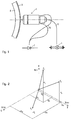
- Fig. 1 shows an optical scanning system with an optical scanning head 1 for scanning a template attached to a rotating cylinder 2 3.
- the template can, for. B. be a textile template, e.g. B. a fabric, a carpet, and the like, a paper template, etc.
- White light from a light source 4 passes into an optical fiber 5 in order to be able to illuminate the pattern template 3 with this light.
- the light source 4 can be a high-pressure xenon lamp, for example.
- reflected light is collected on the template 3 and transmitted to a photodetector arrangement 7 which has color-selective properties.
- the scanning frequency during the pattern scanning, the movement path of the optical scanning head, the position of the template 3 on the cylinder 2 and the rotational speed of the Cylinder 2 predefined or saved.
- the template 3 is first clamped onto the cylinder 2. It is then point-lit with white light from the light source 4. The pattern template 3 is first scanned in a rough geometric grid and is used to determine which colors occur and in which frequency.
- the light reflected by the template 3 is collected via the optical fibers 7, the intensity of the reflected light in 3 wavelength ranges is measured, with the help of the photodetector arrangement 7 already mentioned.
- the measured values are subsequently converted into digital values, which are referred to as color components.
- the first wavelength range lies between 420 and 480 nm and corresponds to the color blue
- the second wavelength range lies between 480 and 570 nm and corresponds to the color green
- the third wavelength range lies between 570 and 650 nm and corresponds to the color red.
- each color point of the template 3 is entered in a three-dimensional scale of 32,768 colors.
- This scale is referred to below as the color space or RGB color space.
- the named color space is sketched in Fig. 2.
- the colors F1, F2 and F3 mentioned each consist of color components r1, g1, b1; r2, g2, b2; r3, g3, b3 together, i.e. from three measured color components for the colors red, green and blue.
- a cell is obtained at the end of one of the vectors, which is addressed by the associated color components of the vector.
- the color space is now reduced to 240 colors in accordance with the frequency of the color signal values of the template 3.
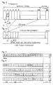
- This table is shown in FIG. 3 and is referred to below as the color palette.
- 16 colors are needed for system purposes.
- B. for coloring edges and control panels on a monitor, so that a maximum of 240 addresses remain for the measured color signal values.
- Each of the addresses of the color palette shown in FIG. 3 comprises a memory area of 2 bytes, so that a color signal value can be accommodated, which consists of 3 ⁇ 5 bits, 5 bits (color component) being required for the 32 intensity levels mentioned.
- a correction color space is now developed from the color space shown in FIG. 2, and only using the 240 color signal values stored in the color palette. In other words, the remaining cells of the color space are occupied by these 240 color signal values.
- the address of each cell of the correction color space corresponds to that of the corresponding cell of the previously obtained color space, but the cell content corresponds to the number or address of that color signal value of the color palette to which the cell of the color space has the smallest topological distance. Instead, the number or address of that color signal value of the color palette to which the smallest physiological distance is determined could also be entered. This measure essentially amounts to a logarithmic distortion of the color space.
- Each address of the color space address table in Fig. 4 includes a 1 byte memory area to store one of the 240 addresses in the color palette.
- the scanning light spots are now closer together than in the first scanning and can also overlap.
- the size of the scanning light spot is selected depending on the pattern structure and can, for. B. 70 »m (diameter on the template).
- the color components now received for each pixel address a cell in the correction color space or an address in the color space address table.
- the assigned address of the color palette is stored under this address and is now stored in a third table for the pixel currently being scanned, which is shown in FIG. 5.
- the address 240 of the color palette is subsequently stored in the third table shown in FIG. 5 as the first storage value. This process is repeated until the entire template 3 has been scanned. Will she z. B. scanned with the help of 1 million pixels, the third table in Fig. 5 has 106 memory locations in which there are addresses of the color palette. This third table can be saved on a hard disk.
- color separations can then be distilled from the third table by creating the further tables shown in FIG. 6, in which only the same addresses of the color palette are contained. The location of these addresses in the other tables corresponds to their location in the third table.
- the sample image 3 can instead be displayed in a further step on a large screen in order to be able to examine it. Three to eight and in special cases up to 52 printing colors can be defined.
- the palette color tone recorded for each pattern point is then assigned to one of the defined printing colors, which in turn takes place by appropriately re-assigning the cells of the correction color space, in the manner already described above. If you choose z. B. six printing inks from the 240 colors of the color palette, so there are only six color vectors in the correction color space, so that the remaining cells of the correction color space in the same way as described above are again occupied with the color palette addresses of these six selected printing colors. In other words, only these six color palette addresses appear under the addresses of the color space address table in FIG. 4.
- the color distribution shown in the second column is yellow, yellow, yellow, red, yellow, yellow, red, red, red, yellow, red.
- the balances can also be included multiplied by a selectable memory factor that is less than 1, with each new color point. The multiplication by the memory factor is done for the purpose of suppressing only slightly containing color components, the very rare sudden occurrence of which would be rather annoying, especially when a color tone slowly fades away.
- the sample image thus calculated and output on the screen is inspected again and, if necessary, corrected in a further alternative step.
- This filtering process can consist of blurring or smearing, hardening of the color sequence or increasing the color gradient, pixel elimination or edge smoothing.
- blurring the steepness of the course of the RGB components is reduced and at the same time the smaller values of the RGB components are increased and the larger of these values are decreased.
- the reverse process is selected when the color gradient hardens.
- pixel elimination the RGB components of very small structures are replaced by those in the environment.
- the areas with the steepest RGB sequences which are in jagged form, are vectorized in a selected area of the pattern points and an equally steep and equally directed RGB sequence is placed in the straight connection between the start and end points.
- the size of the z. B. screen dots to be output on a film determined. The greater the intensity, the greater the grid point.
- another data carrier for immediate further processing e.g. B. find use on numerically controlled engraving systems.
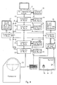
- FIGS. 8 to 10 show the embodiment of the invention in terms of the device, for example.
- a key feature is the use of two large screens.
- One of these two monitors is used to display the overview of the template, shows the operating menu and also has space for dialog input and output.
- the other large screen is used to display a section of the template to be edited. This has the advantage that all the sample data and information required for processing are visually available at the same time.
- 21 denotes the PC-compatible computer with its input screen, which serves as an operating system for the downstream part of the system. This is also provided as a file server for the optical hard disk 22, which stores the finished processed sample data.
- the downstream system part essentially consists of a plurality of transputers 23.
- Each of these transputers 23 consists of a central processor unit, which is equipped with a floating point processor and a memory unit on the same chip. There is a 32 Mbyte RAM on the same board.
- Each of these transputers 23 is assigned its own magnetic hard disk 24 with a memory area of 768 Mbytes. For example, four such units are used.
- the individual transputers 23 to have the pattern read line by line from the pattern template by means of a color scanner 25 in groups, each comprising a large number of lines.
- the hard disk 24 is assigned to each transputer 23 as a medium for the temporary amounts of data that arise during processing.
- the entirety of the pattern data is accordingly divided in parallel onto a plurality of hard disks 24 and also processed in parallel by the transputers 23.
- the detail monitor 26 and the overview monitor 27 serve to illustrate the processing status.
- the detail monitor 26 is controlled by the video transputer 28 and the overview monitor 27 by the video transputer 29.
- the transputers 23 are connected to one another via very fast serial bidirectional data transfer lines 31, also called computer links.
- the data transmission from and to the hard disks 24 is carried out via an 8 bit wide parallel bus line 32.
- This last-mentioned bus line 32 is routed separately between each transputer 23 and the associated hard disk 24. This means that the data transfer between each transputer 23 and its hard disk 24 can be handled in such a way that the traffic of all other transputers 23 and their hard disks 24 is not impaired and can thus be carried out as quickly as possible.
- the video transputer 28 has the task of transmitting the data of the current template section to the detail monitor 26. For this purpose it is equipped with a 32 Mbyte RAM. In addition, he is responsible for processing the input data from the keyboard 33 and also from the digitizer 34. So that this is released from the monitoring of the input devices keyboard 33 and digitizer 34, an independent microprocessor control card 30 is provided, which continuously monitors whether and from where data is being input.
- This microprocessor control card 30 is equipped with a dual-ported RAM so that data can be entered into the memory area of this card 30 or read from this memory area by both the transputer 28 and the microprocessor provided on the same card 30.
- the microprocessor control card 30 uses a single-chip processor to continuously process the current values, in particular those from the digitizing tablet 34.
- the processor evaluates each movement of a mouse 35 on the digitizer and transfers the data determined in this way to an asynchronous, dual-ported communication memory via its first port.
- the transputer 28 accesses this data via its second port and can thus process it further with maximum data throughput, that is to say with the least loss of time.
- a comparatively low data throughput is sufficient for the traffic between the single-chip processor and digitizer 34.
- the image section shown in the detail monitor 26 can be shifted by passing an inner edge line 36 and moving the mouse 35 to an outermost edge line 37 on the digitizer 34. This shifting happens the faster the closer the mouse 35 is brought to the outermost edge line 37.
- 23 again designates a transputer which loads the pattern data via a bus 48 into a 4 Mbyte (2,048 x 2,048 byte) video RAM 45.
- a pixel area which is 1,024 x 768 bytes in size and corresponds to the display area of the monitor, is created from this RAM 45 via a graphics processor 39 and sent via the RGB lines 40 to the monitor, which is no longer shown here.
- the above-mentioned video RAM 45 must be loaded with sample data from the transputer 23 via the bus line 48.
- the zoom factor is written into the ZOOM register 50 by the transputer 23.
- a settable column register 43 receives a start address which indicates the column from which the pattern stored in the video RAM 45 can be read out on the monitor.
- the column register 43 is reset in each case by a Vsync pulse, that is to say on each frame rewind or after a complete frame has been output.
- a settable line counter 44 receives the start address for the line from the transputer 23. More precisely, this line counter 44 consists of two registers, a register which keeps the start address at all times and a counter which is set to the start value stored in the first register by the Vsync pulse and by each Hsync pulse at the end of each line is decremented. However, this process undergoes a change if a zoom factor different from one has been written into the zoom register 50.
- the video RAM 45 consists of a series of RAM modules, each of which also contains a shift register (parallel in-serial out) on the same chip. This video RAM 45 can be thought of as being constructed in such a way that all these shift registers are combined to form a large shift register, in which a complete series of patterns is entered immediately when the control logic 51 issues the command to read out a line to the video RAM 45 .
- the zoom logic now calls 46 pixels by pixel from this shift register, but multiplies each of these pixels with the zoom factor and then sends them via the bus 52 to the graphics processor 39.
- the pixels thus transmitted contain not yet the color values, but these are addresses that are one byte (ie from 1 to 256) long and that refer to a table that was previously referred to as the color palette (FIG. 3).
- This color palette has been written into the 3 x 256 byte RAM available in the graphics processor 39 on the chip, specifically at the beginning of the working process.
- the colors (or color signal values) with their exact RGB components are now in this RAM under each of the possible addresses. This information is corrected by the graphics processor 39 and converted by it into analog RGB values, which are then output on the RGB lines 40.
- the device can also be used to move the screen section displayed on the monitor 26 over a substantially larger selectable memory area in terms of hardware.
- the start address in the column register 43 or that in the line counter 44 needs to be incremented or decremented, this process being triggered by the transputer 23. This is exactly the process that takes place when the mouse 35 approaches the edge of the digitizer 34.
- the quick movement of the image on the screen achieved with this is very advantageous. But it was only made possible by the much larger design of the video memory 45.
- the transputer 23 reload the pattern data into the video RAM 45. This is made possible by the internal structure of the video RAM 45 described above. It has already been mentioned that a line of the pattern is first transferred to a shift register when it is read out of the actual memory cells and only then arrives at the graphics processor 39 from there. The Reading into the shift register takes place in a very short time because it is loaded in parallel. A comparatively large time range is therefore available for the loading of the video RAM 45 by the transputer 23 via the bus line 48, specifically between the read-out processes of two individual series of samples. So that this can be done easily, the video RAM 45 must be designed as a dual ported RAM.
- the transputer unit 23 contains an adaptation logic 54 for the compatibility of the hard disk logic 55 with the transputer module 53 and an extensive dynamic RAM 56 of a total of 32 Mbytes.
- the hard disk logic 55 accesses the hard disk 24 via an 8 bit wide data bus 58.
- the rest of the data transfer within the transputer unit 23 runs over a 32 bit wide data channel 57.
- the hard disk control logic 55 reads or writes the necessary data from or to the hard disk 24 and interacts with the dynamic RAM 56 in direct memory access mode, bypassing the transputer module 53.
Landscapes
- Physics & Mathematics (AREA)
- Spectroscopy & Molecular Physics (AREA)
- Engineering & Computer Science (AREA)
- Multimedia (AREA)
- Signal Processing (AREA)
- General Physics & Mathematics (AREA)
- Image Processing (AREA)
- Spectrometry And Color Measurement (AREA)
- Color Image Communication Systems (AREA)
- Color Television Image Signal Generators (AREA)
- Crystals, And After-Treatments Of Crystals (AREA)
Claims (18)
- Procédé de production d'extraits de couleur à partir d'un modèle (3) polychrome, en particulier pour l'impression par couleur individuelle, dans lequel le modèle (3) est exploré de façon polychromatique point par point, afin d'obtenir des valeurs de signaux de couleur (F1, F2, F3) situées dans un système de couleurs (RGB), ces signaux étant utilisés pour constituer des extraits de couleur, un nombre prédéterminé de valeurs de signaux de couleur étant collecté pour obtenir un système de couleurs de correction, le modèle (3) étant exploré une deuxième fois de façon polychromatique point par point et les valeurs de signaux de couleur alors obtenues étant remplacées par les valeurs de signaux de couleur situées au même endroit du système de couleurs de correction,
caractérisé en ce que- un nombre prédéterminé de valeurs de signaux de couleur se produisant le plus fréquemment est collecté, pour constituer le système de couleurs de correction,- la collecte est effectuée automatiquement, et- le modèle (3) est exploré lors de la deuxième exploration, suivant un balayage géométrique plus fin que celui qui est utilisé lors de la première exploration. - Procédé selon la revendication 1, caractérisé en ce que :- le modèle (3) est reproduit lors d'une étape supplémentaire en utilisant seulement les valeurs de signaux de couleur du système de couleurs de correction, obtenues lors de la deuxième exploration,- un nombre de couleurs prédéterminé est choisi à l'aide du modèle reproduit, et- les valeurs de signaux de couleur du système de couleurs de correction sont remplacées par les valeurs de signaux de couleur correspondant à ces couleurs sélectionnées.
- Procédé selon la revendication 1, caractérisé en ce que pour former le système de couleurs de correction, on utilise des adresses du système de couleurs présentant celle des valeurs de signaux de couleurs les plus fréquentes avec laquelle la distance topologique est minimale.
- Procédé selon la revendication 2, caractérisé en ce qu'une valeur de signal de couleur du système de couleurs de correction est remplacée par une couleur choisie de telle sorte que la distance topologique dans le système de couleurs de correction soit minimale entre la valeur de signal de couleur du système de correction de couleurs et la couleur choisie.
- Procédé selon la revendication 3 ou 4, caractérisé en ce qu'au lieu des distances topologiques on utilise les distances physiologiques.
- Procédé selon l'une des revendications 2 ou 5, caractérisé en ce que, en cas de remplacement des valeurs de signaux de couleur du système de couleurs de correction par l'une des couleurs sélectionnées, les excès ou les insuffisances des composantes de couleur (rouge, vert, bleu) des deux couleurs les plus proches sont additionnés adresse par adresse, et en ce que, lors de l'atteinte d'une valeur de seuil de signal de couleur, pour chacune de ces couleurs sélectionnées, sa valeur de signal de couleur est utilisée pour la formation du point du modèle et notamment en calculant les composantes de couleurs de cette valeur de signal de couleur avec les composantes de couleurs obtenues par sommation jusque là.
- Procédé selon la revendication 6, caractérisé en ce que les excès ou les insuffisances constatés après placement d'un point spécifique du modèle sont multipliés par un facteur mémoire inférieur à 1.
- Procédé selon l'une des revendications 1 à 7, caractérisé en ce que le transfert des extraits de couleur s'effectue sur des films noir et blanc développables.
- Procédé selon l'une des revendications 1 à 7, caractérisé en ce que le transfert des extraits de couleur s'effectue sur un support de données magnétique.
- Procédé selon l'une des revendications 2 à 9, caractérisé en ce que la taille des points image des extraits de couleur correspond à la proportion relative de la couleur sélectionnée utilisée.
- Procédé selon l'une des revendications 1 à 10, caractérisé en ce que, lors de l'exploration point par point, les composantes de couleur sont mesurées séparément, en respectant la fidélité en intensité, et sont converties en valeurs numériques.
- Procédé selon la revendication 11, caractérisé en ce que, lors de l'exploration point par point, on effectue chaque fois la mesure de trois composantes de couleurs, de manière à effectuer une exploration tri-chromatique.
- Procédé selon la revendication 12, caractérisé en ce que pour chaque point d'exploration on mesure les composantes de couleur pour le rouge, le vert et le bleu.
- Procédé selon la revendication 12 ou 13, caractérisé en ce qu'on adresse, par trois composantes de couleurs mesurées, chaque cellule dans le système de couleurs (RGB) ou dans le système de couleurs de correction et en ce que l'on inscrit dans chaque cellule une adresse d'une palette de couleurs, adresse dans laquelle l'une des valeurs de signal de couleur rencontrées le plus fréquemment ou la valeur de signal de couleur d'une couleur sélectionnée est stockée en mémoire.
- Procédé selon la revendication 14, caractérisé en ce que l'information de couleur d'une image à modèle (3) est stockée sous forme d'une chaîne d'adresses de palettes de couleurs.
- Procédé selon la revendication 15, caractérisé en ce que cette chaîne d'adresses de palettes de couleurs est subdivisée, pour produire les extraits de couleur, en un nombre de chaînes correspondant au nombre des différentes adresses de palettes de couleurs, ces chaînes contenant chacune seulement les mêmes adresses de palettes de couleurs.
- Dispositif de mise en oeuvre du procédé selon l'une des revendications 1 à 16, caractérisé en ce qu'une pluralité d'unités de transputeur (23) est prévue, à chaque unité de transputeur (23) étant attribuée un disque dur (24) magnétique particulier pour effectuer le stockage des données, ces unités de transputeur (23) étant couplées à un bus de données commun par l'intermédiaire duquel des données du modèle venant par exemple d'un scanner (25) sont envoyées, et toutes ces unités de transputeur (23) étant couplées, chaque fois par un bus commun (31), à un transputeur (29) ayant un moniteur pour grande image (27) pour obtenir une restitution globale de l'image et un affichage des fonctions d'utilisation et à un autre transputeur (28) ayant un moniteur pour grande image (26) pour obtenir une image de détail.
- Dispositif selon la revendication 17, caractérisé en ce qu'un calculateur (21) commun ayant un écran servant d'interface utilisateur est associé aux unités de transputeur (23).
Priority Applications (5)
| Application Number | Priority Date | Filing Date | Title |
|---|---|---|---|
| ES92109556T ES2083620T3 (es) | 1992-06-05 | 1992-06-05 | Procedimiento y dispositivo para la obtencion de extractos de colores a partir de un modelo de muestra multicolor. |
| DE59204767T DE59204767D1 (de) | 1992-06-05 | 1992-06-05 | Verfahren und Vorrichtung zur Erstellung von Farbauszügen aus einer mehrfarbigen Mustervorlage |
| AT92109556T ATE131930T1 (de) | 1992-06-05 | 1992-06-05 | Verfahren und vorrichtung zur erstellung von farbauszügen aus einer mehrfarbigen mustervorlage |
| EP92109556A EP0572705B1 (fr) | 1992-06-05 | 1992-06-05 | Procédé et dispositif pour la production d'extraits de couleur d'un modèle en plusieurs couleurs |
| TW081107329A TW230800B (fr) | 1992-06-05 | 1992-09-17 |
Applications Claiming Priority (1)
| Application Number | Priority Date | Filing Date | Title |
|---|---|---|---|
| EP92109556A EP0572705B1 (fr) | 1992-06-05 | 1992-06-05 | Procédé et dispositif pour la production d'extraits de couleur d'un modèle en plusieurs couleurs |
Publications (2)
| Publication Number | Publication Date |
|---|---|
| EP0572705A1 EP0572705A1 (fr) | 1993-12-08 |
| EP0572705B1 true EP0572705B1 (fr) | 1995-12-20 |
Family
ID=8209685
Family Applications (1)
| Application Number | Title | Priority Date | Filing Date |
|---|---|---|---|
| EP92109556A Expired - Lifetime EP0572705B1 (fr) | 1992-06-05 | 1992-06-05 | Procédé et dispositif pour la production d'extraits de couleur d'un modèle en plusieurs couleurs |
Country Status (5)
| Country | Link |
|---|---|
| EP (1) | EP0572705B1 (fr) |
| AT (1) | ATE131930T1 (fr) |
| DE (1) | DE59204767D1 (fr) |
| ES (1) | ES2083620T3 (fr) |
| TW (1) | TW230800B (fr) |
Family Cites Families (5)
| Publication number | Priority date | Publication date | Assignee | Title |
|---|---|---|---|---|
| DE1921460C2 (de) * | 1969-04-26 | 1970-12-23 | Scheuter Dipl Ing Karl R | Einrichtung zur Messung des Informationsgehaltes eines Bildes sowie der Druckguete einer Reproduktion |
| JPS5224701A (en) * | 1975-08-20 | 1977-02-24 | Dainippon Screen Mfg | Method of correcting color of image signal |
| DE2923477C2 (de) * | 1979-06-09 | 1984-01-05 | Dr.-Ing. Rudolf Hell Gmbh, 2300 Kiel | Schaltungsanordnung zum Erkennen von Farben |
| DE3003607C2 (de) * | 1980-02-01 | 1984-01-05 | Dr.-Ing. Rudolf Hell Gmbh, 2300 Kiel | Schaltungsanordnung zur partiellen Nachkorrektur von Farberkennungsräumen bei der Farberkennung |
| DE3922176A1 (de) * | 1989-07-06 | 1991-01-10 | Eat Elektronische Ateliertechn | Verfahren und vorrichtung zum erkennen von farben bei farbvorlage |
-
1992
- 1992-06-05 AT AT92109556T patent/ATE131930T1/de not_active IP Right Cessation
- 1992-06-05 DE DE59204767T patent/DE59204767D1/de not_active Expired - Fee Related
- 1992-06-05 ES ES92109556T patent/ES2083620T3/es not_active Expired - Lifetime
- 1992-06-05 EP EP92109556A patent/EP0572705B1/fr not_active Expired - Lifetime
- 1992-09-17 TW TW081107329A patent/TW230800B/zh active
Also Published As
| Publication number | Publication date |
|---|---|
| ATE131930T1 (de) | 1996-01-15 |
| ES2083620T3 (es) | 1996-04-16 |
| TW230800B (fr) | 1994-09-21 |
| EP0572705A1 (fr) | 1993-12-08 |
| DE59204767D1 (de) | 1996-02-01 |
Similar Documents
| Publication | Publication Date | Title |
|---|---|---|
| DE2853509C2 (de) | Einrichtung zur Herstellung von Farbauszügen | |
| DE69015235T2 (de) | Vorrichtung und Methode zur Umwandlung eines punktorganisierten einfarbigen Bildes in ein Grauwertbild mittels Operationen in einer Suchtabelle. | |
| DE68927564T2 (de) | Verfahren zur Simulation von zu druckenden Gegenstandsbildern | |
| DE3650486T2 (de) | Videobildgestaltungssysteme | |
| DE69223443T2 (de) | Druckersteuerungsvorrichtung | |
| CH646788A5 (de) | Verfahren und schaltungsanordnung zum erkennen von farben. | |
| DE3148116A1 (de) | Videobild-erstellungssystem und bei diesem anwendbares verfahren zum erstellen eines videobildes | |
| EP0111026A1 (fr) | Procédé et appareil pour la retouche copiante dans la reproduction électronique d'images en couleurs | |
| CH630473A5 (de) | Einrichtung zur herstellung von korrigierten farbauszuegen. | |
| DE19914518A1 (de) | Verfahren und Vorrichtung zur Lichtquellenunterscheidung, Hautfarbenkorrektur und Farbbildkorrektur und computerlesbares Speichermedium dafür | |
| DE19961091B4 (de) | Bildverarbeitungsgerät und Bildverarbeitungsverfahren | |
| DE69220190T2 (de) | Rasterpufferspeicher mit aufgeteiltem Pegel | |
| WO1996027976A1 (fr) | Procede et dispositif de production d'une epreuve composite en tons de gris | |
| DE3723590A1 (de) | Einzelbild-zusammensetzschaltung mit farbsuchtabelle | |
| DE2941841A1 (de) | Verfahren zur erzeugung eines farbbildes in einem farbanzeigesystem und dabei verwendbare farbabbildungsschaltung | |
| DE2923468A1 (de) | Verfahren und schaltungsanordnung zum erkennen von farben | |
| DE2621008A1 (de) | Verfahren zur digitalen farbkorrektur bei der farbbildaufzeichnung | |
| DE69212071T2 (de) | Videoverarbeitung von Bildern | |
| DE4232704C2 (de) | Verfahren und Schaltungsanordnung zur elektronischen Retusche von Bildern | |
| DE69123319T2 (de) | Bilddatenverarbeitungsgerät | |
| DE2920070C2 (de) | Verfahren und Einrichtung zum Ermitteln von Konturen innerhalb eines Bildes | |
| EP0572705B1 (fr) | Procédé et dispositif pour la production d'extraits de couleur d'un modèle en plusieurs couleurs | |
| DE3734609A1 (de) | Verfahren und schaltungsanordnung zur mustervorbereitung | |
| DE69222751T2 (de) | Verfahren zum Ausbessern der Farbinhomogenität von Farbbildern | |
| DE69013805T2 (de) | Anzeigesystem. |
Legal Events
| Date | Code | Title | Description |
|---|---|---|---|
| PUAI | Public reference made under article 153(3) epc to a published international application that has entered the european phase |
Free format text: ORIGINAL CODE: 0009012 |
|
| 17P | Request for examination filed |
Effective date: 19930422 |
|
| AK | Designated contracting states |
Kind code of ref document: A1 Designated state(s): AT BE CH DE DK ES FR GB GR IT LI LU MC NL PT SE |
|
| 17Q | First examination report despatched |
Effective date: 19940504 |
|
| RAP1 | Party data changed (applicant data changed or rights of an application transferred) |
Owner name: SCHABLONENTECHNIK KUFSTEIN AKTIENGESELLSCHAFT |
|
| GRAA | (expected) grant |
Free format text: ORIGINAL CODE: 0009210 |
|
| RIN1 | Information on inventor provided before grant (corrected) |
Inventor name: MUNGENAST, HEINZ Inventor name: FISCHER, HANNES |
|
| AK | Designated contracting states |
Kind code of ref document: B1 Designated state(s): AT DE ES FR GB IT NL |
|
| REF | Corresponds to: |
Ref document number: 131930 Country of ref document: AT Date of ref document: 19960115 Kind code of ref document: T |
|
| REF | Corresponds to: |
Ref document number: 59204767 Country of ref document: DE Date of ref document: 19960201 |
|
| ET | Fr: translation filed | ||
| GBT | Gb: translation of ep patent filed (gb section 77(6)(a)/1977) |
Effective date: 19960105 |
|
| ITF | It: translation for a ep patent filed | ||
| REG | Reference to a national code |
Ref country code: ES Ref legal event code: FG2A Ref document number: 2083620 Country of ref document: ES Kind code of ref document: T3 |
|
| PGFP | Annual fee paid to national office [announced via postgrant information from national office to epo] |
Ref country code: GB Payment date: 19960530 Year of fee payment: 5 |
|
| PGFP | Annual fee paid to national office [announced via postgrant information from national office to epo] |
Ref country code: FR Payment date: 19960531 Year of fee payment: 5 |
|
| PGFP | Annual fee paid to national office [announced via postgrant information from national office to epo] |
Ref country code: AT Payment date: 19960613 Year of fee payment: 5 |
|
| PGFP | Annual fee paid to national office [announced via postgrant information from national office to epo] |
Ref country code: ES Payment date: 19960624 Year of fee payment: 5 |
|
| PGFP | Annual fee paid to national office [announced via postgrant information from national office to epo] |
Ref country code: DE Payment date: 19960626 Year of fee payment: 5 |
|
| PGFP | Annual fee paid to national office [announced via postgrant information from national office to epo] |
Ref country code: NL Payment date: 19960630 Year of fee payment: 5 |
|
| PLBE | No opposition filed within time limit |
Free format text: ORIGINAL CODE: 0009261 |
|
| STAA | Information on the status of an ep patent application or granted ep patent |
Free format text: STATUS: NO OPPOSITION FILED WITHIN TIME LIMIT |
|
| 26N | No opposition filed | ||
| PG25 | Lapsed in a contracting state [announced via postgrant information from national office to epo] |
Ref country code: GB Free format text: LAPSE BECAUSE OF NON-PAYMENT OF DUE FEES Effective date: 19970605 Ref country code: AT Effective date: 19970605 |
|
| PG25 | Lapsed in a contracting state [announced via postgrant information from national office to epo] |
Ref country code: ES Free format text: LAPSE BECAUSE OF EXPIRATION OF PROTECTION Effective date: 19970606 |
|
| PG25 | Lapsed in a contracting state [announced via postgrant information from national office to epo] |
Ref country code: NL Effective date: 19980101 |
|
| GBPC | Gb: european patent ceased through non-payment of renewal fee |
Effective date: 19970605 |
|
| PG25 | Lapsed in a contracting state [announced via postgrant information from national office to epo] |
Ref country code: FR Free format text: LAPSE BECAUSE OF NON-PAYMENT OF DUE FEES Effective date: 19980227 |
|
| NLV4 | Nl: lapsed or anulled due to non-payment of the annual fee |
Effective date: 19980101 |
|
| PG25 | Lapsed in a contracting state [announced via postgrant information from national office to epo] |
Ref country code: DE Free format text: LAPSE BECAUSE OF NON-PAYMENT OF DUE FEES Effective date: 19980303 |
|
| REG | Reference to a national code |
Ref country code: FR Ref legal event code: ST |
|
| REG | Reference to a national code |
Ref country code: FR Ref legal event code: ST |
|
| REG | Reference to a national code |
Ref country code: ES Ref legal event code: FD2A Effective date: 20000601 |
|
| PG25 | Lapsed in a contracting state [announced via postgrant information from national office to epo] |
Ref country code: IT Free format text: LAPSE BECAUSE OF NON-PAYMENT OF DUE FEES Effective date: 20050605 |