EP0572733A1 - Tragbare Beleuchtungsvorrichtung mit Leuchtstofflampe - Google Patents
Tragbare Beleuchtungsvorrichtung mit Leuchtstofflampe Download PDFInfo
- Publication number
- EP0572733A1 EP0572733A1 EP92305067A EP92305067A EP0572733A1 EP 0572733 A1 EP0572733 A1 EP 0572733A1 EP 92305067 A EP92305067 A EP 92305067A EP 92305067 A EP92305067 A EP 92305067A EP 0572733 A1 EP0572733 A1 EP 0572733A1
- Authority
- EP
- European Patent Office
- Prior art keywords
- holding
- subpanels
- light source
- lighting system
- subpanel
- Prior art date
- Legal status (The legal status is an assumption and is not a legal conclusion. Google has not performed a legal analysis and makes no representation as to the accuracy of the status listed.)
- Granted
Links
- 230000013011 mating Effects 0.000 claims abstract description 11
- 238000003860 storage Methods 0.000 claims description 6
- 239000000463 material Substances 0.000 claims description 3
- 230000008878 coupling Effects 0.000 claims 2
- 238000010168 coupling process Methods 0.000 claims 2
- 238000005859 coupling reaction Methods 0.000 claims 2
- 238000006073 displacement reaction Methods 0.000 claims 1
- 229920000114 Corrugated plastic Polymers 0.000 abstract description 3
- 229910052751 metal Inorganic materials 0.000 description 4
- 239000002184 metal Substances 0.000 description 4
- 229910052782 aluminium Inorganic materials 0.000 description 2
- XAGFODPZIPBFFR-UHFFFAOYSA-N aluminium Chemical compound [Al] XAGFODPZIPBFFR-UHFFFAOYSA-N 0.000 description 2
- 239000004743 Polypropylene Substances 0.000 description 1
- 239000004411 aluminium Substances 0.000 description 1
- 238000005520 cutting process Methods 0.000 description 1
- 230000007423 decrease Effects 0.000 description 1
- 230000001419 dependent effect Effects 0.000 description 1
- 239000006260 foam Substances 0.000 description 1
- 238000005286 illumination Methods 0.000 description 1
- 238000004519 manufacturing process Methods 0.000 description 1
- 229920003023 plastic Polymers 0.000 description 1
- 239000004033 plastic Substances 0.000 description 1
- -1 polypropylene Polymers 0.000 description 1
- 229920001155 polypropylene Polymers 0.000 description 1
- 230000002028 premature Effects 0.000 description 1
- 238000003825 pressing Methods 0.000 description 1
- 239000012858 resilient material Substances 0.000 description 1
Images


Classifications
-
- F—MECHANICAL ENGINEERING; LIGHTING; HEATING; WEAPONS; BLASTING
- F21—LIGHTING
- F21V—FUNCTIONAL FEATURES OR DETAILS OF LIGHTING DEVICES OR SYSTEMS THEREOF; STRUCTURAL COMBINATIONS OF LIGHTING DEVICES WITH OTHER ARTICLES, NOT OTHERWISE PROVIDED FOR
- F21V19/00—Fastening of light sources or lamp holders
- F21V19/0075—Fastening of light sources or lamp holders of tubular light sources, e.g. ring-shaped fluorescent light sources
- F21V19/008—Fastening of light sources or lamp holders of tubular light sources, e.g. ring-shaped fluorescent light sources of straight tubular light sources, e.g. straight fluorescent tubes, soffit lamps
-
- F—MECHANICAL ENGINEERING; LIGHTING; HEATING; WEAPONS; BLASTING
- F21—LIGHTING
- F21V—FUNCTIONAL FEATURES OR DETAILS OF LIGHTING DEVICES OR SYSTEMS THEREOF; STRUCTURAL COMBINATIONS OF LIGHTING DEVICES WITH OTHER ARTICLES, NOT OTHERWISE PROVIDED FOR
- F21V17/00—Fastening of component parts of lighting devices, e.g. shades, globes, refractors, reflectors, filters, screens, grids or protective cages
- F21V17/007—Fastening of component parts of lighting devices, e.g. shades, globes, refractors, reflectors, filters, screens, grids or protective cages with provision for shipment or storage
-
- F—MECHANICAL ENGINEERING; LIGHTING; HEATING; WEAPONS; BLASTING
- F21—LIGHTING
- F21V—FUNCTIONAL FEATURES OR DETAILS OF LIGHTING DEVICES OR SYSTEMS THEREOF; STRUCTURAL COMBINATIONS OF LIGHTING DEVICES WITH OTHER ARTICLES, NOT OTHERWISE PROVIDED FOR
- F21V17/00—Fastening of component parts of lighting devices, e.g. shades, globes, refractors, reflectors, filters, screens, grids or protective cages
- F21V17/06—Fastening of component parts of lighting devices, e.g. shades, globes, refractors, reflectors, filters, screens, grids or protective cages the fastening being onto or by the lampholder
-
- F—MECHANICAL ENGINEERING; LIGHTING; HEATING; WEAPONS; BLASTING
- F21—LIGHTING
- F21V—FUNCTIONAL FEATURES OR DETAILS OF LIGHTING DEVICES OR SYSTEMS THEREOF; STRUCTURAL COMBINATIONS OF LIGHTING DEVICES WITH OTHER ARTICLES, NOT OTHERWISE PROVIDED FOR
- F21V21/00—Supporting, suspending, or attaching arrangements for lighting devices; Hand grips
- F21V21/14—Adjustable mountings
- F21V21/30—Pivoted housings or frames
-
- F—MECHANICAL ENGINEERING; LIGHTING; HEATING; WEAPONS; BLASTING
- F21—LIGHTING
- F21V—FUNCTIONAL FEATURES OR DETAILS OF LIGHTING DEVICES OR SYSTEMS THEREOF; STRUCTURAL COMBINATIONS OF LIGHTING DEVICES WITH OTHER ARTICLES, NOT OTHERWISE PROVIDED FOR
- F21V7/00—Reflectors for light sources
- F21V7/10—Construction
- F21V7/18—Construction with provision for folding or collapsing
-
- H—ELECTRICITY
- H01—ELECTRIC ELEMENTS
- H01R—ELECTRICALLY-CONDUCTIVE CONNECTIONS; STRUCTURAL ASSOCIATIONS OF A PLURALITY OF MUTUALLY-INSULATED ELECTRICAL CONNECTING ELEMENTS; COUPLING DEVICES; CURRENT COLLECTORS
- H01R33/00—Coupling devices specially adapted for supporting apparatus and having one part acting as a holder providing support and electrical connection via a counterpart which is structurally associated with the apparatus, e.g. lamp holders; Separate parts thereof
- H01R33/05—Two-pole devices
- H01R33/06—Two-pole devices with two current-carrying pins, blades or analogous contacts, having their axes parallel to each other
- H01R33/08—Two-pole devices with two current-carrying pins, blades or analogous contacts, having their axes parallel to each other for supporting tubular fluorescent lamp
- H01R33/0809—Two-pole devices with two current-carrying pins, blades or analogous contacts, having their axes parallel to each other for supporting tubular fluorescent lamp having contacts on one side only
-
- F—MECHANICAL ENGINEERING; LIGHTING; HEATING; WEAPONS; BLASTING
- F21—LIGHTING
- F21V—FUNCTIONAL FEATURES OR DETAILS OF LIGHTING DEVICES OR SYSTEMS THEREOF; STRUCTURAL COMBINATIONS OF LIGHTING DEVICES WITH OTHER ARTICLES, NOT OTHERWISE PROVIDED FOR
- F21V21/00—Supporting, suspending, or attaching arrangements for lighting devices; Hand grips
- F21V21/14—Adjustable mountings
- F21V21/26—Pivoted arms
- F21V21/28—Pivoted arms adjustable in more than one plane
- F21V21/29—Pivoted arms adjustable in more than one plane employing universal joints
-
- F—MECHANICAL ENGINEERING; LIGHTING; HEATING; WEAPONS; BLASTING
- F21—LIGHTING
- F21W—INDEXING SCHEME ASSOCIATED WITH SUBCLASSES F21K, F21L, F21S and F21V, RELATING TO USES OR APPLICATIONS OF LIGHTING DEVICES OR SYSTEMS
- F21W2131/00—Use or application of lighting devices or systems not provided for in codes F21W2102/00-F21W2121/00
- F21W2131/40—Lighting for industrial, commercial, recreational or military use
- F21W2131/406—Lighting for industrial, commercial, recreational or military use for theatres, stages or film studios
-
- F—MECHANICAL ENGINEERING; LIGHTING; HEATING; WEAPONS; BLASTING
- F21—LIGHTING
- F21Y—INDEXING SCHEME ASSOCIATED WITH SUBCLASSES F21K, F21L, F21S and F21V, RELATING TO THE FORM OR THE KIND OF THE LIGHT SOURCES OR OF THE COLOUR OF THE LIGHT EMITTED
- F21Y2103/00—Elongate light sources, e.g. fluorescent tubes
-
- H—ELECTRICITY
- H01—ELECTRIC ELEMENTS
- H01R—ELECTRICALLY-CONDUCTIVE CONNECTIONS; STRUCTURAL ASSOCIATIONS OF A PLURALITY OF MUTUALLY-INSULATED ELECTRICAL CONNECTING ELEMENTS; COUPLING DEVICES; CURRENT COLLECTORS
- H01R33/00—Coupling devices specially adapted for supporting apparatus and having one part acting as a holder providing support and electrical connection via a counterpart which is structurally associated with the apparatus, e.g. lamp holders; Separate parts thereof
- H01R33/05—Two-pole devices
- H01R33/06—Two-pole devices with two current-carrying pins, blades or analogous contacts, having their axes parallel to each other
- H01R33/08—Two-pole devices with two current-carrying pins, blades or analogous contacts, having their axes parallel to each other for supporting tubular fluorescent lamp
- H01R33/0827—Two-pole devices with two current-carrying pins, blades or analogous contacts, having their axes parallel to each other for supporting tubular fluorescent lamp characterised by the contacts
Definitions
- This invention relates to a portable and lightweight fluorescent lighting system suitable for use in the field of photography, television and motion pictures utilizing fluorescent lamps.
- a lighting device comprising a luminaire, including a reflector mounting on elongated incandescent tubular lamp with mounting means to support said lighting device.
- the present invention is lighter and much more compact and, therefore, more suitable for location filming than the system taught by Lowell.
- the present invention comprises a fluorescent lamp for softer and more efficient lighting as opposed to the incandescent lamps used in Lowell.
- the mounting device utilized in the present invention is highly adaptable to any desired location or position.
- the present invention utilizes a simple wire harness to carry power from a remote ballast to the lampholder, thereby reducing the weight and bulk of the light fixture and allowing for greater flexibility. This reduction in weight and size provides for the lighting system to be hidden in a place requiring space of a little more than a diameter of a fluorescent lamp.
- the present invention utilizes an extremely lightweight corrugated panel for supporting the fluorescent lamp.
- the corrugated panel is made of polypropylene which has good high and low temperature stability characteristics. By cutting and removing two flutes of corrugation out from the panel at four predetermined points, the panel is subdivided into five subpanels which can easily be hinged and additionally be used to control the direction or limit the output of the light as well as act as an enclosure for the lighting system for storage and transportation purposes.
- an oval shaped channel is attached such that a deformable and a form retaining shaft may be easily inserted and removed from the oval shaped channel. This form retaining shaft allows the subpanels to flexibly remain in a desired configuration.
- the oval channel allows for easy removal and replacement of the form retaining shaft such that in cases of metal fatigue resulting in shaft breakage, a new shaft can be inserted without having to replace the complete hinging mechanism or the lighting system itself.
- the oval shaped channel and form retaining shaft should not form a tight fit to avoid premature breakage of the shaft due to metal fatigue.
- Traditional fluorescent light fixtures in order to support the fluorescent lamp, utilize a lamp holder which has to be attached to the fixture for the needed support.
- the present invention uses a locking lamp holder which is supported by the fluorescent lamp itself and is not dependent on any fixture.
- traditional lamp holders hold the pins of a fluorescent lamp by means of a friction fit which is not a firm hold and the lamp frequently disengages from the holder during handling.
- the present invention utilizes a novel spring loaded locking lamp holder which firmly holds the fluorescent lamp without the support of a fixture while providing for electrical contact with the lamp.
- the lighting system utilizes a mounting device which comprises a holding plate working on a ball and socket principle as opposed to the traditional yoke used to pivot and direct the position of the system.
- the holding plate is removably coupled, via a pair of "Nylatch” push-pin fasteners, to a mating plate which is attached to the rear of the corrugated panel.
- the holding plate is removably connected to a conventional motion picture stand called a "Century Stand” designed to hold flags and cutters.
- the invention generally comprises a portable fluorescent lighting system which is compact, lightweight and flexible for use on location in the field of photography, television and motion pictures.
- a significant feature of the invention is that the fluorescent lamp is powered via a remote ballast outside of the lighting system utilizing a spring loaded locking lamp holder for holding the fluorescent lamp without the support of a fixture while making electrical contact with said lamp.
- Another salient aspect of the invention is the lightweight corrugated panel that is utilized for supporting the fluorescent lamp and controlling the direction or limiting the output of the light. The panel is also used as an enclosure for storage purposes and convenient transportation.
- the corrugated plastic panel is made into five subpanels by removing two flutes of the corrugation to provide for hinging. Removal of the two flutes at each juncture of said subpanels provides for convenient and flexible hinging of the subpanels without adding any extra weight.
- an oval shaped channel is attached such that a deformable and a form retaining shaft having a circular cross section may be easily inserted and removed therein. Once a subpanel is manually positioned, the deformable and form retaining shafts will maintain the desired position.
- At least one fluorescent lamp is placed on the center subpanels wherein the other four subpanels are used to control the direction of or limit the output of the fluorescent light as well as act as an enclosure box.
- the lighting system utilizes a mounting device comprising a holding plate which consists of a ball and socket swiveling device to pivot and direct the position of the system.
- the holding plate is removably coupled, via a pair of "Nylatch” push-pin fasteners, to a mating plate which is attached to the rear of the center subpanel.
- the holding plate is mounted or held in place by a conventional motion picture stand called a "Century Stand" designed to hold flags and cutters.
- Still another object of the present invention is to provide a locking lamp holder to firmly hold a fluorescent lamp without the support of a fixture.
- An additional object of the present invention is to provide a lighting system which is inexpensive and simple to fabricate.
- Figure 1 is a perspective view of a fluorescent lighting system in accordance with the invention.
- Figure 2 is an exploded view of one end of the lighting system, showing the subpanels, the oval channel, the lamp bracket, and the locking lamp holder.
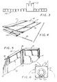
- Figure 3 is an elevational view of a cross section of a corrugated panel constituting the fixture, with two flutes removed for hinging purposes.
- Figure 4 is a partial perspective view of the corrugated panel, the oval channel and the form retaining shaft, shown in the disassembled form.
- Figure 5 is partial perspective view of the corrugated panel with the subpanels in angular position, and the oval channel and the form retaining shaft as attached to the subpanels.
- Figure 6 is a side elevational view of the lighting system in the folded configuration.
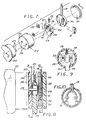
- Figure 7 is an exploded view of a disassembled locking lamp holder used to firmly hold a fluorescent tube as well as provide electrical power.
- Figure 8 is a sectional view of the locking lamp holder, taken along line 8-8 of Figure 7.
- Figure 9 is a sectional view of the locking lamp holder, taken along line 9-9 of Figure 8.
- Figure 10 is a sectional view of the locking lamp holder, taken along line 10-10 of Figure 8.
- Figure 11 is a rear perspective view of the lighting system showing the mounting device as attached to the rear of the lighting panel.
- Figure 12 is a top elevational view of the holding plate showing the ball and socket swivel device and the "Nylatch” fasteners.
- Figure 13 is a sectional view of the holding plate showing the ball and socket swiveling device, taken along line 13-13 of Figure 12.
- Figure 14 is a sectional view of the "Nylatch” expandable fasteners, taken along line 14-14 of Figure 12.
- Figure 1 is a perspective view of the present invention.
- the invention comprises an elongate corrugated plastic panel 24, wherein said panel is made into five subpanels by removing two flutes 17 of the corrugation out to provide for hinging.
- the panel 24 includes center panel 12 at the center of said panel, a pair of inner subpanels 11 and 13 each on one side of center subpanel 12, outer subpanel 10 positioned on the outer side of inner subpanel 11, and outer subpanel 14 positioned on outer side of inner subpanel 13. All subpanels 10, 11, 13 and 14 are symmetrically positioned and longitudinally extending in parallel to center subpanel 12. Removal of two flutes 17 at each juncture of said subpanels provided for convenient and flexible hinging of subpanels without adding extra weight.
- each subpanel In order to prevent the subpanels to revert back to their original positions after being flexed to a desired configuration, at each end of each subpanel a channel 15 in the shape of an oval is attached therein so that a deformable and form retaining shaft 16 having a substantially circular cross section may be easily inserted. Since shaft 16 is deformable, each subpanel can be manually positioned and held by the shaft in said position. Oval channel 15 allows for easy removal and replacement of shaft 16 such that in cases of metal fatigue, resulting in the shaft breakage, a new shaft can be inserted without having to replace the complete hinging mechanism or the lighting system itself.
- center subpanel 12 is always twice the width of the outer subpanels 10 and 14.
- the fluorescent lighting source 22 is placed on the center subpanel 12.
- Inner subpanels 11 and 13 and outer subpanels 10 and 14 are used to control the direction of and limit the output of the fluorescent lighting source 22.
- center subpanel 12 and inner subpanels 11 and 13 act as a reflective surface.
- a premolded aluminum reflective panel 21 could also optionally be added to act as a reflector panel.
- the lamp bracket 25, which is attached to the center subpanel 15, comprises a base and arcuate arm members made of resilient material to firmly hold each end of a fluorescent light in place.
- the pins 23 of the fluorescent light 22 are inserted into the spring loaded locking lamp holder 20, wherein the locking lamp holder 20 holds firmly onto the pins 22 and conducts electrical power to fluorescent light 22. Thereafter, the locking lamp holder 20 is inserted into the lamp bracket 25 which firmly holds the fluorescent light 22 in place.
- the corrugated panel 24 is shown with two flutes 17 of corrugation removed for dividing the panel 24 into five subpanels as well as providing a hinge means for the subpanels.
- the oval channels 15 are attached to the end of each subpanel providing for the form retaining and deformable shaft 16 to be easily inserted and removed for replacement purposes, wherein the deformable shaft 16 flexibly allows for the manual positioning of the subpanels in a desired position and prevents them from reverting back to a different configuration.
- a spring loaded locking lamp holder 20 firmly holds onto the pins 23 of the fluorescent light 22 and conducts electrical power to said fluorescent light.
- the spring loaded locking lamp holder 20 is described in more detail below.
- the spring loaded locker lamp holder 20 comprises a cylindrical enclosure 27 made of plastic material which on the flat surface 36 has two round holes 26 corresponding to the size of the pins 23 of a fluorescent lamp 22; a pin holder 34 which is inserted in the enclosure 27 having a flat top and bottom and round edges so that it could move back and forth within the confines of the enclosure 27; the side 37 of the pin holder 34 is also flat with a protrusion 38 for placing a spring 33 between the pin holder side 37 and the round surface 39 of the enclosure as shown in Figures 8 and 9; the opposite side of the pin holder 29 is extended in the shape of a square or rectangular which protrudes from a slot 40 on the round surface of the enclosure 27.
- Pin holder 34 contains two rectangular holes 41, wherein pin holding elements 28 are inserted.
- Pin holding element 28 is a piece of conductive metal with a flat top and a V shape bottom.
- On the flat top of the pin holder element 28 is a slot, wherein at one end there is a large circle, corresponding to the size of the holes 26 on the enclosure box 27, which gradually decreases to a smaller circle at the other end; a circular switching element 30 is thereafter inserted into the enclosure 27.
- Switching element 30 has two electrical elements 31 which are connected to the electrical power cord 18; and cap 32 is inserted to completely cover the enclosure box 27.
- the fluorescent light pins 23 are each inserted through the round holes 26 and at the same time by pressing the extended side 29 of the pin holder 34 allowing the large circles of the pin holding elements 28 to correspond to holes 26, thereby letting the pins 23 pass through and press down the V shape bottom of the pin holding element 28 and make contact with the electrical elements 31. After releasing the extended side 29 of the pin holder 34, the spring 33 will push the pin holder 34 back to its original place, providing for the small circles of the pin holding elements 28 to enclose the circumference of the pins 23 and to hold them firmly in place.
- the electrical power cord 18 is connected to a remote ballast located outside the lighting system.
- FIG 11 is a rear perspective view of the lighting system showing the mounting device used to mount or hold the lighting system in place.
- the mounting device comprises holding plate 42 which has a triangular plate 49 including socket 45 wherein a ball 44 is rotatably coupled with the socket 45.
- the ball 44 is welded into a stand rod 19 which in return is removably connected to a conventional motion picture stand 48 (not shown in full) called a "Century Stand" designed to hold flags and cutters.
- a screw knob 47 on the triangular plate 49 is loose, the ball 44 can freely be swiveled about in the socket 45. Once the desired position of the ball 44 has been decided, the screw knob 47 is tightened to keep the ball 44 and the rod stand 19 firmly in place.
- the holder plate 42 is a modified "foam core holder plate” manufactured by American Studio Equipment of Sun Valley, California, part number ME96.
- the holder plate 42 is modified to accept a pair of "Nylatch expandable fasteners” 46, model numbers HN5P-53-1 and HN5G-53-1.
- the holding plate 42 is removably attached via the Nylatch fasteners 46 to the mating plate 43 which is made of aluminium and is riveted to the rear of the center subpanel 12 using rivets 48, only one of which is shown.
- a safety loop 50 is permanently attached to the mating plate with the rivet, into which a safety cable may be inserted to prevent the fixture from falling in the event any of the future supporting elements fail for any reason.
- Figure 12 is a top elevational view of the holding plate 42 showing the triangular plate 49 and the socket 45 wherein the ball 44 is rotatably coupled with the socket 45 and may be rotated freely within the socket 45 as described above.
- Figure 13 is a sectional view of the holding plate 42 taken along the line 13-13 of Figure 12 as the holding plate 42 is attached to the mating plate 43. Tightening the screw knob 47 forces the triangular plate 49 to push against the ball 44 so as to keep the ball 44 firmly in the desired position.
Landscapes
- Engineering & Computer Science (AREA)
- General Engineering & Computer Science (AREA)
- Fastening Of Light Sources Or Lamp Holders (AREA)
Priority Applications (1)
| Application Number | Priority Date | Filing Date | Title |
|---|---|---|---|
| DE1992613220 DE69213220T2 (de) | 1992-06-02 | 1992-06-02 | Tragbare Beleuchtungsvorrichtung mit Leuchtstofflampe |
Applications Claiming Priority (1)
| Application Number | Priority Date | Filing Date | Title |
|---|---|---|---|
| US07/621,213 US5132885A (en) | 1990-11-29 | 1990-11-29 | Portable fluorescent lighting system |
Publications (2)
| Publication Number | Publication Date |
|---|---|
| EP0572733A1 true EP0572733A1 (de) | 1993-12-08 |
| EP0572733B1 EP0572733B1 (de) | 1996-08-28 |
Family
ID=24489222
Family Applications (1)
| Application Number | Title | Priority Date | Filing Date |
|---|---|---|---|
| EP92305067A Expired - Lifetime EP0572733B1 (de) | 1990-11-29 | 1992-06-02 | Tragbare Beleuchtungsvorrichtung mit Leuchtstofflampe |
Country Status (2)
| Country | Link |
|---|---|
| US (1) | US5132885A (de) |
| EP (1) | EP0572733B1 (de) |
Families Citing this family (35)
| Publication number | Priority date | Publication date | Assignee | Title |
|---|---|---|---|---|
| US5613761A (en) * | 1994-09-21 | 1997-03-25 | Raby, Sr.; Frederick R. | Material and method for fabricating a light fixture reflector, and, reflector produced thereby |
| US5918970A (en) * | 1996-01-24 | 1999-07-06 | Holophane Corporation | Outdoor luminaire assembly |
| US6632100B1 (en) | 1997-04-23 | 2003-10-14 | Anthony, Inc. | Lighting system method and apparatus socket assembly lamp insulator assembly and components thereof |
| US6638088B1 (en) | 1997-04-23 | 2003-10-28 | Anthony, Inc. | Lighting circuit, lighting system method and apparatus, socket assembly, lamp insulator assembly and components thereof |
| US6164801A (en) * | 1999-07-02 | 2000-12-26 | Teletec De Mexico, Sa, De Cv. | Portable lighting system |
| US6860617B2 (en) * | 1999-10-01 | 2005-03-01 | Ole K. Nilssen | Compact luminaire |
| US6439736B1 (en) * | 1999-10-01 | 2002-08-27 | Ole K. Nilssen | Flattenable luminaire |
| US6435693B1 (en) * | 1999-10-01 | 2002-08-20 | Ole K. Nilssen | Lighting assemblies for mounting in suspended ceiling configured to permit more compact shipment and storage |
| US6318884B1 (en) | 2000-04-21 | 2001-11-20 | Patricia Electric, Inc. | Work light assembly using compact fluorescent lamps |
| AU2001270053A1 (en) * | 2000-06-26 | 2002-01-08 | Anthony, Inc. | Lighting circuit, lighting system method and apparatus, socket assembly, lamp insulator assembly and components thereof |
| US6573328B2 (en) * | 2001-01-03 | 2003-06-03 | Loctite Corporation | Low temperature, fast curing silicone compositions |
| US6561683B1 (en) | 2001-07-12 | 2003-05-13 | Alex Jachno | Portable lighting device |
| US20050161883A1 (en) * | 2004-01-27 | 2005-07-28 | World Poker Tour, Llc | Constant pace card game |
| US20050225975A1 (en) * | 2004-04-07 | 2005-10-13 | Koji Takamura | Area lighting device |
| US20060050506A1 (en) * | 2004-09-03 | 2006-03-09 | Ngai Peter Y | Light diffuser element with brightness distribution control |
| USD544994S1 (en) * | 2004-11-10 | 2007-06-19 | Ip Holdings, Llc | Light reflector |
| USD558915S1 (en) * | 2006-08-08 | 2008-01-01 | Matsushita Electric Industrial Co., Ltd. | Holder for fluorescent lamp |
| US20090135597A1 (en) * | 2007-11-27 | 2009-05-28 | Kay Gregory L | Linear lamp |
| USD603086S1 (en) | 2009-04-21 | 2009-10-27 | Light Sources, Inc. | T12 step base |
| US8109647B2 (en) * | 2009-07-28 | 2012-02-07 | Lg Innotek Co., Ltd. | Lighting device |
| US8568002B2 (en) * | 2010-03-05 | 2013-10-29 | Southpac Trust International Inc., Trustee of the LDH Trust | Light diffusion and condensing fixture |
| US8192045B2 (en) * | 2010-05-20 | 2012-06-05 | Kino Flo, Inc. | Portable fluorescent lighting system with long-life hinge mechanism |
| USD672902S1 (en) * | 2011-10-25 | 2012-12-18 | Abl Ip Holding Llc | Light fixture |
| USD672909S1 (en) | 2011-10-25 | 2012-12-18 | Abl Ip Holding Llc | Light fixture |
| USD730568S1 (en) * | 2012-03-27 | 2015-05-26 | Lunera Lighting, Inc. | Lighting fixture |
| GB2495355B (en) * | 2012-07-02 | 2013-08-28 | Gew Ec Ltd | Ink curing apparatus |
| US9945542B2 (en) * | 2012-11-02 | 2018-04-17 | The Wand Lite Company Limited | Lighting device |
| USD768910S1 (en) | 2015-04-15 | 2016-10-11 | Ip Holdings, Llc | Light reflector |
| USD770081S1 (en) | 2015-09-01 | 2016-10-25 | Ip Holdings, Llc | Horticulture grow light |
| US10309592B2 (en) | 2016-08-10 | 2019-06-04 | Bestop Baja, Llc | Rear facing multi-light and function light bar |
| USD848662S1 (en) | 2017-11-03 | 2019-05-14 | Hgci, Inc. | Light reflector |
| US20200022313A1 (en) | 2018-07-19 | 2020-01-23 | Just Greens Llc | Fixtureless Lamp |
| US11273751B2 (en) | 2019-10-08 | 2022-03-15 | Bestop Baja, Llc | Auxiliary light for mounting to a vehicle |
| US11067254B1 (en) | 2019-10-08 | 2021-07-20 | Bestop Baja, Llc | Auxiliary light for mounting to a vehicle |
| CN212617816U (zh) * | 2020-06-06 | 2021-02-26 | 亮兮柯电气(嘉兴)有限公司 | 一种投光灯转向结构 |
Citations (6)
| Publication number | Priority date | Publication date | Assignee | Title |
|---|---|---|---|---|
| CH137327A (de) * | 1929-01-15 | 1929-12-31 | Meier Emil | Zusammenlegbarer Reflektor mit Halter. |
| CH169489A (de) * | 1933-06-03 | 1934-05-31 | Tschirnich Alois | Beleuchtungskörper mit Reflektor für Spinnmaschinen. |
| DE1657287A1 (de) * | 1967-05-30 | 1972-04-13 | Walter Dr Kanne | Mundpflegegerät |
| US4646201A (en) * | 1984-12-14 | 1987-02-24 | Lerner David R | Fluorescent light mounting system |
| US4669033A (en) * | 1985-09-19 | 1987-05-26 | Specuflex, Inc. | Adjustable optical reflector for fluorescent fixture |
| US4782428A (en) * | 1987-08-21 | 1988-11-01 | Ross Lowell | Collapsible fluorescent light for photography |
Family Cites Families (3)
| Publication number | Priority date | Publication date | Assignee | Title |
|---|---|---|---|---|
| FR1280818A (fr) * | 1960-12-10 | 1962-01-08 | Montage de source d'énergie rayonnante | |
| US3852582A (en) * | 1973-06-20 | 1974-12-03 | R Lowell | Lighting arrangement for photographic work |
| US4814958A (en) * | 1988-01-22 | 1989-03-21 | Hsieh Chen Huang | Straight type fluorescent lamp device with light reflecting plates |
-
1990
- 1990-11-29 US US07/621,213 patent/US5132885A/en not_active Expired - Lifetime
-
1992
- 1992-06-02 EP EP92305067A patent/EP0572733B1/de not_active Expired - Lifetime
Patent Citations (6)
| Publication number | Priority date | Publication date | Assignee | Title |
|---|---|---|---|---|
| CH137327A (de) * | 1929-01-15 | 1929-12-31 | Meier Emil | Zusammenlegbarer Reflektor mit Halter. |
| CH169489A (de) * | 1933-06-03 | 1934-05-31 | Tschirnich Alois | Beleuchtungskörper mit Reflektor für Spinnmaschinen. |
| DE1657287A1 (de) * | 1967-05-30 | 1972-04-13 | Walter Dr Kanne | Mundpflegegerät |
| US4646201A (en) * | 1984-12-14 | 1987-02-24 | Lerner David R | Fluorescent light mounting system |
| US4669033A (en) * | 1985-09-19 | 1987-05-26 | Specuflex, Inc. | Adjustable optical reflector for fluorescent fixture |
| US4782428A (en) * | 1987-08-21 | 1988-11-01 | Ross Lowell | Collapsible fluorescent light for photography |
Also Published As
| Publication number | Publication date |
|---|---|
| US5132885A (en) | 1992-07-21 |
| EP0572733B1 (de) | 1996-08-28 |
Similar Documents
| Publication | Publication Date | Title |
|---|---|---|
| EP0572733B1 (de) | Tragbare Beleuchtungsvorrichtung mit Leuchtstofflampe | |
| US5890793A (en) | Portable luminescent lighting system | |
| US6176598B1 (en) | Light fixture flexible reflector | |
| US20190178479A1 (en) | Set Light Fixture and Application of Same | |
| US3852582A (en) | Lighting arrangement for photographic work | |
| US20110222274A1 (en) | Hands-Free Multi-Positional Task Light and Method of Use Thereof | |
| US4819353A (en) | Illuminated picture frame | |
| US10429013B1 (en) | Portable worklight | |
| CA2605732C (en) | An adjustable track lighting system adapted to support multiple types of light sources | |
| US5303127A (en) | Lighting fixture | |
| US6554459B2 (en) | Support bracket for light stand | |
| US20080186699A1 (en) | Task Light System | |
| US5915828A (en) | Motion picture lighting fixture | |
| US7434966B2 (en) | Soft projected lighting device using multiple par lamps | |
| US6719434B1 (en) | Foldable light diffusion box with frame assembly | |
| US6109757A (en) | Case light assembly system | |
| EP1759146B1 (de) | Leuchte mit flexiblem reflektor und durchsichtigem träger | |
| US4638413A (en) | Combination spotlight and table lamp | |
| US4811183A (en) | Tamper-resistant fluorescent tube assembly holder/adapter for lamps | |
| CA3086521C (en) | Lighting devices and methods | |
| US4984135A (en) | Interchangeable camera light mount | |
| CN210979742U (zh) | 一种视觉艺术设计用灯光架 | |
| US6561683B1 (en) | Portable lighting device | |
| CN219199069U (zh) | 一种安装支架和照明设备 | |
| CA2343470C (en) | Foldable modular light diffusion box |
Legal Events
| Date | Code | Title | Description |
|---|---|---|---|
| PUAI | Public reference made under article 153(3) epc to a published international application that has entered the european phase |
Free format text: ORIGINAL CODE: 0009012 |
|
| 17P | Request for examination filed |
Effective date: 19930607 |
|
| AK | Designated contracting states |
Kind code of ref document: A1 Designated state(s): DE FR GB IT |
|
| 17Q | First examination report despatched |
Effective date: 19941125 |
|
| GRAG | Despatch of communication of intention to grant |
Free format text: ORIGINAL CODE: EPIDOS AGRA |
|
| GRAH | Despatch of communication of intention to grant a patent |
Free format text: ORIGINAL CODE: EPIDOS IGRA |
|
| GRAH | Despatch of communication of intention to grant a patent |
Free format text: ORIGINAL CODE: EPIDOS IGRA |
|
| GRAA | (expected) grant |
Free format text: ORIGINAL CODE: 0009210 |
|
| AK | Designated contracting states |
Kind code of ref document: B1 Designated state(s): DE FR GB IT |
|
| ITF | It: translation for a ep patent filed | ||
| REF | Corresponds to: |
Ref document number: 69213220 Country of ref document: DE Date of ref document: 19961002 |
|
| ET | Fr: translation filed | ||
| PLBQ | Unpublished change to opponent data |
Free format text: ORIGINAL CODE: EPIDOS OPPO |
|
| PLBI | Opposition filed |
Free format text: ORIGINAL CODE: 0009260 |
|
| PLBF | Reply of patent proprietor to notice(s) of opposition |
Free format text: ORIGINAL CODE: EPIDOS OBSO |
|
| 26 | Opposition filed |
Opponent name: FGV SCHMIDLE GMBH UND KOBOLD LICHT EINKAUFS- UND O Effective date: 19970527 |
|
| PLBF | Reply of patent proprietor to notice(s) of opposition |
Free format text: ORIGINAL CODE: EPIDOS OBSO |
|
| PLBF | Reply of patent proprietor to notice(s) of opposition |
Free format text: ORIGINAL CODE: EPIDOS OBSO |
|
| PLBL | Opposition procedure terminated |
Free format text: ORIGINAL CODE: EPIDOS OPPC |
|
| PLBM | Termination of opposition procedure: date of legal effect published |
Free format text: ORIGINAL CODE: 0009276 |
|
| STAA | Information on the status of an ep patent application or granted ep patent |
Free format text: STATUS: OPPOSITION PROCEDURE CLOSED |
|
| 27C | Opposition proceedings terminated |
Effective date: 19990502 |
|
| REG | Reference to a national code |
Ref country code: GB Ref legal event code: IF02 |
|
| PLAB | Opposition data, opponent's data or that of the opponent's representative modified |
Free format text: ORIGINAL CODE: 0009299OPPO |
|
| PGFP | Annual fee paid to national office [announced via postgrant information from national office to epo] |
Ref country code: FR Payment date: 20110629 Year of fee payment: 20 |
|
| PGFP | Annual fee paid to national office [announced via postgrant information from national office to epo] |
Ref country code: GB Payment date: 20110628 Year of fee payment: 20 |
|
| PGFP | Annual fee paid to national office [announced via postgrant information from national office to epo] |
Ref country code: IT Payment date: 20110627 Year of fee payment: 20 |
|
| PGFP | Annual fee paid to national office [announced via postgrant information from national office to epo] |
Ref country code: DE Payment date: 20110629 Year of fee payment: 20 |
|
| REG | Reference to a national code |
Ref country code: DE Ref legal event code: R071 Ref document number: 69213220 Country of ref document: DE |
|
| REG | Reference to a national code |
Ref country code: DE Ref legal event code: R071 Ref document number: 69213220 Country of ref document: DE |
|
| REG | Reference to a national code |
Ref country code: GB Ref legal event code: PE20 Expiry date: 20120601 |
|
| PG25 | Lapsed in a contracting state [announced via postgrant information from national office to epo] |
Ref country code: DE Free format text: LAPSE BECAUSE OF EXPIRATION OF PROTECTION Effective date: 20120605 |
|
| PG25 | Lapsed in a contracting state [announced via postgrant information from national office to epo] |
Ref country code: GB Free format text: LAPSE BECAUSE OF EXPIRATION OF PROTECTION Effective date: 20120601 |