EP0572747A1 - Arroseur rotatif à arc d'aspersion réglable - Google Patents
Arroseur rotatif à arc d'aspersion réglable Download PDFInfo
- Publication number
- EP0572747A1 EP0572747A1 EP92630058A EP92630058A EP0572747A1 EP 0572747 A1 EP0572747 A1 EP 0572747A1 EP 92630058 A EP92630058 A EP 92630058A EP 92630058 A EP92630058 A EP 92630058A EP 0572747 A1 EP0572747 A1 EP 0572747A1
- Authority
- EP
- European Patent Office
- Prior art keywords
- arc
- arcuate
- cylindrical
- coverage
- sprinkler
- Prior art date
- Legal status (The legal status is an assumption and is not a legal conclusion. Google has not performed a legal analysis and makes no representation as to the accuracy of the status listed.)
- Ceased
Links
Images


Classifications
-
- B—PERFORMING OPERATIONS; TRANSPORTING
- B05—SPRAYING OR ATOMISING IN GENERAL; APPLYING FLUENT MATERIALS TO SURFACES, IN GENERAL
- B05B—SPRAYING APPARATUS; ATOMISING APPARATUS; NOZZLES
- B05B1/00—Nozzles, spray heads or other outlets, with or without auxiliary devices such as valves, heating means
- B05B1/26—Nozzles, spray heads or other outlets, with or without auxiliary devices such as valves, heating means with means for mechanically breaking-up or deflecting the jet after discharge, e.g. with fixed deflectors; Breaking-up the discharged liquid or other fluent material by impinging jets
- B05B1/262—Nozzles, spray heads or other outlets, with or without auxiliary devices such as valves, heating means with means for mechanically breaking-up or deflecting the jet after discharge, e.g. with fixed deflectors; Breaking-up the discharged liquid or other fluent material by impinging jets with fixed deflectors
-
- B—PERFORMING OPERATIONS; TRANSPORTING
- B05—SPRAYING OR ATOMISING IN GENERAL; APPLYING FLUENT MATERIALS TO SURFACES, IN GENERAL
- B05B—SPRAYING APPARATUS; ATOMISING APPARATUS; NOZZLES
- B05B3/00—Spraying or sprinkling apparatus with moving outlet elements or moving deflecting elements
- B05B3/02—Spraying or sprinkling apparatus with moving outlet elements or moving deflecting elements with rotating elements
- B05B3/04—Spraying or sprinkling apparatus with moving outlet elements or moving deflecting elements with rotating elements driven by the liquid or other fluent material discharged, e.g. the liquid actuating a motor before passing to the outlet
- B05B3/0417—Spraying or sprinkling apparatus with moving outlet elements or moving deflecting elements with rotating elements driven by the liquid or other fluent material discharged, e.g. the liquid actuating a motor before passing to the outlet comprising a liquid driven rotor, e.g. a turbine
-
- B—PERFORMING OPERATIONS; TRANSPORTING
- B05—SPRAYING OR ATOMISING IN GENERAL; APPLYING FLUENT MATERIALS TO SURFACES, IN GENERAL
- B05B—SPRAYING APPARATUS; ATOMISING APPARATUS; NOZZLES
- B05B15/00—Details of spraying plant or spraying apparatus not otherwise provided for; Accessories
- B05B15/70—Arrangements for moving spray heads automatically to or from the working position
- B05B15/72—Arrangements for moving spray heads automatically to or from the working position using hydraulic or pneumatic means
- B05B15/74—Arrangements for moving spray heads automatically to or from the working position using hydraulic or pneumatic means driven by the discharged fluid
-
- Y—GENERAL TAGGING OF NEW TECHNOLOGICAL DEVELOPMENTS; GENERAL TAGGING OF CROSS-SECTIONAL TECHNOLOGIES SPANNING OVER SEVERAL SECTIONS OF THE IPC; TECHNICAL SUBJECTS COVERED BY FORMER USPC CROSS-REFERENCE ART COLLECTIONS [XRACs] AND DIGESTS
- Y10—TECHNICAL SUBJECTS COVERED BY FORMER USPC
- Y10S—TECHNICAL SUBJECTS COVERED BY FORMER USPC CROSS-REFERENCE ART COLLECTIONS [XRACs] AND DIGESTS
- Y10S239/00—Fluid sprinkling, spraying, and diffusing
- Y10S239/01—Pattern sprinkler
Definitions
- This invention relates to adjustable arc of coverage nozzles to provide uniform water precipitation over each area of coverage selected and to provide special patterns of precipitation.
- Patent No. 4,867,378, issued September 19, 1989, discloses a sprinkler having an adjustable arc of oscillation rotating nozzle with the arc of oscillation being setable and indicated on the top of the nozzle.
- the market advantage for a sprinkler that can be easily set to cover a particular area from the top was discussed.
- the sprinkler of the referenced patent application was for large area coverage, long throw radius, oscillating nozzle sprinklers.
- This application discloses a concept for providing an adjustable and indicated arc of coverage for smaller and intermediate areas of coverage sprinklers which can be fixed spray or have a rotating distributing head providing a plurality of streams for intermediate ranges with an adjustable arc of coverage and automatically provide for the same precipitation rate, i.e., one inch per square foot per hour, for the area covered by the selected arc.
- the arc of coverage can easily be set and indicated on the top of the nozzle. Ease of setting a sprinkler for the required arc of coverage and having it provide a matched precipitation for its area of coverage to those sprinklers installed and set in other areas of the yard would greatly reduce the required inventory and time required for installation as well as provide more uniform coverage than now being achieved in present day installations.
- Another feature of this invention not previously provided for in an adjustable arc of coverage sprinkler nozzle is the ease of cleaning. Being able to easily clean dirt from the arcuate slot used to control flow for the desired arc of sprinkler coverage is an important feature and greatly enhances the usability in systems with well pumped water and effluent water supplied systems.
- the adjustable arcuate opening is upstream with pressure trying to close it, thus making it a much simpler design to manufacture and also to clean by just pushing down on the center arcuate valving member against the pressure or small spring force to allow dirt particles to pass through.
- a configuration is shown where the single piece arcuate valving control member may be easily removed and replaced from the top, which can also be used to easily provide some special patterns such as a strip spray (long rectangular pattern). Having the arcuate valving member removable from the top of the head with as few parts as possible also greatly enhances the ease of manufacture and service.
- the nozzle exit may be molded into the end of a riser tube for a pop-up sprinkler without regard to having to assemble or service small cavities or holes from the underside.
- the disclosed configuration ensures getting the sprinkler reassembled with the proper flow area to provide for a matched sprinkler precipitation rate.
- flow slot height (thickness) is manufactured into the parts giving them a known precipitation rate for particular parts regardless of wha+ arc is set.
- Still another feature of having the arc setting arcuate valving action take place below the exit of the nozzle is the ability to apply the adjustable arc of coverage feature to a stream rotary sprinkler of the type described in my Patent No. 4,353,507 and in Patents Nos. 4,842,201; 4,815,662; and 4,867,379.
- a setable arc of coverage configuration for a rotating distributing nozzle is shown.
- the benefits of this invention eliminate the need to inventory the many separate arc slots or flow selection discs that other sprinklers of this type require.
- the precipitation rate of water per unit area of coverage is fixed by the slot thickness, i.e., inches of precipitation per square foot per hour.
- the slot thickness remains constant for the increased arc and the sprinkler's total flow rate is increased proportionally to the increased arc of coverage.
- the flow slot be set to give a known precipitation rate so that as the sprinklers are used in various parts of a lawn, that all areas receive water coverage equally, i.e., one inch per square foot per hour, regardless of the arc that is set or a random adjustment that someone may make.
- the manufactured fixed slot thickness created between the center shaft and the nozzle housing hole fixes the precipitation rate regardless of what arc is set for the improved adjustable arc of coverage nozzles of this invention. Upstream throttling to control the sprinkler range and patterns is provided for but the discharge design slot thickness is maintained at the final discharge for all of the selected arcs and configurations.
- a configuration is shown that provides for adjusting the range of coverage while retaining the distribution rate slot thickness.
- the range of coverage can be adjusted to compensate for system pressure differences at each head that has this added feature or throttle the pressure to the sprinkler's stream slot which will reduce the range of coverage and overall flow rate of the sprinkler.
- Other configurations are shown that selectively provide upstream discharge slot throttling around the selected arcuate slot for special sprinkler pattern effects.
- Another object is to provide a nozzle that can be easily cleaned.
- Still another object is to provide a configuration where special pattern sprinklers can be provided by changing only a single part in a standard inventory housing.
- a further object is to provide a simple two-part adjustable arc sprinkler where the arc selection member can be removed from the top (outside) for cleaning.
- Another object of the invention is to provide an arc selection valving member setable from the outside of a rotating stream nozzle sprinkler for any desired arc of coverage.
- Another object of the invention is to provide an adjustable arc of coverage fixed spray nozzle where the arc of coverage is setable and indicated on the top of the sprinkler.
- Still a further object of the invention is to provide for various flow increases or decreases around the adjustable arcuate opening to produce particular patterns of different ranges as well as for the desired arc of coverage.
- Another object is to provide an adjustable arc of coverage spray nozzle with an upstream of the nozzle pressure throttling means for spray pattern range control.
- a basic spray nozzle assembly 1 with adjustable arc of coverage is shown in Figure 1. It has only three (3) parts to provide a spray that provides a matched precipitation pattern for all the spray heads used in a system regardless of what arc of coverage they are set for. The three parts are:
- the cylindrical, or annular, housing 3 is defined by an outer circular wall 5 and an inner wall 7.
- Inner wall 7 has an upper upwardly diverging surface 7A and a lower cylindrical surface 7B.
- the upper diverging surface 7A has a narrow rib 13 protruding upwardly for mounting and spacing a flow spray deflector member 15.
- Spray deflector member 15 is formed having an annular body 16 with a center cylindrical opening, or hole, 17.
- Annular body 16 has an annular top surface 18 with a small peripheral edge 20.
- the annular top surface 18 has a diameter substantially equal to the outer circular wall 5.
- An upwardly diverging deflecting surface 22 has its upper end connected to peripheral edge 20 and is positioned in the upwardly diverging surface 7A of housing 3 and extends to a point radially inwardly of cylindrical surface 7B.
- the inner surface of the cylindrical hole 17 is formed to meet the deflecting surface 22 at a circular edge A.
- a recess 14 is formed in the upwardly diverging deflecting surface 22 to receive the rib 13.
- the rib 13 provides (1) the supporting means for the spray deflector member 15; and (2) the spacing means for properly spacing the upwardly diverging surface 7A and the upwardly diverging deflecting surface 22.
- the rib 13 is fixed in the recess 14 by being glued or sonic-welded.
- Arc set selection member 21 comprises a cylindrical member 24 with an enlarged lower end 26.
- Said enlarged lower end 26 appears as a sleeve-like member fixed to the cylindrical member 24 with a diameter larger than cylindrical member 24, and being coaxial therewith.
- Said sleeve-like member has an upwardly facing spiral surface 28 extending substantially 360° around the cylindrical member 24, and a downwardly facing lower surface at the bottom of cylindrical member 24 for a greater part of its circumference forming a radial extension thereof.
- the remaining part 25 of the circumference is open along with material removed at 27 to provide an enlarged inlet upwardly to a point just below the top edge of surface 28 and the front of the bottom edge of surface 28 where it enters the space between cylindrical member 24 and cylindrical surface 7B.
- Enlarged lower end 26 has a diameter sized to have a rotatable and slidable fit in the inner cylindrical surface 7B of housing 3, and cylindrical member 24 has a diameter sized to have a rotatable and slidable fit in the inner cylindrical surface of hole 17.
- a narrow axial closure rib 36 is formed on the surface of cylindrical member 24 extending upwardly from the upper end of spiral surface 28 to permit axial movement of the arc set selection member 21 as it selects the proper arc.
- Axial rib 36 has a slidable fit within cylindrical surface 7B.
- a narrow axial closure rib 38 is formed on wall 7 of housing 3 extending along the inner lower cylindrical surface 7B from the bottom thereof, to meet with the rib 13, both being of the same width, on diverging surface 7A.
- the inner surface of axial rib 38 has a slidable engagement with cylindrical member 24.
- the cylindrical member 24 has a groove 40 in the top thereof for receiving the end of a screwdriver, for example, for turning it to move axial closure rib 36 with respect to axial closure rib 38.
- an adjustable arcuate discharge slot 50 is formed between the movable axial closure rib 36, axial closure rib 38, cylindrical surface 7B, and cylindrical member 24.
- spiral surface 28 biased against the lower end of axial rib 38 such as by water pressure, it can be seen that as the arc set selection member 21 is rotated clockwise to increase the adjustable arcuate discharge slot 50, the spiral surface 28 is cammed downwardly rotating the movable axial rib 36 away from the axial rib 38.
- the enlarged inlet provided by remaining part 25 and material removed at 27 is further enlarged by the admission of water flow over the spiral surface 28 to provide a greater supply as the adjustable arcuate discharge slot 50 enlarges.
- This movement of the lower end of arc set selection member 21 below the bottom 42 of the cylindrical housing 3 continues as long as the axial closure rib 36 has spacing to engage the bottom of axial closure rib 38.
- the adjustable arcuate discharge slot 50 is fully open the arcuate discharge slot 50 is substantially a full circle, with the water flow from a riser or inlet pipe being directed directly into the fully open arcuate discharge slot 50.
- Spray deflector member 15 has an arrowhead 19 on top surface 18 representing the location of axial closure rib 38, and arc set selection member 21 has an arrowhead 23 on its top surface representing the location of axial closure rib 36. Angular positioning of the spray nozzle is clearly indicated by indicia on the surface 18, such as 90°, 180° and 270°.
- Three downwardly extending alignment and retention ribs 52 extend from the bottom 42 of cylindrical housing 3 around cylindrical surface 7B. It can be seen that the inner surface of these ribs 52 guide the enlarged lower end 26 of the arc set selection member 21 as it extends below its bottom. Further, inwardly projecting retention bumps, or projections, 54 prevent the arc set selection member 21 from dropping out of the cylindrical housing 3.
- a modified spray nozzle assembly 1A is shown in Figure 4. It has four (4) parts; the parts are:
- the cylindrical, or annular, housing 3A is formed as housing 3 of Figure 1 with the following exceptions:
- the spray deflector member 15 is formed as it is in Figure 1.
- the arc set selection member 21A is formed as arc set selection member 21 of Figure 1 with the following exceptions:
- a narrow axial rib 36 is formed on the surface of cylindrical member 24 extending upwardly from the upper end of spiral surface 28A in line with the axial stepped surface 29 to permit axial movement of the arc set selection member 21A as it selects the proper arc.
- Axial rib 36 has a slidable fit within cylindrical surface 7B but does not extend to the outer surface of the enlarged lower end 26A.
- the slot closure rib 36 has a flow surface which is slightly deflected at the top at 37 to turn the slot flow along the rib 36 slightly inwardly towards the open arcuate slot area as necessary to form the desired spray edge exiting from the spray deflector 15 to provide the proper angular discharge.
- a narrow axial rib 38 is formed on wall 7 of housing 3A extending along the inner lower cylindrical surface 7B from the bottom thereof, to meet with the rib 13, both being of the same width, on diverging surface 7A.
- the inner surface of axial rib 38 has a slidable engagement with cylindrical member 24 such as axial rib 36 has with cylindrical surface 7B.
- the cylindrical member 24 has a groove 40 in the top thereof for receiving the end of a screwdriver, for example, for turning it to move axial rib 36 with respect to axial rib 38.
- an adjustable arcuate discharge slot 50A is formed between the movable axial rib 36, axial rib 38, cylindrical surface 7B, and cylindrical member 24.
- spiral surface 28A biased against the spiral surface 42A such as by water pressure, it can be seen that as the arc set selection member 21 is rotated clockwise to increase the adjustable arcuate discharge slot 50A, the spiral surface 28A is cammed downwardly rotating the movable axial rib 36 away from the axial rib 38.
- Arcuate discharge slot area 50A is supplied with flow through the opening created by the stepped spiral surfaces' interaction as defined in Figure 4 by the opening with sides 42A, 38, 28A and 29. This supply area is desired to be two to three times the area of the discharge arcuate slot 50.
- a modified spray nozzle assembly 1B shown in Figure 5 is integrally connected to the top of a riser 80.
- This nozzle assembly 1B comprises two parts:
- the cylindrical housing 3B includes an outer circular wall 5 and an inner wall 7.
- Inner wall 7 has an upper upwardly diverging surface 7A and a lower cylindrical surface 7B.
- Riser 80 supplies pressurized water to the nozzle assembly 1B.
- a narrow axial rib 38 is formed on wall 7 of housing 3B extending along the inner lower cylindrical surface 7B from the bottom thereof to the top of diverging surface 7A.
- the top of arc set selection member 21B is formed with an upwardly diverging deflecting surface 22.
- the diverging deflection surface 22 has a round top surface 18B with a small peripheral edge 20; a cylindrical member 24B extends downwardly from the bottom of the diverging surface 22.
- Cylindrical member 24B has an enlarged lower end 26B. Said enlarged lower end 26B appears as a sleeve-like member fixed to the cylindrical member 24B with a diameter larger than cylindrical member 24B, and being coaxial therewith.
- Said sleeve-like member has an upwardly facing spiral surface 28 extending substantially 360° around the cylindrical member 24B, and a downwardly facing lower surface at the bottom of cylindrical member 24B extending for a greater part of its circumference forming a radial extension thereof.
- Enlarged lower end 26B has a diameter sized to have a rotatable and slidable fit in the inner cylindrical surface 7B of housing 3B.
- a narrow axial rib 36 is formed on the surface of cylindrical member 24B extending upwardly from the upper end of spiral surface 28 in line with the axial stepped surface 29 to permit axial movement of the arc set selection member 21 as it relates to the proper arc.
- the round flat top surface 18B of arc set selection member 21B has a groove 40 for receiving the end of a screwdriver, for example, for turning it to move axial rib 36 with respect to axial rib 38. It can be seen that an adjustable arcuate discharge slot is formed between axial rib 36, axial rib 38, cylindrical surface 7B, and cylindrical member 24B. The operation is the same as in Figure 1.
- the smaller part of this circumference of the radial extension of cylindrical member 24B left open is an opening 41 axially throughthe low end of the spiral surface 28 adjacent stepped surface 29.
- a short projection 43 at the low end of the spiral surface 28 prevents the low end of the axial rib 38 from running into opening 41 and accidentally permitting the arc set selection member 21B to be disconnected.
- the arc set select ion member 21B is moved downwardly and rotated to intentionally align the axial rib 38 with the opening 41.
- a spring 45 is placed between the bottom of the arc set selection member 21B and a small circular plate 47 supported by three equally spaced ribs 49 connected to the riser 80.
- a support and guide pin 51 is connected to the center of the bottom of the arc set selection member 21B and extends through the coil spring 45 and through a hole 53 in the middle of small circular plate 47. This arrangement provides for proper alignment and movement of the arc set selection member 21B.
- the arc set relationship of the right and left sides of the spray pattern are shown by the arrowhead 79 and the rib 38 whose relationship can be seen from a view of the top of the spray nozzle.
- Slot end flow enhancement notches can be formed as a radial cut-out into cylinder wall 7B adjacent the fixed axial rib 38 and radially inward cut 41 into cylindrical surface of enlarged end 26B and shaft 24B at the movable axial rib 36.
- Figure 8 shows a modified sectional view looking down along line 8-8 of Figure 5 showing the adjustable arcuate discharge flow control slot of a modified arcuate valving means as modified to produce duplicate adjustable arcuate sprays 180° apart as is desired for strip spray sprinklers used to produce rectangular patterns.
- the adjustable arcuate valving area has been configured to provide for two fixed axial ribs 38A and 38B with two movable axial ribs 36A and 36B and matching spiral surfaces 28A and 28B extending approximately 180° around the lower end of arc set member 21B but whose function is the same as that described for spiral surface 28 and fixed axial rib 38 in Figure 5.
- Flow enhancement radial cut-outs at 78A and 75A and 78B and 75B enhance the amount of water at each side of each of the 180° apart spray patterns, giving these edges enhanced range and better defined rectangular corners.
- FIG. 9 An adjustable arc of coverage rotating distributing nozzle sprinkler 100 is shown in Figure 9. This sprinkler consists of five (5) main parts as follows:
- the riser 131 has an annular cover flange 132 adjacent the top thereof having a center hole 133.
- Arc set selection means 123 includes an arcuate slot outer cylinder 104 mounted for rotation in center hole 133.
- An inverted truncated conical member 103 positioned above the cover flange 132 has its smaller end fixed to arcuate slot outer cylinder 104 and has its larger end mounted on the top of riser 131 for rotation.
- a cylindrical member 102 is connected to the larger end so that it can turn the arcuate slot outer cylinder 104 when desired for arc selection.
- the arcuate slot outer cylinder 104 has a movable arcuate slot closure rib 105.
- the fixed center bearing post 109 extends upwardly from a rotary drive housing 130 in the riser 131, into the arcuate slot outer cylinder 104 to the top thereof.
- a fixed arcuate slot closure rib 107 extends axially along the fixed center bearing post 109.
- An adjustable arcuate slot opening 120 is formed between the arcuate slot closure ribs 105 and 107, the surface of bearing post 109, and the inner surface of outer cylinder 104.
- the adjustable arcuate slot opening 120 is adjustable from the out-side by cylindrical member 102.
- a sleeve-like member 106 having an upper spiral surface 112 and a flat lower surface is slidably placed over fixed center bearing post 109 with a slot at the location of the axially displaced ends of the spiral surface 112.
- the fixed rib 107 is placed in said slot.
- a coil spring 108 is placed around said fixed center bearing post 109 with one end against the flat lower surface of sleeve-like member 106 and the other end against the top of housing 130. This spring action biases the spiral surface 112 against arcuate slot closure rib 105 for movement into or out of the space between center bearing post 109 and outer cylinder 104.
- arcuate slot outer cylinder 104 When the arcuate slot outer cylinder 104 is rotated in a counter-clockwise direction by cylindrical member 102, movable arcuate slot closure rib 105 cams the sleeve-like member 106 downward against spring 108 to provide a desired larger arcuate slot opening 120 to feed water pressure to the setable arcuate discharge orifice slot as previously described for the Figure 1 spray nozzle.
- spring 108 biases sleeve-like member 106 upward to provide a desired smaller arcuate slot opening 120.
- Rotating distributing head 121 is fixed to a rotary drive shaft 150 extending from the upper end of bearing post 109.
- a drive mechanism is located in housing 130.
- the arcuate discharge orifice slot axial sheet of water strikes surface 122 and is turned radially outward.
- the stream channels 124 collect some of the axial discharge sheet into discrete streams of water that have more momentum and penetrate the air to a greater distance than the spray droplets exiting the sprinkler deflector off a smooth surface 122.
- Riser 131 has a water source connected to its lower end to provide the driving fluid for the rotating drive contained in housing 130 and then is supplied up through annular area 134 to the open area above the housing 130.
- An additional axial flow passage 170 is cut inwardly into the center drive shaft housing 130 and as top surface 112 is moved down below the top of passage 170, additional flow is provided.
- an additional flow opening 160 may be provided in the lower inner surface 110 of slot outer cylinder 104 that faces the side surface of sleeve-like member 106.
- sleeve-like member 106 When sleeve-like member 106 is moved downward, at one point the top surface of the opening 160 becomes open above the spiral surface 112, admitting additional flow between the fixed rib 107 and movable rib 105.
- the lower edge surface 110 of the slot outer cylinder 104 could have a matching spiral surface to that of the top surface 112 of the outer cylinder 104 to achieve the seal arrangement of Figure 4.
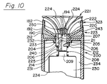
- FIG. 10 An adjustable arc of coverage rotating distributing nozzle sprinkler 200 is shown in Figure 10. This sprinkler consists of seven (7) main parts as follows:
- the riser 231 has an annular cover flange 232 adjacent the top thereof with a center hole 233.
- Arc set selection member 223 includes an arcuate slot outer cylinder 204 mounted for rotation in center hole 233.
- a flange extends from the bottom of cylinder 204 under the edge of flange 232 around the center hole 233.
- a flange-like member 190 is fixed adjacent to the top of the cylinder 204 and extends over the top of flange 232.
- Flange-like member 190 extends to the top of riser 231 and forms a rotatable upper cylindrical extension 192 of the riser 231.
- Cylindrical extension 192 is connected to flange-like member 190 so that it can turn the arcuate slot outer cylinder 204 when desired for arc selection.
- the arcuate slot outer cylinder 204 has an arcuate slot closure rib 205 thereon.
- the fixed center bearing post 209 extends a short distance upwardly from a rotary drive housing 230 in the riser 231.
- Bearing sleeve 211 is positioned in line with fixed center bearing post 209 and extends through the arcuate slot outer cylinder 204 to extend a small distance above the top thereof.
- An arcuate slot closure rib 207 extends axially along the outer surface of the bearing sleeve 211 to the top thereof.
- An inverted truncated conical member 243 positioned above the flange-like member 190 has its smaller end fixed to the top of bearing sleeve 211 by attachment to the top of rib 207 at 194 (other thin ribs can be used between the smaller end of inverted truncated conical member 243 and the top of bearing 211) and has its larger end mounted to a riser extension 182 of arc set selection means 323 on the top of cylindrical extension 192.
- An adjustable arcuate slot opening 220 is formed between the arcuate slot closure ribs 205 and 207, the surface of bearing sleeve 211 and the inner surface of outer cylinder 204. The adjustable arcuate slot opening 220 is adjustable from the outside by cylindrical extension 192 and cylindrical extension 182.
- a sleeve-like member 206 has an upper spiral surface 212 and a flat lower surface and is slidably located over bearing sleeve 211 with a slot at the location of the axially displaced ends of the spiral surface 212.
- the fixed rib 207 is placed above said slot.
- An axial groove 214 is located in the outer surface of bearing sleeve 211 adjacent the arcuate slot closure rib 207, and an axial projecting rib 240 extends inwardly on the inner surface of sleeve-like member 206 to slidably engage the axial groove 214. This permits relative axial movement between sleeve-like member 206 and bearing sleeve 211 and maintains fixed rotational movement therebetween.
- a coil spring 208 is placed around said fixed center bearing post 209 and bearing sleeve 211 with one end against the flat lower surface of sleeve-like member 206 and the other end against the top of housing 230. This spring action biases the spiral surface 212 against arcuate slot closure rib 205 for movement into or out of the space between bearing sleeve 211 and outer cylinder 204.
- arcuate slot closure rib 205 moves away from arcuate slot closure rib 207 to provide a desired larger arcuate slot opening 220 to feed water pressure to the setable arcuate discharge orifice slot.
- arcuate slot outer cylinder 204 is rotated in a clockwise direction, arcuate slot closure rib 205 moves toward arcuate slot closure rib 207 to provide a desired smaller arcuate slot opening 220.
- arcuate slot closure rib 207 moves toward arcuate slot closure rib 205 to provide a desired smaller arcuate slot opening 220 to feed water pressure to the setable arcuate discharge orifice slot.
- arcuate slot closure rib 207 moves away from arcuate slot closure rib 205 to provide a desired larger arcuate slot opening 220.
- Rotating distributing head 221 is fixed to a rotary drive shaft 250 extending from the upper end of bearing sleeve 211.
- a drive mechanism is located in housing 230.
- the arcuate discharge orifice slot axial sheet of water strikes surface 222 and is turned radially outward.
- the stream channels 224 collect some of the axial discharge sheet into discrete streams of water that have more momentum and penetrate the air to a greater distance than the spray droplets exiting the sprinkler deflector off a smooth surface 222.
- Riser 231 has a water source connected to its lower end to provide the driving fluid for the rotating drive contained in housing 230 and then is supplied up through annular area 234 to the open area above the housing 230.
- An additional inlet flow passage 225 is cut inwardly into the underside of sleeve-like member 206 (see Figure 1).
Landscapes
- Nozzles (AREA)
- Fire-Extinguishing By Fire Departments, And Fire-Extinguishing Equipment And Control Thereof (AREA)
Applications Claiming Priority (1)
| Application Number | Priority Date | Filing Date | Title |
|---|---|---|---|
| US07/546,120 US5148990A (en) | 1990-06-29 | 1990-06-29 | Adjustable arc spray and rotary stream sprinkler |
Publications (1)
| Publication Number | Publication Date |
|---|---|
| EP0572747A1 true EP0572747A1 (fr) | 1993-12-08 |
Family
ID=24178963
Family Applications (1)
| Application Number | Title | Priority Date | Filing Date |
|---|---|---|---|
| EP92630058A Ceased EP0572747A1 (fr) | 1990-06-29 | 1992-06-05 | Arroseur rotatif à arc d'aspersion réglable |
Country Status (2)
| Country | Link |
|---|---|
| US (1) | US5148990A (fr) |
| EP (1) | EP0572747A1 (fr) |
Cited By (15)
| Publication number | Priority date | Publication date | Assignee | Title |
|---|---|---|---|---|
| CN100393196C (zh) * | 2004-03-03 | 2008-06-11 | 赫尔曼·科尔特 | 用于向植物容器洒水的洒水设备及由此形成的洒水装置 |
| US8925837B2 (en) | 2009-05-29 | 2015-01-06 | Rain Bird Corporation | Sprinkler with variable arc and flow rate and method |
| US9079202B2 (en) | 2012-06-13 | 2015-07-14 | Rain Bird Corporation | Rotary variable arc nozzle |
| US9174227B2 (en) | 2012-06-14 | 2015-11-03 | Rain Bird Corporation | Irrigation sprinkler nozzle |
| US9295998B2 (en) | 2012-07-27 | 2016-03-29 | Rain Bird Corporation | Rotary nozzle |
| US9314952B2 (en) | 2013-03-14 | 2016-04-19 | Rain Bird Corporation | Irrigation spray nozzle and mold assembly and method of forming nozzle |
| US9327297B2 (en) | 2012-07-27 | 2016-05-03 | Rain Bird Corporation | Rotary nozzle |
| US9427751B2 (en) | 2010-04-09 | 2016-08-30 | Rain Bird Corporation | Irrigation sprinkler nozzle having deflector with micro-ramps |
| CN106040483A (zh) * | 2016-07-25 | 2016-10-26 | 佛山市科莱机器人有限公司 | 多工位机器人喷涂转台 |
| US9504209B2 (en) | 2010-04-09 | 2016-11-29 | Rain Bird Corporation | Irrigation sprinkler nozzle |
| US10322423B2 (en) | 2016-11-22 | 2019-06-18 | Rain Bird Corporation | Rotary nozzle |
| US11059056B2 (en) | 2019-02-28 | 2021-07-13 | Rain Bird Corporation | Rotary strip nozzles and deflectors |
| US11154877B2 (en) | 2017-03-29 | 2021-10-26 | Rain Bird Corporation | Rotary strip nozzles |
| US11247219B2 (en) | 2019-11-22 | 2022-02-15 | Rain Bird Corporation | Reduced precipitation rate nozzle |
| US11406999B2 (en) | 2019-05-10 | 2022-08-09 | Rain Bird Corporation | Irrigation nozzle with one or more grit vents |
Families Citing this family (43)
| Publication number | Priority date | Publication date | Assignee | Title |
|---|---|---|---|---|
| US5148990A (en) * | 1990-06-29 | 1992-09-22 | Kah Jr Carl L C | Adjustable arc spray and rotary stream sprinkler |
| US5556036A (en) * | 1994-10-26 | 1996-09-17 | Hunter Industries Incorporated | Adjustable arc spinkler nozzle |
| US5588594A (en) | 1995-02-03 | 1996-12-31 | Kah, Jr.; Carl L. C. | Adjustable arc spray nozzle |
| WO1997049497A1 (fr) * | 1996-06-24 | 1997-12-31 | Tafa, Incorporated | Metalliseur a flux rotatif |
| US6019295A (en) * | 1997-05-21 | 2000-02-01 | The Toro Company | Adjustable arc fixed spray sprinkler nozzle |
| US6003788A (en) * | 1998-05-14 | 1999-12-21 | Tafa Incorporated | Thermal spray gun with improved thermal efficiency and nozzle/barrel wear resistance |
| US6237862B1 (en) | 1998-12-11 | 2001-05-29 | Kah, Iii Carl L. C. | Rotary driven sprinkler with mulitiple nozzle ring |
| IT1311912B1 (it) * | 1999-04-07 | 2002-03-20 | Claber Spa | Testina di erogazione per irrigatore sotterraneo a scomparsa. |
| US6244521B1 (en) | 1999-11-03 | 2001-06-12 | Nelson Irrigation Corporation | Micro-stream rotator with adjustment of throw radius and flow rate |
| US6499672B1 (en) * | 1999-11-03 | 2002-12-31 | Nelson Irrigation Corporation | Micro-stream rotator with adjustment of throw radius and flow rate |
| US20020130202A1 (en) * | 2001-03-15 | 2002-09-19 | Kah Carl L. | Spray nozzle with adjustable arc spray elevation angle and flow |
| US6736332B2 (en) * | 2001-03-28 | 2004-05-18 | Nelson Irrigation Corporation | Adjustable arc, adjustable flow rate sprinkler |
| US7032836B2 (en) * | 2001-03-28 | 2006-04-25 | Nelson Irrigation Corporation | Adjustable arc, adjustable flow rate sprinkler |
| US6651905B2 (en) | 2001-03-28 | 2003-11-25 | Nelson Irrigation Corporation | Adjustable arc, adjustable flow rate sprinkler |
| US6464151B1 (en) | 2001-04-19 | 2002-10-15 | Paul M. Cordua | Flow volume adjustment device for irrigation sprinkler heads |
| US6732952B2 (en) * | 2001-06-08 | 2004-05-11 | Carl L. C. Kah, Jr. | Oscillating nozzle sprinkler with integrated adjustable arc, precipitation rate, flow rate, and range of coverage |
| US6834816B2 (en) * | 2001-07-25 | 2004-12-28 | Carl L. C. Kah, Jr. | Selected range arc settable spray nozzle with pre-set proportional connected upstream flow throttling |
| US7299999B2 (en) * | 2003-04-02 | 2007-11-27 | Rain Bird Corporation | Rotating stream sprinkler with torque balanced reaction drive |
| US7429005B2 (en) | 2004-02-02 | 2008-09-30 | Orbit Irrigation Products, Inc. | Adjustable spray pattern sprinkler |
| US7152814B1 (en) | 2004-02-02 | 2006-12-26 | Orbit Irrigation Products, Inc. | Adjustable spray pattern sprinkler |
| CA2506309C (fr) * | 2004-05-04 | 2012-12-11 | Iain A.F. Galloway | Moniteur de vanne de repartition et vanne de repartition ainsi equipee |
| US7611077B2 (en) * | 2006-02-08 | 2009-11-03 | Hunter Industries, Inc. | Adjustable flow rate, rectangular pattern sprinkler |
| US7703706B2 (en) * | 2007-01-12 | 2010-04-27 | Rain Bird Corporation | Variable arc nozzle |
| US8651400B2 (en) | 2007-01-12 | 2014-02-18 | Rain Bird Corporation | Variable arc nozzle |
| US8991726B2 (en) | 2007-04-19 | 2015-03-31 | Carl L. C. Kah, Jr. | Sprinkler head nozzle assembly with adjustable arc, flow rate and stream angle |
| EP2200749B1 (fr) | 2007-09-14 | 2017-08-16 | The Toro Company | Asperseur avec arbres doubles |
| WO2009088988A2 (fr) * | 2008-01-03 | 2009-07-16 | Kah Carl L C Jr | Arc et distance d'arroseur à rotor à flux réglable de couverture |
| US8074897B2 (en) * | 2008-10-09 | 2011-12-13 | Rain Bird Corporation | Sprinkler with variable arc and flow rate |
| US7850094B2 (en) * | 2009-01-13 | 2010-12-14 | Rain Bird Corporation | Arc adjustable rotary sprinkler having full-circle operation |
| US8272583B2 (en) * | 2009-05-29 | 2012-09-25 | Rain Bird Corporation | Sprinkler with variable arc and flow rate and method |
| US8695900B2 (en) * | 2009-05-29 | 2014-04-15 | Rain Bird Corporation | Sprinkler with variable arc and flow rate and method |
| US8783582B2 (en) * | 2010-04-09 | 2014-07-22 | Rain Bird Corporation | Adjustable arc irrigation sprinkler nozzle configured for positive indexing |
| US9007050B2 (en) | 2010-09-17 | 2015-04-14 | The Toro Company | Soil moisture sensor with improved enclosure |
| US8981946B2 (en) | 2011-10-24 | 2015-03-17 | The Toro Company | Soil moisture sensor |
| US9120111B2 (en) | 2012-02-24 | 2015-09-01 | Rain Bird Corporation | Arc adjustable rotary sprinkler having full-circle operation and automatic matched precipitation |
| US9156043B2 (en) | 2012-07-13 | 2015-10-13 | Rain Bird Corporation | Arc adjustable rotary sprinkler with automatic matched precipitation |
| DE112018005971T5 (de) | 2017-11-22 | 2020-07-30 | Bete Fog Nozzle Inc. | Sprühdüse |
| US11933417B2 (en) | 2019-09-27 | 2024-03-19 | Rain Bird Corporation | Irrigation sprinkler service valve |
| US12030072B2 (en) | 2020-11-16 | 2024-07-09 | Rain Bird Corporation | Pressure regulation device and method for irrigation sprinklers |
| US12343748B2 (en) | 2021-03-16 | 2025-07-01 | Rain Bird Corporation | Multi-mode rotor sprinkler apparatus and method |
| US12296353B2 (en) | 2021-03-18 | 2025-05-13 | Hunter Industries, Inc. | Spray head sprinkler |
| US12434252B2 (en) | 2022-04-20 | 2025-10-07 | Rain Bird Corporation | Full-circle and part-circle rotor sprinkler |
| US12440855B2 (en) | 2022-10-27 | 2025-10-14 | Rain Bird Corporation | Multi-mode rotor sprinkler apparatus and method |
Citations (3)
| Publication number | Priority date | Publication date | Assignee | Title |
|---|---|---|---|---|
| US4579285A (en) * | 1984-04-19 | 1986-04-01 | Hunter Edwin J | Adjustable sprinkler system |
| WO1991010512A1 (fr) * | 1990-01-16 | 1991-07-25 | Nelson Irrigation Corporation | Arroseur rotatif a jet propulse par la pression de l'ecoulement et configurations d'arrosage reglables |
| US5148990A (en) * | 1990-06-29 | 1992-09-22 | Kah Jr Carl L C | Adjustable arc spray and rotary stream sprinkler |
Family Cites Families (2)
| Publication number | Priority date | Publication date | Assignee | Title |
|---|---|---|---|---|
| US4850538A (en) * | 1987-10-19 | 1989-07-25 | Minnesota Mining And Manufacturing Company | Adjustable nozzle |
| US4815662A (en) * | 1987-11-23 | 1989-03-28 | Hunter Edwin J | Stream propelled rotary stream sprinkler unit with damping means |
-
1990
- 1990-06-29 US US07/546,120 patent/US5148990A/en not_active Expired - Lifetime
-
1992
- 1992-06-05 EP EP92630058A patent/EP0572747A1/fr not_active Ceased
Patent Citations (3)
| Publication number | Priority date | Publication date | Assignee | Title |
|---|---|---|---|---|
| US4579285A (en) * | 1984-04-19 | 1986-04-01 | Hunter Edwin J | Adjustable sprinkler system |
| WO1991010512A1 (fr) * | 1990-01-16 | 1991-07-25 | Nelson Irrigation Corporation | Arroseur rotatif a jet propulse par la pression de l'ecoulement et configurations d'arrosage reglables |
| US5148990A (en) * | 1990-06-29 | 1992-09-22 | Kah Jr Carl L C | Adjustable arc spray and rotary stream sprinkler |
Cited By (18)
| Publication number | Priority date | Publication date | Assignee | Title |
|---|---|---|---|---|
| CN100393196C (zh) * | 2004-03-03 | 2008-06-11 | 赫尔曼·科尔特 | 用于向植物容器洒水的洒水设备及由此形成的洒水装置 |
| US8925837B2 (en) | 2009-05-29 | 2015-01-06 | Rain Bird Corporation | Sprinkler with variable arc and flow rate and method |
| US9504209B2 (en) | 2010-04-09 | 2016-11-29 | Rain Bird Corporation | Irrigation sprinkler nozzle |
| US9427751B2 (en) | 2010-04-09 | 2016-08-30 | Rain Bird Corporation | Irrigation sprinkler nozzle having deflector with micro-ramps |
| US9079202B2 (en) | 2012-06-13 | 2015-07-14 | Rain Bird Corporation | Rotary variable arc nozzle |
| US9174227B2 (en) | 2012-06-14 | 2015-11-03 | Rain Bird Corporation | Irrigation sprinkler nozzle |
| US9295998B2 (en) | 2012-07-27 | 2016-03-29 | Rain Bird Corporation | Rotary nozzle |
| US9327297B2 (en) | 2012-07-27 | 2016-05-03 | Rain Bird Corporation | Rotary nozzle |
| US9314952B2 (en) | 2013-03-14 | 2016-04-19 | Rain Bird Corporation | Irrigation spray nozzle and mold assembly and method of forming nozzle |
| CN106040483A (zh) * | 2016-07-25 | 2016-10-26 | 佛山市科莱机器人有限公司 | 多工位机器人喷涂转台 |
| US10322423B2 (en) | 2016-11-22 | 2019-06-18 | Rain Bird Corporation | Rotary nozzle |
| US11154881B2 (en) | 2016-11-22 | 2021-10-26 | Rain Bird Corporation | Rotary nozzle |
| US11154877B2 (en) | 2017-03-29 | 2021-10-26 | Rain Bird Corporation | Rotary strip nozzles |
| US11059056B2 (en) | 2019-02-28 | 2021-07-13 | Rain Bird Corporation | Rotary strip nozzles and deflectors |
| US11406999B2 (en) | 2019-05-10 | 2022-08-09 | Rain Bird Corporation | Irrigation nozzle with one or more grit vents |
| US12053791B2 (en) | 2019-05-10 | 2024-08-06 | Rain Bird Corporation | Irrigation nozzle with one or more grit vents |
| US11247219B2 (en) | 2019-11-22 | 2022-02-15 | Rain Bird Corporation | Reduced precipitation rate nozzle |
| US11660621B2 (en) | 2019-11-22 | 2023-05-30 | Rain Bird Corporation | Reduced precipitation rate nozzle |
Also Published As
| Publication number | Publication date |
|---|---|
| US5148990A (en) | 1992-09-22 |
Similar Documents
| Publication | Publication Date | Title |
|---|---|---|
| US5148990A (en) | Adjustable arc spray and rotary stream sprinkler | |
| US8893986B2 (en) | Spray nozzle with adjustable arc spray elevation angle and flow | |
| EP1250958B1 (fr) | Tête d'arrosage à ajustement du débit de fluide, de l'arc d'aspersion et de la portée | |
| US5588594A (en) | Adjustable arc spray nozzle | |
| US8297533B2 (en) | Rotary stream sprinkler with adjustable arc orifice plate | |
| US7703706B2 (en) | Variable arc nozzle | |
| US7766259B2 (en) | Spray nozzle with selectable deflector surfaces | |
| US7322533B2 (en) | Rotary stream sprinkler with adjustable deflector ring | |
| US7611077B2 (en) | Adjustable flow rate, rectangular pattern sprinkler | |
| US6736332B2 (en) | Adjustable arc, adjustable flow rate sprinkler | |
| US7032836B2 (en) | Adjustable arc, adjustable flow rate sprinkler | |
| EP3003568B1 (fr) | Buse conique avec un arc de couverture réglable pour un extincteur automatique à eau à jet rotatif | |
| US20030075620A1 (en) | Selected range arc settable spray nozzle with pre-set proportional connected upstream flow throttling | |
| US12053791B2 (en) | Irrigation nozzle with one or more grit vents | |
| AU655029B2 (en) | Adjustable arc spray and rotary stream sprinkler | |
| WO2016060707A1 (fr) | Arroseur à flux rotatif à buse conique à arc de couverture réglable comprenant un élément de robinet à gradins et en spirale | |
| IL102152A (en) | Adjustable arc spray and rotary stream sprinkler | |
| HK1050654B (en) | Irrigation sprinkler head with adjustment of flow volume, arc, and radius |
Legal Events
| Date | Code | Title | Description |
|---|---|---|---|
| PUAI | Public reference made under article 153(3) epc to a published international application that has entered the european phase |
Free format text: ORIGINAL CODE: 0009012 |
|
| AK | Designated contracting states |
Kind code of ref document: A1 Designated state(s): ES FR IT |
|
| 17P | Request for examination filed |
Effective date: 19940604 |
|
| 17Q | First examination report despatched |
Effective date: 19950927 |
|
| GRAG | Despatch of communication of intention to grant |
Free format text: ORIGINAL CODE: EPIDOS AGRA |
|
| 18R | Application refused |
Effective date: 19970816 |