EP0572780A2 - Procédé et dispositif pour nettoyer des surfaces de bandes métalliques par balayage à gaz dans une atmosphère enrichie en hydrogène - Google Patents
Procédé et dispositif pour nettoyer des surfaces de bandes métalliques par balayage à gaz dans une atmosphère enrichie en hydrogène Download PDFInfo
- Publication number
- EP0572780A2 EP0572780A2 EP93105667A EP93105667A EP0572780A2 EP 0572780 A2 EP0572780 A2 EP 0572780A2 EP 93105667 A EP93105667 A EP 93105667A EP 93105667 A EP93105667 A EP 93105667A EP 0572780 A2 EP0572780 A2 EP 0572780A2
- Authority
- EP
- European Patent Office
- Prior art keywords
- cleaning
- temperature
- belt
- gas
- oil
- Prior art date
- Legal status (The legal status is an assumption and is not a legal conclusion. Google has not performed a legal analysis and makes no representation as to the accuracy of the status listed.)
- Granted
Links
Images


Classifications
-
- B—PERFORMING OPERATIONS; TRANSPORTING
- B08—CLEANING
- B08B—CLEANING IN GENERAL; PREVENTION OF FOULING IN GENERAL
- B08B3/00—Cleaning by methods involving the use or presence of liquid or steam
- B08B3/02—Cleaning by the force of jets or sprays
- B08B3/022—Cleaning travelling work
-
- B—PERFORMING OPERATIONS; TRANSPORTING
- B21—MECHANICAL METAL-WORKING WITHOUT ESSENTIALLY REMOVING MATERIAL; PUNCHING METAL
- B21B—ROLLING OF METAL
- B21B45/00—Devices for surface or other treatment of work, specially combined with or arranged in, or specially adapted for use in connection with, metal-rolling mills
- B21B45/02—Devices for surface or other treatment of work, specially combined with or arranged in, or specially adapted for use in connection with, metal-rolling mills for lubricating, cooling, or cleaning
- B21B45/0269—Cleaning
- B21B45/0275—Cleaning devices
- B21B45/0278—Cleaning devices removing liquids
- B21B45/0284—Cleaning devices removing liquids removing lubricants
-
- C—CHEMISTRY; METALLURGY
- C23—COATING METALLIC MATERIAL; COATING MATERIAL WITH METALLIC MATERIAL; CHEMICAL SURFACE TREATMENT; DIFFUSION TREATMENT OF METALLIC MATERIAL; COATING BY VACUUM EVAPORATION, BY SPUTTERING, BY ION IMPLANTATION OR BY CHEMICAL VAPOUR DEPOSITION, IN GENERAL; INHIBITING CORROSION OF METALLIC MATERIAL OR INCRUSTATION IN GENERAL
- C23G—CLEANING OR DE-GREASING OF METALLIC MATERIAL BY CHEMICAL METHODS OTHER THAN ELECTROLYSIS
- C23G5/00—Cleaning or de-greasing metallic material by other methods; Apparatus for cleaning or de-greasing metallic material with organic solvents
Definitions
- the invention relates to a method and a device for cleaning metal strip surfaces, in particular for removing oil-containing deposits when the strip is heated in continuous annealing lines, and with the further generic features mentioned in claim 1.
- a wafer-thin, greasy coating of about 0.1 to 1 ⁇ m thick from residues of the rolling emulsion or rolling oil, mixed with a small amount of iron abrasion in a covering density of between 5 and 50 mg Fe per m2 surface, on cold-rolled thin sheet , and other solids - mainly iron oxides, but also oxides of the alloying elements.
- a typical composition of the residues after rolling can be given as follows: Covering in g / m2 Percentage ownership % Oil residue 0.387 89.3 Solids 0.0463 10.7 of which iron 0.0138 3,185
- the oil residue can also contain dissolved iron, depending on the alkalinity of the oil - 0.05 to 0.5% can be found.
- the ester compounds hydrolyzed to fatty acids from the roll emulsion in the event of excess water can form metal soaps (carboxylates) with the metal hydroxide on the strip surface.
- metal soaps carboxylates
- This process only begins at strip temperatures above 100 ° C; iron and manganese tend to form metal soaps, but not copper and nickel. There is also no evidence of metal soap formation on stainless steel strips (chrome / nickel / iron).
- carboxylates are very difficult to distill off and leave dark shades. According to current knowledge, they are the main cause of carbon residues on the belt.
- the volatile paraffinic mineral oil components evaporate between 100 and 300 ° C; their thermal stability decreases sharply with chain length. This is followed by naphthenic and aromatic hydrocarbons, at around 400 ° C only the higher-boiling esters are detectable.
- Continuous annealing lines are necessary upstream of belt cleaning systems to remove the oil-containing residues on the strip surface.
- Processes such as spray cleaning with strongly alkaline cleaning solutions, steam or spray degreasing using trichlorethylene, the various electrolytic cleaning processes and combined processes that work in the steam and liquid phases are known.
- One or more brushing devices are installed in almost all systems.
- the spraying power can be increased so that the cleaning is only effected by the high pressure.
- Alkaline cleaning solutions contain organic solvents such as trichlorethylene or perchlorethylene, and inorganic solvents such as soda, caustic alkalis, as well as complexing agents, silicates, pyrophosphates, tripolyphosphates, and surface-active substances, mostly low-foam biodegradable surfactants.
- organic solvents such as trichlorethylene or perchlorethylene
- inorganic solvents such as soda, caustic alkalis, as well as complexing agents, silicates, pyrophosphates, tripolyphosphates, and surface-active substances, mostly low-foam biodegradable surfactants.
- the choice of cleaning method depends on the desired surface condition of the strip before it is processed further, for example whether it should be painted, hot-dip galvanized, chrome-plated or otherwise surface-coated after cleaning, or whether it should be subjected to an annealing treatment, the result of which determined Material properties are expected - as in the case of electrical sheet, for example, minimal magnetic loss and high polarization with minimal aging.
- the preparation of the solvents enriched with the oily residue is critical in all processes, whether immersion, spraying, brushing or electrolytic processes. First, the residue must be separated from the solvent in complex process steps. Only then can it be disposed of appropriately.
- a method for annealing thin steel sheet with a thickness of less than 0.5 mm with oil residues in a protective gas atmosphere containing at least 20% hydrogen is described in European Patent Application 0405092 A 1 (1990). Thereafter, good cleaning quality can be achieved if, when the coil is heated, a temperature of 450 ° C. is only exceeded after a period of 5 hours or longer.
- the annealing of metal strip in continuous annealing lines differs from the stationary annealing process in bell-type furnaces in particular in that when untreated strip is passed through, suitable measures have to be taken to prevent the otherwise inevitable carbon deposits in the furnace chamber.
- suitable measures In order to convert the oil that evaporates when the strip is heated in the furnace into CO and CO2, an atmosphere that oxidizes against carbon must be set.
- Sensitive materials in this regard such as vacuum-degassed, ultra-pure electrical steel grades with the lowest carbon and oxygen contents, can only be annealed under gas atmospheres that have a reducing effect on the metal surface and the alloying elements.
- FR-A-2308436 describes a method for removing oil residues on the inner wall of copper pipe. This consists in that the tube is heated to a temperature during the annealing process which is sufficient to generate the vapor pressure required for the evaporation of the oil residues. The resulting oil vapors are removed by flushing gas throughput.
- the impingement flow which is generated by blowers, pumps and the like, and slot or round nozzles.
- This is characterized in that a gas jet emerging from a nozzle with a high outflow velocity strikes the strip surface vertically or with the jet axis slightly inclined to the normal.
- the turbulent free jet hitting the belt turns into a wall parallel when it hits it Flow redirected. Because of the high gas velocities, much higher heat transfers can be achieved with the impingement flow than with a gas flowing along the material to be heated.
- the characteristics of the impingement flow have been sufficiently described in the specialist literature; R. Gardon, JC Akfirat: "The rate of turbulence in determining the heat-transfer characteristics of impinging jets", Int. Journal Heat Mass Transfer, Vol. 8 (1965), pp. 1261-1272.
- the belt entering the cleaning section is exposed to an atmosphere that oxidizes not only carbon but also iron.
- the negative effects they remain tolerably small, as long as the belt stays in the cleaning section only for a short time and the belt surface is protected for as long as possible by the oil film, which has not yet completely evaporated - provided the temperature is appropriate. Under these conditions, the oxidation is of no importance kinetically.
- This object is achieved according to the invention by a cleaning process integrated in the continuous annealing process with the features mentioned in the characterizing part of claims 1 and 2.
- This has a particular advantage that the band in the area of the impingement is heated up quickly by superimposing heat radiation and convection to a temperature (T1) which corresponds to the boiling point of the oil residue, which in connection with the proportional to the heating rate ( ⁇ ) increasing vapor pressure (p D ) allow the thermal conditions for a complete vaporization of even polar adhering oil components to be set.
- the nozzles directed to the belt produce a blow-off effect, with it proving to be an additional advantage that the pressure energy (p g ) of the gas jet via the outflow speed (u d ) and thus via the adjustable blower pressure (p 1) to the degree of surface contamination can be adjusted.
- the advantage of being able to influence the evaporation process by heating the strip surface under the gas jet is based on the fact that the strip temperature (T1) and the evaporation rate ( ⁇ ) of the oil residue are linked via the boiling curve, and on the observation that the evaporation rate ( ⁇ ) is normally distributed over the temperature (T):
- the temperature (T1) of the strip under the gas jet is calculated at a given temperature (T0) with which the strip enters the area of the impingement flow and given protective gas temperature (T g ) as a function of the heat transfer coefficient ( ⁇ d ), half the width (R) the area covered by the impinging gas jet, as well as the density ( ⁇ ), thickness (h), speed (u) and heat capacity (c) of the strip according to:
- T0 the given temperature
- T g protective gas temperature
- the latter represents the solution of a differential equation, which is derived from the fixed consideration of the heat transfer and the heat transport on a strip element of the belt moving at speed (u) under the gas jet
- the temperature calculation according to the above equation can be used particularly advantageously for strips in the thickness range below 3 mm; the temperature deviation between the surface of the strip and the middle of the strip cross-section is in the range of tenths of a Kelvin.
- the rows of nozzles are positioned within the cleaning part, hence T0> T a and T1 ⁇ T e .
- the temperature (T1) at which the boiling point occurs is defined using an empirically determined, substance-specific numerical value of the oil residue ( ⁇ ):
- the following relationships can advantageously be used to control the evaporation and blow-off process:
- the pressure energy of the gas jet increases with the square of the outflow speed (u d ). It is advantageous that according to the laws of the impingement flow, the mean heat transfer coefficient ( ⁇ d ) and thus the strip temperature (T1) also increase, according to: The change in fan pressure thus affects both the evaporation rate and the blow-off effect.
- the use of hydrogen-enriched protective gas is advantageous for heat transfer and tape cleanliness.
- at least as much water vapor is added to it as is required for the conversion of the carbon from the oil residue according to the law of mass action when the heterogeneous and homogeneous water gas equilibrium is established.
- a protective gas Hydrogen / nitrogen composition and temperature (T g ) the oxidation potential ( ⁇ Ox ) compared to carbon is calculated from the equilibrium constants of the water gas reactions and the partial pressures or volume fractions of hydrogen and water vapor:
- the equilibrium constants of the water gas reactions can be found in the relevant specialist literature, see for example D'ANSLAX, paperback for chemists and physicists, Springer-Vlg.
- volume fractions CO and CO2 can be calculated as follows: With a known carbon coating on the belt, which can be equated with the mass of the oil coating on the belt for practical purposes, an equilibrium condition can be formulated, from which for a given carbon coating multiplied by the evaporation rate, either the required minimum oxidation potential for a given gas supply from the nozzle (V ⁇ d ) can be determined, or, given the oxidation potential of the protective gas, the minimum gas supply of the nozzle: V ⁇ d ⁇ ⁇ Ox ⁇ m C.
- K1, K2 are the constants of the heterogeneous or homogeneous law of mass action at the protective gas temperature T g ; are the protective gas volume fractions with heterogeneous or homogeneous water gas equilibrium; M C is the molar mass of carbon, 0.012011 kg / mol; V ⁇ m is the standard molar volume of the gases, 0.02241384 m 3rd n / mol; ⁇ Ox is the oxidation potential of the protective gas composition compared to carbon; V ⁇ d is the gas volume flow through the nozzle; m C is the carbon coating on the belt per unit area.
- Another advantage of the method according to the invention is that the protective gas temperature and therefore the temperature of the gas jet is very much higher than the temperature of the strip entering the cleaning part. As the band heating progresses, the temperature difference decreases, but the band temperature at the outlet of the cleaning section remains clearly, up to several hundred Kelvin, below the protective gas temperature.
- Oil residues are generally washed off the strip surface with a volatile solvent, for example trichlorofluorocarbon, known under the trade names Freon, Kaltron, Frigen, or n-heptane (light petrol).
- a volatile solvent for example trichlorofluorocarbon, known under the trade names Freon, Kaltron, Frigen, or n-heptane (light petrol).
- ⁇ evaporation rate
- T n-heptane
- bimodal or multimodal distributions can also occur whenever the residue consists of a mixture of different types of oil, for example mineral oil and synthetic or animal / vegetable esters.
- the oils differ in their structure and molar mass and consequently also in their boiling behavior.
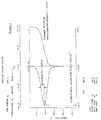
- thermograms In Fig. 1, the right part of the picture shows the boiling curve, the left part of the picture shows the first derivative of the boiling curve after time. Since the heating rate is kept constant, for example 1 Kelvin per minute, the boiling loss per unit of time is equivalent to the boiling loss per Kelvin temperature increase. If the boiling loss is divided by the initial weight, the evaporation rate ( ⁇ ) results. The evaporation rate ( ⁇ ) is the definite integral below the evaporation rate in the temperature range under consideration.
- Said prediction of the evaporation rate ( ⁇ ) of the oil residue requires, in addition to the boiling curve, knowledge of the basic composition of the rolling oil and / or fatty oil used, or at least knowledge of the quantity distribution of the main components.
- the supplier must provide this information, but also information about changing the recipe. By periodically monitoring the boiling behavior of the oils both at the supplier and The user must ensure the stability of the relevant product properties and ensure the reproducibility of the process. It is also common, for example, to alloy the oil with polar additives. Such a measure proves to be particularly effective when rolling with an emulsion.
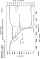
- the oil residue on the cold-rolled strip unaffected by the rolling parameters, will consist almost exclusively of residues of the fatty oil, not residues of the emulsion oil.
- the composition of the oil residue and thus the boiling behavior show no significant fluctuations over longer periods.
- thermograms in Fig. 3 The results of examinations are compared, between which there is a period of 16 months.
- FIG. 4 shows the side view of the inlet part of the glow line in longitudinal section as the first special exemplary embodiment of the cleaning device according to the invention.
- the belt 1 is guided into the cleaning part 4 separated by the inlet lock 2 and outlet lock 3 against the ambient air or against the adjacent furnace atmosphere.
- the latter is equipped with nozzle bars 11 and radiant heating tubes 7 arranged successively above and below the belt.
- the belt is moved on driven support rollers 6 through the cleaning part.
- dry protective gas for example a hydrogen / nitrogen mixture in a ratio of four to one, flows in countercurrent through the outlet lock 3 into the cleaning part 4.
- the protective gas is fed through a steam feed 13, which in the rear third of the cleaning section opens below the belt into the furnace, mixed with water vapor.
- the protective gas outlet 18 is located near the inlet lock also below the belt.
- the protective gas in the cleaning part is circulated with a plurality of blowers 8 installed on the furnace and driven by electric motor 15, by suction through a suction line 14 leading through the furnace vault and through the pressure line and nozzle bars 11 and nozzles 12 arranged above and below the belt onto the belt surface is blown.
- two thermocouples 17 are installed in the rear third of the cleaning part, which are expediently guided from above through the vault into the furnace chamber.
- Fig. 5 shows the cross section of the cleaning part with blower 8 and associated electric drive 15, suction line 14, pressure line 9 and the throttle valve 10 built therein for quantity regulation as well as the positioning of the dew point control 16, nozzle bar 11 and nozzles 12, support roller 6 and volume 1 and the steam feed 13.
- claim 8 provide a modified version of the cleaning part according to claim 7 insofar as it is divided into several chambers by locks, whereby the cleaning distance can be shortened or lengthened depending on the belt speed by means of fans and rows of nozzles as well as required in the individual chambers Steam can be switched off or on.
- a temperature below the decomposition temperature of the oil residue is given as the upper limit which the belt temperature may reach before leaving the cleaning part.
- the latter is the temperature at which the vapor pressure, even under isothermal conditions, i.e. without further temperature rise, becomes a time-dependent variable and the vapor pressure increase is by definition 1.87 Pascal per second.
- claims 9 and 11 to 14 provide refinements of the cleaning device which ensure a homogeneous and effective protective gas atmosphere and regulated heating of the belt.
- an embodiment of the nozzle holder in the nozzle bar 11 is specified, through which the nozzles 12 are brought out of the danger zone in the simplest way when threading the beginning of the tape.
- claim 5 is given as an alternative process feature to claim 4, the tape after leaving the cleaning part through the outlet lock 3 in a decarburizing furnace atmosphere with a correspondingly high dew point, which extends the scope of the method to materials that, for example, due to the susceptibility to aging must be subjected to decarburization annealing
- the transport in suspension via a gas cushion generated by blower pressure and nozzles 12 below the belt 1 is specified, which means that for cleaning the usually dirtier belt underside anyway pressure energy brought to a higher level on the underside of the belt is advantageously used for the adjustment of the floating state, so that postponements, scratches and pimples are reliably avoided at least in this stage of heating.
- the features of claim 6 provide a feasible with simple technical means, the environmentally friendly exhaust gas combustion or exhaust gas recovery device, which ensures that only CO2, H2O and N2 occur in the exhaust gas.
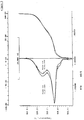
- the boiling curve of the oil residue - weighed in at 5.796 mg, heating rate 10 Kelvin per minute - recorded under technically pure nitrogen with a thermal balance - results in a bimodal distribution of the evaporation rate with the boiling maxima, dominated by the two main components of the oil residue and as well as with the maximum evaporation rates at these temperatures of and 6 shows the boiling curve on which the exemplary embodiment is based. They are transferred to the evaporation behavior under the real furnace atmosphere, taking into account the respectively set H2 / N2 ratio.
- the shift of the boiling maxima to lower temperatures with increasing H2 content is calculated from the relationship with sufficient accuracy for technical purposes: A lowering of the boiling maxima of 46 Kelvin would therefore have to be expected for annealing under 100% hydrogen.
- the evaporation rate ( ⁇ ) can be a good approximation as the sum of the integrals of the two evaporation rates ( ⁇ A ) and ( ⁇ B ) normally distributed over the temperature (T) within the limits given by the strip start temperature (T a ) and the end strip temperature (T e ) being represented.
- T a strip start temperature
- T e end strip temperature
- the mass fractions of the main components A and B of the oil residue have to be named.
- the rolling oil supplier provides the relevant information; As a rule, component A will be the mineral oil component boiling at a lower temperature and component B will be the fatty acid / fatty ester component boiling at a higher temperature.
- the information refers to the fresh oil delivered, it is advisable to check it on the oil residue by determining the saponification number according to DIN 51 559.
- the final strip temperature (T e ) must be defined;
- the material constant ( ⁇ B ) of the oil residue, with the aid of which the temperature at which the evaporation of component B has ended, must be known.
- the position of the nozzle in the cleaning section changes the heating speed ( ⁇ ) of the strip under the gas jet and, in proportion to the heating speed, the vapor pressure (p D ) of the oil film on the surface of the strip.
- the change in vapor pressure with the heating rate in the boiling range of oil components A and B corresponds to their evaporation rates at these temperatures; they component B will be about a factor of 0.0100 / 0.0033 ⁇ 3 larger than component A. This is important insofar as the heating rate ( ⁇ ) decreases with increasing strip temperature (T0); Water vapor feed 10 volume percent: Nozzle position, m 2nd 6 10th 14 18th 22 26 ⁇ , Kelvin / second 146 123 105 90 75 60 46
- the heating speed is reduced, for example, to around half if the value at the nozzle position 14 m is compared with that at the nozzle position 26 m.
- This disadvantage is compensated for by the larger gradient of the vapor pressure rise with the heating speed at the nozzle position 26 m.
- Fig. 7 shows how the minimum shielding gas requirement changes depending on the water vapor content and the nozzle position, indicated by the strip temperature (T0) when entering under the gas jet.
- the conditions in the temperature range between 350 and 750 Kelvin and with a steam input of 10 to 20 percent by volume are shown.
- a constant carbon coating m C 0.5 g / m2 surface of the belt entering the cleaning section is assumed on average. Under these conditions, otherwise as stated above, the shielding gas requirement increases with the strip temperature and decreases with the proportion of water vapor in the shielding gas.
- High strip temperatures (T0), from 664 to 700 Kelvin, and high water vapor proportions between 16 and 20 percent by volume from the point of view of protective gas consumption are considered favorable for the cleaning effect.
- Fig. 8 shows the carbon that can be converted per standard cubic meter of protective gas as a function of the water vapor content and the protective gas temperature (T g ).
- T g protective gas temperature
- the relationships in the temperature range between 800 and 1200 Kelvin and with a steam feed of 1 to 20 percent by volume are shown.
- the oxidation potential ( ⁇ Ox ) compared to carbon grows exponentially with the gas temperature and practically linear with the water vapor content in the protective gas.
- the inert gas circulation should be such that temperature differences in the gas atmosphere are reduced and carbon deposits are avoided.
- the turbulence is intended to promote the conversion of carbon to CO and CO2 until equilibrium is reached. It is therefore important to ensure that the sum of the volume flows of all nozzles connected exceeds the shielding gas throughput at least twice.
- the heat exchange with the belt becomes more intense, the gas will cool down. As the gas temperature drops, the conversion of the carbon according to FIG. 8 will decrease. It is therefore necessary to limit the amount circulated.
- the strip cleanliness and freedom from aging achieved will be used as a benchmark, and the special features of the furnace system and the annealing program such as length of the cleaning part, strip speed, strip dimensions, material, surface condition must be taken into account.
- the circulation rate in the inlet part can be increased without causing the oil film to evaporate there by rotating the nozzles of the front nozzle bars from the vertical position, as in the threading process, so that the gas jet away from the belt surface, for example towards the radiant heating pipes or horizontally.
- the minimum circulation capacity as a function of the water vapor feed-in is determined as follows, in standard cubic meters per hour: Water vapor share,% 10th 15 20th Minimum circulation capacity, m 3rd n /H 1040 700 480
Landscapes
- Chemical & Material Sciences (AREA)
- Engineering & Computer Science (AREA)
- Mechanical Engineering (AREA)
- Chemical Kinetics & Catalysis (AREA)
- General Chemical & Material Sciences (AREA)
- Materials Engineering (AREA)
- Metallurgy (AREA)
- Organic Chemistry (AREA)
- Cleaning And De-Greasing Of Metallic Materials By Chemical Methods (AREA)
Applications Claiming Priority (2)
| Application Number | Priority Date | Filing Date | Title |
|---|---|---|---|
| DE4211457 | 1992-04-06 | ||
| DE4211457 | 1992-04-06 |
Publications (3)
| Publication Number | Publication Date |
|---|---|
| EP0572780A2 true EP0572780A2 (fr) | 1993-12-08 |
| EP0572780A3 EP0572780A3 (fr) | 1994-04-27 |
| EP0572780B1 EP0572780B1 (fr) | 1995-07-26 |
Family
ID=6456166
Family Applications (1)
| Application Number | Title | Priority Date | Filing Date |
|---|---|---|---|
| EP93105667A Expired - Lifetime EP0572780B1 (fr) | 1992-04-06 | 1993-04-06 | Procédé et dispositif pour nettoyer des surfaces de bandes métalliques par balayage à gaz dans une atmosphère enrichie en hydrogène |
Country Status (2)
| Country | Link |
|---|---|
| EP (1) | EP0572780B1 (fr) |
| DE (1) | DE59300400D1 (fr) |
Cited By (9)
| Publication number | Priority date | Publication date | Assignee | Title |
|---|---|---|---|---|
| DE19840778A1 (de) * | 1998-09-07 | 2000-03-09 | Messer Griesheim Gmbh | Verfahren und Vorrichtung zur Reinigung von Metalloberflächen |
| WO2013017783A1 (fr) | 2011-08-03 | 2013-02-07 | L'air Liquide,Societe Anonyme Pour L'etude Et L'exploitation Des Procedes Georges Claude | Procédé de préparation de surfaces d'aluminium ou d'étain/chrome par traitement par plasma atmosphérique pour le dépôt de revêtements sans promoteurs d'adhérence |
| CN108220585A (zh) * | 2017-12-06 | 2018-06-29 | 包头钢铁(集团)有限责任公司 | 退火方法、退火系统和罩式炉 |
| PL421956A1 (pl) * | 2017-06-20 | 2019-01-02 | Przedsiębiorstwo Wielobranżowe Omega Spółka Jawna Łukasz Sosnowski, Bogusław Stempień | Sposób i układ do odtłuszczania oraz zabezpieczania antykorozyjnego taśm lub arkuszy wykonanych z metali lub ich stopów |
| CN113874166A (zh) * | 2019-05-29 | 2021-12-31 | 应用材料公司 | 使用蒸汽用于预热或清洁cmp部件 |
| CN114060834A (zh) * | 2021-10-11 | 2022-02-18 | 佛山市三水凤铝铝业有限公司 | 一种喷涂挂具清理装置及其清理方法 |
| CN114729413A (zh) * | 2019-11-12 | 2022-07-08 | 斯佩拉有限公司 | 经调节的箔材热处理 |
| CN115667557A (zh) * | 2020-05-29 | 2023-01-31 | Sms集团有限公司 | 用于对非晶粒取向的电工钢带进行再结晶退火的方法 |
| US12459011B2 (en) | 2019-05-29 | 2025-11-04 | Applied Materials, Inc. | Steam treatment stations for chemical mechanical polishing system |
Families Citing this family (1)
| Publication number | Priority date | Publication date | Assignee | Title |
|---|---|---|---|---|
| CN104759476B (zh) * | 2015-04-29 | 2017-06-13 | 中冶南方工程技术有限公司 | 一种冷轧带钢表面清洁装置及方法 |
Family Cites Families (5)
| Publication number | Priority date | Publication date | Assignee | Title |
|---|---|---|---|---|
| DE3325198C2 (de) * | 1983-07-13 | 1998-10-29 | Schloemann Siemag Ag | Verfahren und Anordnung zum Reinigen von kaltgewalzten Metallbändern |
| FR2562562B1 (fr) * | 1984-04-04 | 1986-08-08 | Stein Heurtey | Procede et dispositif de nettoyage en continu d'une bande metallique |
| DE8603098U1 (de) * | 1986-02-06 | 1986-03-27 | Gebr. Bellmer GmbH + Co KG Maschinenfabrik, 7532 Niefern | Reinigungsvorrichtung für ein Endlosband |
| DE3639657A1 (de) * | 1986-11-20 | 1988-06-01 | Philips Patentverwaltung | Verfahren zum reinigen von metallbauteilen fuer kathodenstrahlroehren |
| DE3734200A1 (de) * | 1987-10-09 | 1989-04-27 | Kliro Bau Gmbh & Co Kg | Verfahren und vorrichtung zum entfernen anhaftenden schmiermittels von werkstuecken |
-
1993
- 1993-04-06 EP EP93105667A patent/EP0572780B1/fr not_active Expired - Lifetime
- 1993-04-06 DE DE59300400T patent/DE59300400D1/de not_active Expired - Fee Related
Cited By (12)
| Publication number | Priority date | Publication date | Assignee | Title |
|---|---|---|---|---|
| DE19840778A1 (de) * | 1998-09-07 | 2000-03-09 | Messer Griesheim Gmbh | Verfahren und Vorrichtung zur Reinigung von Metalloberflächen |
| WO2013017783A1 (fr) | 2011-08-03 | 2013-02-07 | L'air Liquide,Societe Anonyme Pour L'etude Et L'exploitation Des Procedes Georges Claude | Procédé de préparation de surfaces d'aluminium ou d'étain/chrome par traitement par plasma atmosphérique pour le dépôt de revêtements sans promoteurs d'adhérence |
| PL421956A1 (pl) * | 2017-06-20 | 2019-01-02 | Przedsiębiorstwo Wielobranżowe Omega Spółka Jawna Łukasz Sosnowski, Bogusław Stempień | Sposób i układ do odtłuszczania oraz zabezpieczania antykorozyjnego taśm lub arkuszy wykonanych z metali lub ich stopów |
| PL232443B1 (pl) * | 2017-06-20 | 2019-06-28 | Przed Wielobranzowe Omega Spolka Jawna Lukasz Sosnowski Boguslaw Stempien | Sposób i układ do odtłuszczania oraz zabezpieczania antykorozyjnego taśm lub arkuszy wykonanych z metali lub ich stopów |
| CN108220585A (zh) * | 2017-12-06 | 2018-06-29 | 包头钢铁(集团)有限责任公司 | 退火方法、退火系统和罩式炉 |
| CN113874166A (zh) * | 2019-05-29 | 2021-12-31 | 应用材料公司 | 使用蒸汽用于预热或清洁cmp部件 |
| US12459011B2 (en) | 2019-05-29 | 2025-11-04 | Applied Materials, Inc. | Steam treatment stations for chemical mechanical polishing system |
| CN114729413A (zh) * | 2019-11-12 | 2022-07-08 | 斯佩拉有限公司 | 经调节的箔材热处理 |
| CN115667557A (zh) * | 2020-05-29 | 2023-01-31 | Sms集团有限公司 | 用于对非晶粒取向的电工钢带进行再结晶退火的方法 |
| US20230212708A1 (en) * | 2020-05-29 | 2023-07-06 | Sms Group Gmbh | Method for recrystallisation annealing of a non-grain-oriented electric strip |
| CN114060834A (zh) * | 2021-10-11 | 2022-02-18 | 佛山市三水凤铝铝业有限公司 | 一种喷涂挂具清理装置及其清理方法 |
| CN114060834B (zh) * | 2021-10-11 | 2023-12-26 | 佛山市三水凤铝铝业有限公司 | 一种喷涂挂具清理装置及其清理方法 |
Also Published As
| Publication number | Publication date |
|---|---|
| DE59300400D1 (de) | 1995-08-31 |
| EP0572780A3 (fr) | 1994-04-27 |
| EP0572780B1 (fr) | 1995-07-26 |
Similar Documents
| Publication | Publication Date | Title |
|---|---|---|
| DE69704732T2 (de) | Verfahren zum Beizen von Stahlwerkstücken, insbesondere Blechband aus rostfreiem Stahl | |
| DE2010471C3 (de) | Verfahren zum Aufbringen von Flußmittel und zum Verlöten von Werkstücken aus Aluminium oder Aluminiumlegierungen und in diesem Verfahren hergestellte Wärmetauscher | |
| DE69606270T2 (de) | Wässerige Lösung zur Kaltverfestigungsbehandlung von Stahlblechen | |
| EP0572780B1 (fr) | Procédé et dispositif pour nettoyer des surfaces de bandes métalliques par balayage à gaz dans une atmosphère enrichie en hydrogène | |
| DE3785661T2 (de) | Verfahren zur herstellung eines nichtalternden feuerverzinkten stahlbleches. | |
| DE3015461C2 (de) | Verfahren zum durchlaufgluehen eines kaltgewalzten niedriggehkohlten stahlbandes | |
| DE102005012296A1 (de) | Verfahren und Vorrichtung zum Entzundern eines Metallbandes | |
| DE10252178A1 (de) | Verfahren und Vorrichtung zum Entzundern und/oder Reinigen eines Metallstrangs | |
| DE3028285A1 (de) | Verfahren zum saeubern von metallbaendern und -blechen beim kaltwalzen | |
| DE68917109T2 (de) | Verfahren und Vorrichtung zur Vorbehandlung von kalt zu wälzendem rostfreiem Stahlband. | |
| DE2904318C2 (de) | Verfahren zum Sintern von Preßkörpern aus Metallpulver | |
| DE2537298B2 (de) | Verfahren zur Vorbehandlung eines Kohlenstoffstahlbandes oder- bleches vor dem fluBmittelfreien Feuermetallisieren | |
| DE2830702C2 (de) | Verfahren zur Erzeugung eines Überzugs aus Reinaluminium auf Stahlröhren geringen Durchmessers | |
| DE69509527T2 (de) | Verfahren zum ätzen von metallischen werkstoffen | |
| DE2359020A1 (de) | Verfahren und einrichtung zur waermebehandlung von fortlaufendem metallgut mittels elektrischer widerstandserhitzung | |
| DE2614800A1 (de) | Legierung zum verzinnen von aluminium, sowie verfahren und vorrichtung zur verwendung dieser legierung | |
| EP0647723B1 (fr) | Procédé pour la fabrication de tuyaux d'installation en cuivre durs ou demi-durs, étirés sans soudure | |
| DE2951818A1 (de) | Verfahren zur fortlaufenden kuehlbehandlung von metallischen werkstuecken, insbesondere blechen | |
| DE3028195A1 (de) | Verfahren zur herstellung von rohren, rohre nach diesem verfahren und anwendung derartiger rohre | |
| DE954607C (de) | Verfahren zum Entkohlen der Oberflaechenschichten von Werkstuecken aus Eisen oder Stahl | |
| DE2929401A1 (de) | Verfahren zum walzen von in der waerme zur oxidation neigenden metallbloecken zu rohren | |
| DE2337022A1 (de) | Verfahren zur reinigung der innenflaeche von kupferrohren zur vermeidung der durch einen kohlenstoffueberzug bedingten korrosion | |
| DE69510091T2 (de) | Verfahren zur Wärmebehandlung von rostfreiem Stahl | |
| DE68906593T2 (de) | Verfahren zur verhinderung des bleiziehens. | |
| DE1521422B2 (de) | Verfahren zur kontinuierlichen Her stellung von mit einer Schutzschicht aus Metall, wie Zink, Aluminium und derglei chen, überzogenen Stahlbandern |
Legal Events
| Date | Code | Title | Description |
|---|---|---|---|
| PUAI | Public reference made under article 153(3) epc to a published international application that has entered the european phase |
Free format text: ORIGINAL CODE: 0009012 |
|
| AK | Designated contracting states |
Kind code of ref document: A2 Designated state(s): BE DE FR GB IT SE |
|
| PUAL | Search report despatched |
Free format text: ORIGINAL CODE: 0009013 |
|
| AK | Designated contracting states |
Kind code of ref document: A3 Designated state(s): BE DE FR GB IT SE |
|
| 17P | Request for examination filed |
Effective date: 19940707 |
|
| 17Q | First examination report despatched |
Effective date: 19940104 |
|
| GRAA | (expected) grant |
Free format text: ORIGINAL CODE: 0009210 |
|
| AK | Designated contracting states |
Kind code of ref document: B1 Designated state(s): BE DE FR GB IT SE |
|
| REF | Corresponds to: |
Ref document number: 59300400 Country of ref document: DE Date of ref document: 19950831 |
|
| GBT | Gb: translation of ep patent filed (gb section 77(6)(a)/1977) |
Effective date: 19950807 |
|
| ITF | It: translation for a ep patent filed | ||
| ET | Fr: translation filed | ||
| PLBE | No opposition filed within time limit |
Free format text: ORIGINAL CODE: 0009261 |
|
| 26N | No opposition filed | ||
| REG | Reference to a national code |
Ref country code: GB Ref legal event code: IF02 |
|
| PGFP | Annual fee paid to national office [announced via postgrant information from national office to epo] |
Ref country code: FR Payment date: 20030423 Year of fee payment: 11 |
|
| PGFP | Annual fee paid to national office [announced via postgrant information from national office to epo] |
Ref country code: SE Payment date: 20030429 Year of fee payment: 11 |
|
| PGFP | Annual fee paid to national office [announced via postgrant information from national office to epo] |
Ref country code: GB Payment date: 20030430 Year of fee payment: 11 |
|
| PGFP | Annual fee paid to national office [announced via postgrant information from national office to epo] |
Ref country code: BE Payment date: 20030514 Year of fee payment: 11 |
|
| PG25 | Lapsed in a contracting state [announced via postgrant information from national office to epo] |
Ref country code: GB Free format text: LAPSE BECAUSE OF NON-PAYMENT OF DUE FEES Effective date: 20040406 |
|
| PG25 | Lapsed in a contracting state [announced via postgrant information from national office to epo] |
Ref country code: SE Free format text: LAPSE BECAUSE OF NON-PAYMENT OF DUE FEES Effective date: 20040407 |
|
| PG25 | Lapsed in a contracting state [announced via postgrant information from national office to epo] |
Ref country code: BE Free format text: LAPSE BECAUSE OF NON-PAYMENT OF DUE FEES Effective date: 20040430 |
|
| PGFP | Annual fee paid to national office [announced via postgrant information from national office to epo] |
Ref country code: DE Payment date: 20040602 Year of fee payment: 12 |
|
| BERE | Be: lapsed |
Owner name: *EBG G.- FUR ELEKTROMAGNETISCHE WERKSTOFFE M.B.H. Effective date: 20040430 |
|
| GBPC | Gb: european patent ceased through non-payment of renewal fee | ||
| EUG | Se: european patent has lapsed | ||
| PG25 | Lapsed in a contracting state [announced via postgrant information from national office to epo] |
Ref country code: FR Free format text: LAPSE BECAUSE OF NON-PAYMENT OF DUE FEES Effective date: 20041231 |
|
| REG | Reference to a national code |
Ref country code: FR Ref legal event code: ST |
|
| PG25 | Lapsed in a contracting state [announced via postgrant information from national office to epo] |
Ref country code: IT Free format text: LAPSE BECAUSE OF NON-PAYMENT OF DUE FEES Effective date: 20050406 |
|
| PG25 | Lapsed in a contracting state [announced via postgrant information from national office to epo] |
Ref country code: DE Free format text: LAPSE BECAUSE OF NON-PAYMENT OF DUE FEES Effective date: 20051101 |