EP0572798A2 - Dispositif pour la mesure sans contact d'un objet tridimensionnel - Google Patents
Dispositif pour la mesure sans contact d'un objet tridimensionnel Download PDFInfo
- Publication number
- EP0572798A2 EP0572798A2 EP93106867A EP93106867A EP0572798A2 EP 0572798 A2 EP0572798 A2 EP 0572798A2 EP 93106867 A EP93106867 A EP 93106867A EP 93106867 A EP93106867 A EP 93106867A EP 0572798 A2 EP0572798 A2 EP 0572798A2
- Authority
- EP
- European Patent Office
- Prior art keywords
- carrier
- optical
- deflection
- recording
- reflected
- Prior art date
- Legal status (The legal status is an assumption and is not a legal conclusion. Google has not performed a legal analysis and makes no representation as to the accuracy of the status listed.)
- Withdrawn
Links
Images






Classifications
-
- G—PHYSICS
- G01—MEASURING; TESTING
- G01B—MEASURING LENGTH, THICKNESS OR SIMILAR LINEAR DIMENSIONS; MEASURING ANGLES; MEASURING AREAS; MEASURING IRREGULARITIES OF SURFACES OR CONTOURS
- G01B11/00—Measuring arrangements characterised by the use of optical techniques
- G01B11/24—Measuring arrangements characterised by the use of optical techniques for measuring contours or curvatures
-
- A—HUMAN NECESSITIES
- A61—MEDICAL OR VETERINARY SCIENCE; HYGIENE
- A61C—DENTISTRY; APPARATUS OR METHODS FOR ORAL OR DENTAL HYGIENE
- A61C9/00—Impression cups, i.e. impression trays; Impression methods
- A61C9/004—Means or methods for taking digitized impressions
- A61C9/0046—Data acquisition means or methods
- A61C9/0053—Optical means or methods, e.g. scanning the teeth by a laser or light beam
-
- G—PHYSICS
- G01—MEASURING; TESTING
- G01B—MEASURING LENGTH, THICKNESS OR SIMILAR LINEAR DIMENSIONS; MEASURING ANGLES; MEASURING AREAS; MEASURING IRREGULARITIES OF SURFACES OR CONTOURS
- G01B11/00—Measuring arrangements characterised by the use of optical techniques
- G01B11/24—Measuring arrangements characterised by the use of optical techniques for measuring contours or curvatures
- G01B11/25—Measuring arrangements characterised by the use of optical techniques for measuring contours or curvatures by projecting a pattern, e.g. one or more lines, moiré fringes on the object
- G01B11/2518—Projection by scanning of the object
-
- G—PHYSICS
- G01—MEASURING; TESTING
- G01B—MEASURING LENGTH, THICKNESS OR SIMILAR LINEAR DIMENSIONS; MEASURING ANGLES; MEASURING AREAS; MEASURING IRREGULARITIES OF SURFACES OR CONTOURS
- G01B11/00—Measuring arrangements characterised by the use of optical techniques
- G01B11/24—Measuring arrangements characterised by the use of optical techniques for measuring contours or curvatures
- G01B11/25—Measuring arrangements characterised by the use of optical techniques for measuring contours or curvatures by projecting a pattern, e.g. one or more lines, moiré fringes on the object
- G01B11/2518—Projection by scanning of the object
- G01B11/2522—Projection by scanning of the object the position of the object changing and being recorded
-
- A—HUMAN NECESSITIES
- A61—MEDICAL OR VETERINARY SCIENCE; HYGIENE
- A61C—DENTISTRY; APPARATUS OR METHODS FOR ORAL OR DENTAL HYGIENE
- A61C7/00—Orthodontics, i.e. obtaining or maintaining the desired position of teeth, e.g. by straightening, evening, regulating, separating, or by correcting malocclusions
- A61C7/002—Orthodontic computer assisted systems
-
- A—HUMAN NECESSITIES
- A61—MEDICAL OR VETERINARY SCIENCE; HYGIENE
- A61C—DENTISTRY; APPARATUS OR METHODS FOR ORAL OR DENTAL HYGIENE
- A61C9/00—Impression cups, i.e. impression trays; Impression methods
- A61C9/004—Means or methods for taking digitized impressions
Definitions
- the invention relates to a device for the contactless measurement of an inaccessible, three-dimensional object optically by creating flat recordings, with an optical beam source, a recording unit for recording optical beams and an evaluation unit for evaluating the information transmitted by the optical beams.
- the accessibility of the object to be measured is so unfavorable that there is no direct visibility of the object, at least from the point of view required for the measurement.
- the reason mostly lies in the spatial limitation for the measuring device, so that in other words the space around the object to be measured is so small that neither the measuring device nor sufficiently large optics with deflecting mirrors and the like are arranged or housed for carrying out the measurement can.
- Tooth misalignments should be corrected with the help of the "Edge-Wise-wire arch technique".
- holding elements so-called brackets
- This is shaped in such a way that it exerts the required correction forces and moments on the brackets and thus on the teeth.
- the wire arch In order to set the correct forces and moments, the wire arch must be set correctly, specifically for each patient at each treatment level, a specially made wire arch. It has already been proposed to use computer-controlled bending machines to create the correctly shaped wire arches. For this, at least the spatial coordinates of the brackets must be known exactly. Accurate data on the occlusal surfaces of the teeth would also be helpful for the practitioner, because the goal of tooth correction is to achieve a tooth position in which the occlusal surfaces of the corresponding teeth of the upper and lower jaw are correctly aligned.
- the invention is therefore based on the object of providing a device for measuring the type mentioned at the outset, with which it is possible to measure objects even in confined spaces without contact, with precise spatial spacing and to record the data of the measurement results.
- a deflection device for rays reflected on the object is arranged in this room, it can be directed to a recording unit and detected there. So far there has been a problem that the object is not completely could be illuminated and / or detected in a single mirror, so that special optical methods for spatial measurement were not used.
- the invention overcomes this problem by using a carrier which is movable relative to the object and to which a deflection device is attached, with which the beams are directed to a recording unit, where the data can be stored and evaluated to create the spatial data sought.
- the location of the deflection device with respect to the object is known exactly at every moment of the measurement or in every position of the carrier.
- Known measuring devices can be used for this or the task can be solved constructively.
- the movable carrier is guided exactly and carries a fixed or adjustable deflection device.
- the device can be used to carry out various measurement methods, a light source for visible light generally being used as the beam source, and even the object in a special case described later generally illuminating radiation source can be used.
- the deflection device in addition to the object, can possibly also detect and detect only a partial area of the object to be measured and move it over the object surface to be measured, in individual steps or continuously, by means of the movement of the carrier is that several sub-areas are scanned and measured with the result of sub-data areas or sub-images, which can then be put together easily and from which one can possibly put together a spatial representation of the object. It must be ensured that the position of the guide device relative to the object to be measured is known stes.
- a rigid coupling or a fixed connection can be provided, but the coupling can also consist of a form-fitting connection without a direct connection. It only has to be possible to measure and know the exact location of the wearer via his guide unit to the object.
- the evaluation unit is able to store the data or partial images completely and then evaluate them with the aid of the location of the deflection device with respect to the object (with the aid of the measuring devices mentioned). It is also possible to carry out a preliminary evaluation immediately after the information or data has been recorded in order to reduce the amount of data to be stored.
- the recording unit (s) and / or the radiation source (s) immovably, provided that the latter is / are required for generating directed beams, that is to say not to travel with the carrier.
- This embodiment variant is deliberately covered by the invention, although in the description of preferred embodiments it is assumed that such an application in which the recording unit and the beam source travel.
- the device according to the invention is a flat (two-dimensional) measurement of the object, also in the so-called 3D measurement, in which ultimately two (or more) flat recordings are taken, which are evaluated together, only the flat one can be taken Measure an object that is difficult to access.
- the information of the temporal course of the position and orientation of the deflection device with respect to the object is evaluated.
- This position is formed from the information of the position and direction of the base frame relative to the object and the position and orientation of the carrier relative to the base frame.
- the information relating to the two-dimensional recording of the at least one image of the object can be provided, which result from the optical rays reflected by the object when the deflection unit is moved relative to the object.
- Linear or rotary sensors can be used for the measuring devices for determining the position of the carrier and the moved (oscillating or rotating) mirrors, if their position is not known in any case by a control path.
- the guideway is designed in a straight line as a non-rotating linear guide and the carrier as a linear slide. This results in particularly simple conditions for the drive and measurement.
- the guideway can also be circular and the carrier can be designed as a swivel flap.
- At least one further deflection unit is provided for the oscillating deflection of the optical beam reflected by the object in a further spatial direction and for projecting the same into the recording unit.
- line-shaped image information can be recorded with a point-shaped recording unit for each position and orientation of the first deflection unit.
- flat image information can be obtained for each position and orientation of the first deflection unit.
- a rotating mirror is provided for deflecting the optical beam reflected by the object and if the rotating mirror is attached to the carrier in such a way that the axis of rotation of the rotating mirror is orthogonal (perpendicular) to the direction of movement of the carrier.
- An optical beam with very little divergence and small diameter can be projected onto the object via mirrors, and if a rotating mirror is interposed, which preferably has several mirror planes arranged at angles to one another, then these mirror surfaces can be designed in such a way that the optical beam covers the whole Brushed object width to be measured.
- the rotary movement of the rotating mirror can also be achieved by mechanical coupling with the movement of the carrier.
- Such coupling can e.g. be realized by a non-traveling rack arranged on the carrier guide, into which a gearwheel mounted in the carrier engages, which drives the rotating mirror via a gear.
- CCD area chips or CCD line chips can also be used as the recording unit.
- a rotating mirror as mentioned above, one can also work with a surface chip in another embodiment, in which case there is no need to know the angular position of the rotating mirror, since this serves only for the lateral deflection of the illumination beam and this deflection on the Chip is recognizable.
- an oscillating mirror could also be used.
- the deflection device can be pivotable, for example, so that the rays reflected from the object at an angle to one another are directed to the recording unit one after the other.
- the device can be very advantageous if, in the presence of only one receiving unit, it is adjustable in height and / or angle. Then the device can then be brought into the correct position in order to receive the desired beam projected by the deflection device.
- a light beam expanded in one plane can be provided, which after linear reflection on the object is attached to the support via at least one.
- a plane mirror is directed into the recording unit having an area camera. This avoids the oscillating pivoting of the optical beam and thus the "traversing" of the line by the beam.
- By expanding the beam in the line plane a thin, straight line can be projected onto the object from the point of view of the beam source. If the location of the camera, preferably an area camera, is outside the expansion plane of the beam, the spatial coordinates can be determined for each point illuminated by the line - that is, for a complete line - in a similar manner to that described above for the light point projection method.
- a straight line is projected onto the object surface, which from the point of view of the recording unit (depending on the height differences of the surface) appears to be more or less curved. Accordingly, in the point projection method, the deflection of the point is more or less strong from the point of view of the recording unit.
- the mirror surface for the recording beams is advantageously chosen to be so large (high) that the resulting deflection of the line or point is completely visible.
- this deflection is very large due to the height differences of the area to be measured and the height of the deflecting mirror is too large, it makes sense to make the two deflecting units separately movable for directional lighting and recording.
- the deflection unit for the lighting would be moved in the certain small steps, and with each new position of this unit the deflection unit for the receptacle (again in individual steps) would be moved in such a way that the entire necessary surface is coated.
- the recording unit can then be designed as a line camera, and on the other hand the height of the recording mirror can be reduced.
- the beams can be given a punctiform and / or linear and / or any pattern.
- a further deflection unit for deflecting the optical beam in at least one plane.
- a moving deflection device rotary, translatory or free kinematics
- the stereo imaging method is suitable. At least two partial images are generated for this.
- the deflection device can be provided for at least two beams, which are directed from the object at an angle to one another and to the object, and the recording unit has devices for the separate storage and evaluation of the beams generated from the two separate beams at least two drawing files. It is not absolutely necessary for the stereo recording method to generate a directed optical beam with low divergence and to direct it onto the object. Rather, it may be sufficient to adequately illuminate the object with general brightness.
- this represents only one of the arbitrary number of beams illuminating the object, namely that which leads to the correspondingly viewed beam reflected by the object.
- the entirety of the rays directed towards the object (which illuminates the object surface) then leads to a multiplicity of rays reflected by the object, which together form a partial image.
- the one partial image is generated by a certain central beam which is at a first angle to the object; and the second partial image is generated by a specific second beam which is at a specific second angle to the object, the two specific beams being directed at an angle to one another.
- the deflection device generates, for example, a top view of the object in the receiving optics, while on the other hand an oblique view of the object is generated.
- the top view is only a special case. It is only important that you have two different diagonal views. Both views, ie both partial images, are recorded in the recording unit. For example, the points of these partial images are imaged on a CCD area chip by means of a camera lens, so that electronic data are available separately for each partial image. These can then be saved and evaluated in such a way that the spatial data can be called up. Two different complete images can be put together for the two different views from the recorded and stored partial images. These correspond, for example, to the top view and the oblique view. It is known how to calculate the height coordinates of the respective points from the different coordinates of the detected distinctive points in the top view and in the oblique view.
- the recording unit can also have two row chips if the carrier is moved in correspondingly small steps.
- the object or its partial view can either be projected onto two row chips arranged next to one another by means of a single lens, or onto the two row chips, which are then to be spatially separated, using two separate lenses, if necessary using a beam splitter.
- CCD cameras line and area cameras
- tube cameras or cameras that work with film material can be used to record image information, in the latter case the necessary evaluation of the recorded partial images can be more complex.
- a CCD line camera one can also use a light-sensitive element to record a single point, e.g. a photodiode when mechanical line scanning, e.g. by a rotating or oscillating mirror.
- the measuring and evaluation devices described in the device according to the invention for carrying out the stereo imaging method allow particularly prominent points on object surfaces to be measured, in the case of dental technology e.g. Points on holding elements for orthodontics.
- a grid is arranged between the beam source and the object.
- this can be a grid or any other grid area, such as a glass plate with an etched pattern.
- a grid can thus advantageously be projected onto the object surface, so that the number of points to be measured can be increased in accordance with the fineness of the grid.
- Dot patterns, grid areas etc. create striking dots when using static directional lighting.
- the projection of transverse lines i.e. perpendicular to the direction of travel
- This height profile is very useful for measuring the occlusal surfaces in dental technology.
- the 3D information can also be obtained by projecting points or lines or patterns onto the surface of the object at a different angle, namely when using moving directional lighting.
- the projection of the points or lines is a separate task and in no way has to be done by means of a deflecting lens attached to the carrier.
- a second carrier is also conceivable, which carries the deflecting optics for the projection.
- a human dentition is to be measured for orthodontic purposes, it is sufficient, on the one hand, to measure a few striking points (in this case, the brackets) - for which the stereo imaging method is suitable - and on the other hand, a relatively rough line grid of the surface (in the case of the occlusal surface of the teeth), for which the light section method lends itself.
- the device according to the invention characterized in that, in addition to the beam source for generating an optical beam widened in one plane, a recording unit having an area camera and at a distance therefrom are arranged a deflection device which is attached to the carrier and which for at least two, directed at an angle to one another and to the object, from Object reflected rays is provided.
- the two partial images are produced over the entire length of the object, and moreover, a quantity of data is obtained by driving over, measuring and evaluating the thin line, which is projected onto the object using the light section method.
- Another embodiment of the invention is characterized by a deflection device attached to a further carrier for directing the optical beam toward the object, this further carrier being able to be moved separately on a further path.
- a deflection device attached to a further carrier for directing the optical beam toward the object, this further carrier being able to be moved separately on a further path.
- a separate support can be provided for both the illuminating side and the receiving side.
- Another preferred embodiment of the device according to the invention has a deflecting device for directing the optical beam toward the object, this deflecting device being fastened to the carrier for the receiving deflecting unit and being movable together with the latter.
- this deflecting device being fastened to the carrier for the receiving deflecting unit and being movable together with the latter.
- a separate carrier with drive etc. is therefore provided for each unit.
- the optical beam can also be directed to the object directly by means of the receiving deflection unit instead of through its own deflection device.
- a rotating mirror is attached to the carrier in such a way that the axis of rotation of the rotating mirror is orthogonal to the direction of movement of the carrier.
- the rotating mirror is characterized by the rotating movement. This movement is understood to mean a continuous or intermittent turning in one direction or an oscillating turning in opposite directions.
- the mirror of course ensures the deflection of the optical beam.
- the rotating mirror can be attached to the carrier common for the illuminating side and the reflecting side.
- the rotating mirror is preferably used both to deflect the directed projection beam and to deflect the beam used for recording.
- the invention is also advantageously configured in that the beam source has devices for generating an optical beam widened in one plane and the deflection device is formed for directing the line-shaped reflected beam on the object in the recording unit having a surface camera.
- the deflection device has at least one plane mirror attached to the carrier.
- the deflection device has two plane mirrors attached to the carrier at different angles.
- Such a deflection device can be spatially compact and can be defined and simply moved by the carrier.
- the beam direction of the optical source is fixed at an angle to the optical axis of the recording unit, the deflection device preferably having a plane mirror attached to the carrier. If the spatial conditions allow this arrangement, the required angle between the beam from the optical source and the recording axis of the camera results directly and automatically, and both the projection of the beam onto the object and the recording of the projected line can be done using the same single plan mirror.
- the evaluation unit has devices for forming 3D information from the directed optical irradiation of the object.
- the possibility of simultaneously measuring the upper and lower jaw can be created by doubling the active elements of the deflection device. If necessary, the beam sources and recording units must then also be doubled.
- the use of the device of the above-described embodiments for contactless measurement of at least one tooth of a bit and / or of the position and / or shape of at least one holding element for orthodontic wires, so-called brackets, which is attached to the tooth is particularly favorable.
- the measuring device according to the invention described above generates two images of the object from different views when using the stereo imaging method. The measurement of prominent points in both views enables the spatial coordinates of these points to be determined.
- brackets with which wire arches are held, markings for orthodontic treatment and / or their shape selected so that automatic detection is possible.
- markings can be printed, etched, recessed or raised, for example.
- an auxiliary measuring body provided with suitable dimensions and surfaces is provided for insertion into the central groove of the holding element.
- the described device according to the invention for the optical measurement of orthodontic wire holding elements enables the use of a computer-controlled bending or twisting machine for adapting the wire arch to the current denture shape of the patient.
- a computer-controlled bending or twisting machine for adapting the wire arch to the current denture shape of the patient.
- both their position and the relaxed shape of the wire arch to be used are known.
- the forces and moments acting on the holding elements due to the elastic deformation of the wire arch used can be precisely predetermined or selected by means of the calculation methods known from statics.
- the square cross-section of 0.41 mm ⁇ 0.41 mm which is customary among other things, is sufficient to apply the required forces and moments to a wire arch which can be precisely adapted with the device according to the invention.
- the wire holding elements previously used in orthodontics are generally not sufficiently suitable for simple or automatable optical measurement. In this case, it makes sense to use the measurement auxiliary bodies mentioned in the holding elements (brackets) for the measurement instead of the wire arch, the shape and design of which enable easy identification.
- the carrier of the measuring device according to the invention is preferably driven by a stepping or servo motor, but can also be done by a Maltese cross or by a simple ratchet mechanism, as in film projectors. It is also possible to use a drive in conjunction with a position measuring system, so that the current location of the wearer can be determined.
- the consideration applies that the smaller the process steps from one recording position to the next, the smaller the area of the object to be detected, and the smaller the necessary height of the deflecting mirror, so that the required Height of the measuring device can be reduced. This reduction is limited by the fact that an extreme reduction in the deflection mirror creates the effect of a slit diaphragm, with the result that the required illuminance increases.
- the length of the process steps is preferably adapted to the possible resolution of a light-sensitive surface in the recording unit. When using a CCD camera, it makes sense to design the process steps so that a process step on the image plane corresponds to the line spacing of the chip, so that only one chip line per mirror view is evaluated. In practice, movement steps for the wearer in the range between 1/100 to 1 mm have been used as expedient. A step length of 1/10 mm is particularly preferred in orthodontics.
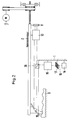
- the measuring device of FIG. 1 is only shown schematically in order to simplify the description and for better comprehensibility without known, obvious device parts.
- a support 4 which can be moved in a straight line in the direction of the double arrow 3, is mounted via a ball guide 2 and is mounted in motion with a spindle 5.
- This is driven by a motor 7 (stepping or servo motor) also attached to the base frame 1.
- a motor 7 stepping or servo motor
- 7 ′ illustrates an integrated measuring system that may be provided for the motor 7.
- the object 9 is shown here as a surface connected to the base frame 1 with three-dimensional extensions, e.g. it could be the row of teeth of a human dentition.
- the carrier 4 extends in the direction of the mouth opening at a close distance from the object 9, and it is easy to imagine that the carrier with its superstructures can be accommodated in the region of the object 9 within the oral cavity.
- In this area there are two plane mirrors 12 and 13 positioned at different angles to one another and to the object 9, while at the other end of the elongated support 4, ie outside the oral cavity, the receiving device is attached to the support, in the present case a camera lens 10 with a CCD area chip 11.
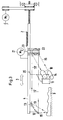
- the embodiments of the measuring device according to FIGS. 2 and 2a have the same structure, which is why the same parts are not numbered there.
- a special feature is a beam source 14 also attached to the base frame 1, which in the embodiment of Figure 1 and analog embodiments is a beam source for generating "general brightness" because it e.g. in the embodiment of FIG. 1, it is sufficient that the surface of the object 9 is bright and can emit reflected rays.
- the beam source 14 is shown separately as one for generating directed beams. In Figure 2, this beam is shown as a dash-dotted line and designated 15.
- the specific embodiments described here are light rays from the visible range. (Alternatively, one can also imagine rays in the infrared or umtraviolet range with corresponding transmission and reception devices).
- the beam source 14 contains a lens system (not shown in more detail), and a grid 17 or a grid is arranged between this and a further lens system 16 in such a way that its projection onto the surface of the object 9 succeeds in producing striking points on the surface.
- This grid 17 can also be a glass plate with etched patterns.
- FIG. 2a Another similar alternative to the embodiment is shown in FIG. 2a, in which the grid 17 is fastened to the base frame 1 directly above the surface of the object 9, so that, for example, a shadow pattern is cast onto the object surface by means of appropriate optics.
- arrow 3 is to be thought of as lying in an X axis.
- An imaginary Y-axis runs perpendicular to this X-axis and perpendicular to the plane of the drawing.
- the appropriate illumination of the surface of the object 9 generates reflected rays and leads it to the recording unit 10, 11.
- the reflected beam 18 (top view) extends perpendicular to a main surface in the X-Y plane onto the outer plane mirror 12, where it is deflected and guided in the form of the reflected beam 18 ′ into the objective 10 and with a suitable image onto the surface chip 11. This creates a first drawing.
- another reflected beam 19 is directed to the plane mirror 13 and, after being deflected as beam 19 ', is likewise guided to the camera lens 10.
- the beam 18 'thus forms a top view in the receiving unit 10, 11, and with the other mirror 13 an oblique view is formed by the reflected beam 19'.
- the electronic processing of the output signal of the chip 11, which is not further described here, enables the two partial images to be stored and evaluated separately.
- due to the described drive of the carrier 4, its respective exact location and thus that of the deflection device 12, 13 relative to the object 9 is known.
- the recorded and saved partial images are put together to form two complete images, which correspond to the images of the top view and the oblique view.
- the height coordinates can be calculated from the different coordinates of prominent points in the two views.
- the carrier 4 is preferably displaced in small steps of 1/10 mm in the direction of the double arrow 3, for example from the back to the front, i.e. in the figures from left to right for measuring from an initial position (left) to the end position (right), in which the reflected rays 18 and 19 originate from the rightmost edge of the object 9 shown in the figures.
- the evaluation unit is designated 11 a and is connected to the chip 11. Although it is only shown in FIG. 1, it should also be thought of in the other embodiments.
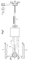
- the carrier 4 On the rear outer end of the carrier 4 there are again the two mirrors 12 and 13, and moving along with the carrier 4 are further to the right on the fastening rod indicated by 20 (only schematically) the light source 14 and above that the camera lens 10 with the CCD arranged behind it -Line chip 11 attached.
- a rotary mirror 22 is attached to the carrier 4 so that it can move along by means of a second stepping or servo motor 21 in such a way that the axis 23 of the rotary mirror 22 is perpendicular to the linear translatory movement according to double arrow 3.
- the beam with low divergence and small diameter 15 directed by the beam source 14 is deflected at the rotating mirror 22 and strikes the outer plane mirror 12 as a beam 15 ', which throws this beam onto the surface of the object 9, from where it is similar to that in FIG. 1 guided as a reflected beam 19 to the other plane mirror 13 and deflected there and guided as a beam 19 'onto the rotating mirror 22, where it is deflected and directed into the objective 10.
- the rays are deflected via the rotating mirror 22 with the indicated several mirror surfaces.
- the beam can be pivoted in an oscillating manner in at least one plane such that the light beam 15 ′, after deflection via the plane mirror 12, sweeps the entire width of the object 9 to be measured.
- the reflected beam 19 ' is also recorded via the rotating mirror 22. This means that it is sufficient to use only a vertical CCD line chip 11, onto which the light spot is projected via the camera lens 10.
- the current angular position of the rotating mirror 22 and thus also the information at which point on the line the scanning is currently taking place is exactly known.
- the rotating mirror 22 shown in FIG. 3 thus fulfills two functions: on the one hand, the beam 15 generated in the beam source (here light source) 14 is deflected laterally (oscillatingly pivotable), and on the other hand the beam 19, 19 'reflected by the object 9 is also deflected via the the same mirror surface of the rotating mirror 22 is steered back into the camera optics 10, so that, from the point of view of the camera, the lateral deflection of the beam 15 'projected onto the object is not noticeable. For this reason, this lateral deflection (measured via the instantaneous angle of rotation of the mirror 22) must be known for the computational processing.
- the projection of the projected light spot can take place via a camera, which is aimed directly at the plane mirror 13.
- a camera which is aimed directly at the plane mirror 13.
- an area camera would have to be used, since both the lateral deflection of the beam, which is caused by the rotating mirror 22, and the height deflection appearing in the plane mirror 13 must be recorded.
- the lateral deflection of the beam which is visible directly in the camera (chip camera 11), eliminates the need to measure the instantaneous angle of rotation of the rotating mirror 22.
- FIG. 5 shows another embodiment of the measuring device for the light section method.
- Various recording methods can also be described on the basis of this FIG. 5.
- the light section method is described with reference to Figures 4 and 4a.
- the perspective view in FIG. 4a shows the widened beam 15 which comes from the beam source 14 and above it the reflected, widened beam 19 'which is guided into the camera 10.
- the beam source 14 generates a light beam as in the light spot projection described above, but this beam is widened in the plane shown in FIG. 4a below, so that a thin line 24 is projected onto the object 9 via the rear plane mirror 12, which is projected over the other plane mirror 13 is recorded by the camera 10, 11 as a reflected beam plane 19 '.
- the use of an area camera is necessary, because the thin line 24 projected onto the object only appears as a straight line in the top view of the beam 15 ′ that is incident vertically from above, and is a curved line in the direction of the reflected beams.
- the arrangement of the light source 14 with respect to the camera lens 10 can also take place at a different angle, in which case the expanded beam 15 is then directed onto the rear, outer plane mirror 12 at a required angle via deflection mirrors and / or beam splitters, not shown.
- the light section method can also be used as a deflection device using only a single plane mirror 12 '. If the spatial conditions permit such an arrangement, as shown in FIG. 5, then the required angle between the beam source 14 and the recording axis (parallel to the beam 19 ') of the camera 10, 11 results directly. The projection of the light beam 15, 15 'onto the object 9 can thus also take place via the same plane mirror 12', as can the recording of the projected line 19 '.
- the advantage of the light section method of being able to measure all points on a surface is offset by the condition of the higher amount of data that arises when recording, because for each line to be scanned, that is, with step-by-step drive for each process step of the carrier 4, a flat image must be recorded. With the stereo imaging method, the recording of a single line is sufficient.
- FIG. 6 The embodiment in FIG. 6 is essentially the same device as that in FIG. 1.
- a beam source 14 generating a directed beam is arranged, which, similar to the embodiment in FIG. 4, generates an expanded light beam 15 .
- This widened light beam 15 is projected again onto the surface of the object 9 via the outer plane mirror 12.
- this light section method is combined with the stereo image method, so that reflected rays 19, 19 'are also received by the recording unit 10, 11 via the foremost inner plane mirror 13' or, alternatively, rays 25 reflected by the object surface and after reflection at the central deflecting plane mirror 13 the rays 25 'are recorded.
- a stereo image is thus again recorded via the plane mirrors 13 and 13 ', for which purpose two plane mirrors are required.
- the arrangement of the optical axis of one objective or of both objectives at an angle to the direction of the beam source can also make do with only a single plane mirror 13 or 13 '.
- FIG. 7 shows a device similar to FIG. 1, but only the measuring conditions are doubled.
- This embodiment is used for the simultaneous measurement of the upper and lower jaw of a bit 9, 9 '.
- this is rigidly coupled to the base frame 1, e.g. by touching or clamping, because the teeth are attached to the jaw and not on the base plate 1 shown only schematically here under the object 9 and above the object 9 '.
- the measuring device described above can improve the optical recognizability of the already mentioned holding elements 26 (so-called brackets).
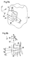
- FIG. 8 shows the row of teeth consisting of three teeth 27, a holding element 26 being applied in each case to the outer surface of the tooth 27 via adhesive surfaces 28.
- the holding element has the mushroom shape shown in cross section in FIG. 8b (in the Z-Y plane of FIG. 8a), the holding element 26 being penetrated by a central groove 29 on the outside in its longitudinal direction (X direction). This serves to receive the wire arch 41.
- Hook-shaped webs 30 adjoin the center groove 29 on both sides, around which a rubber ring 31 in the left-hand illustration of FIG. 8 is fastened or folded over for fastening the wire arch 41 to the holding element 26.
- the X, Y and Z coordinates of the holding element 26 and its angular position about the Y and Z axes result. From the distance of these points 31 from the edge of the holding element, which appears as a line in the projection of the Z direction and is represented by the boundary line 32 in FIG. 8b (or 32 'for a different dimension), the angular position results from the X-axis, represented in FIG. 8b by the angles ⁇ 1 or ⁇ 2 or ⁇ 3.
- the contour of the outer surface of the holding element 26, that is to say the surface facing away from the tooth 27, can be selected such that there is an anatomically sensible angular range for everyone measured horizontal distance A1 or A2 or A3 ( Figure 8b) from the outer surface of the holding element, the line according to projection 32 or 32 ', etc., to the marking points results in a clearly assigned angular position.
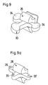
- FIGS. 9 and 9a Two different embodiments of auxiliary measuring bodies 33 and 33 'can be seen from FIGS. 9 and 9a.
- the measuring auxiliary body 33 has a T-shape in plan view with rounded thickenings 34 at the ends of the legs.
- the thickness of the auxiliary measuring body corresponds to the height of the central groove 29 and is formed by two parallel planes spaced apart from one another.
- the auxiliary measuring bodies are plate-shaped in the X-Y plane and have a flat, flat surface.
- the leg ends are designed without the thickenings mentioned in the embodiment of FIG. 9, that is to say simply in the form of a T in plan view in the Z direction of the auxiliary measuring body 33'.
- Both the partial circular rounding of the auxiliary measuring body 33 'in plan view and the thickened embodiment 34 in the auxiliary measuring body according to FIG. 9 determine an outer contour, through which three center points can be measured. The position of the holding element 26 can then again be clearly determined from the spatial coordinates of these three center points. Alternatively, instead of the center points, markings 35 can also be made on the ends of the legs, as is indicated in the auxiliary measuring body 33 'in FIG. 9a.
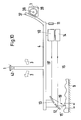
- FIG. 10 shows another embodiment for the application of the device for the light section method. Reference can also be made here to FIG. 4.
- the carrier 4 is mounted on the pivot point 42 in the base frame 1. Accordingly, it executes a rotary movement according to the two arrows 3 pointing in the opposite direction.
- the drive is carried out here via a toothed segment 37, which is firmly connected to the carrier 4.
- the pinion 38 of a geared motor 39 engages in this toothed segment 37.
- the geared motor 39 is preferably designed as a stepping motor with a reduction gear, but can also be a servo motor with a reduction gear.
- Motor 39 is also attached to the base frame 1.
- the deflection device executes a movement on a circular arc around the pivot point 42, so that the distance to the object 9 also changes in the geometrical relationships shown. This is not disadvantageous if only a small area (indicated on object 9 with the double arrow at the bottom left) is to be measured, for example a single tooth.
- the required swivel angle of the carrier 4 would only be small, and the change in the distance of the deflection device from the object surface would also be correspondingly small.
- FIG. 10a Another embodiment is shown in FIG. 10a, in which the deflection device likewise executes a rotary movement.
- the pivot point 42 is brought very close to the deflection unit via the base frame 1, which here is a stationary, elongated rod.
- the carrier 4 is only a small, short lever, which carries the deflection device.
- the drive takes place via a push rod 43, which is driven analogously to FIG. 10 via a geared motor.
Landscapes
- Physics & Mathematics (AREA)
- General Physics & Mathematics (AREA)
- Engineering & Computer Science (AREA)
- Computer Vision & Pattern Recognition (AREA)
- Health & Medical Sciences (AREA)
- Epidemiology (AREA)
- Oral & Maxillofacial Surgery (AREA)
- Dentistry (AREA)
- Optics & Photonics (AREA)
- Life Sciences & Earth Sciences (AREA)
- Animal Behavior & Ethology (AREA)
- General Health & Medical Sciences (AREA)
- Public Health (AREA)
- Veterinary Medicine (AREA)
- Length Measuring Devices By Optical Means (AREA)
- Dental Tools And Instruments Or Auxiliary Dental Instruments (AREA)
Applications Claiming Priority (2)
| Application Number | Priority Date | Filing Date | Title |
|---|---|---|---|
| DE4218219 | 1992-06-03 | ||
| DE4218219A DE4218219C2 (de) | 1992-06-03 | 1992-06-03 | Vorrichtung zum berührungslosen Vermessen eines schlecht zugänglichen, dreidimensionalen medizinischen oder zahntechnischen Objektes |
Publications (2)
| Publication Number | Publication Date |
|---|---|
| EP0572798A2 true EP0572798A2 (fr) | 1993-12-08 |
| EP0572798A3 EP0572798A3 (fr) | 1995-05-17 |
Family
ID=6460258
Family Applications (1)
| Application Number | Title | Priority Date | Filing Date |
|---|---|---|---|
| EP93106867A Withdrawn EP0572798A3 (fr) | 1992-06-03 | 1993-04-28 | Dispositif pour la mesure sans contact d'un objet tridimensionnel. |
Country Status (4)
| Country | Link |
|---|---|
| US (1) | US5424836A (fr) |
| EP (1) | EP0572798A3 (fr) |
| CA (1) | CA2097554A1 (fr) |
| DE (1) | DE4218219C2 (fr) |
Cited By (6)
| Publication number | Priority date | Publication date | Assignee | Title |
|---|---|---|---|---|
| FR2758076A1 (fr) * | 1997-01-09 | 1998-07-10 | Sabban Joseph Cohen | Procede et dispositif optoelectroniques de retrodigitalisation en odontologie |
| GB2371111A (en) * | 2001-01-16 | 2002-07-17 | Teraprobe Ltd | Investigating and scanning a sample |
| WO2011095175A1 (fr) * | 2010-02-08 | 2011-08-11 | 3Shape A/S | Système d'alimentation d'objets |
| WO2012152261A1 (fr) * | 2011-05-11 | 2012-11-15 | Friedrich-Schiller-Universität Jena | Procédé de mesure 3d d'objets |
| CN107072762A (zh) * | 2015-05-06 | 2017-08-18 | 北京大学口腔医学院 | 一种口腔探测、数据处理装置和方法及口腔探测系统 |
| CN110621259A (zh) * | 2017-03-09 | 2019-12-27 | 马辛宾科夫斯基N-实验室 | 口腔内扫描装置、这种装置的操作方法以及扫描器系统 |
Families Citing this family (38)
| Publication number | Priority date | Publication date | Assignee | Title |
|---|---|---|---|---|
| WO1995004254A1 (fr) * | 1993-07-29 | 1995-02-09 | Fraunhofer-Gesellschaft zur Förderung der angewandten Forschung e.V. | Dispositif de mesure tridimensionnelle pour cavites inaccessibles |
| SE512621C2 (sv) * | 1993-12-06 | 2000-04-10 | Nobel Biocare Ab | Metod och kamera för stereofotografering av tänder |
| JP3513936B2 (ja) * | 1993-12-22 | 2004-03-31 | 松下電工株式会社 | 光走査型変位測定装置 |
| GB2292605B (en) * | 1994-08-24 | 1998-04-08 | Guy Richard John Fowler | Scanning arrangement and method |
| FI98757C (fi) * | 1995-05-31 | 1997-08-11 | Tamglass Eng Oy | Menetelmä taivutetun lasilevyn taipumisasteen mittaamiseksi |
| US5646733A (en) * | 1996-01-29 | 1997-07-08 | Medar, Inc. | Scanning phase measuring method and system for an object at a vision station |
| US6009189A (en) * | 1996-08-16 | 1999-12-28 | Schaack; David F. | Apparatus and method for making accurate three-dimensional size measurements of inaccessible objects |
| DE19636354A1 (de) | 1996-09-02 | 1998-03-05 | Ruedger Dipl Ing Rubbert | Verfahren und Vorrichtung zur Durchführung von optischen Aufnahmen |
| US5815274A (en) * | 1996-12-31 | 1998-09-29 | Pitney Bowes Inc. | Method for dimensional weighing by spaced line projection |
| DE19733709B4 (de) * | 1997-08-04 | 2005-08-11 | Leitz Messtechnik Gmbh | Optischer Tastkopf für 3D-Koordinatenmeßgeräte |
| DE19829278C1 (de) * | 1998-06-30 | 2000-02-03 | Sirona Dental Systems Gmbh | 3-D-Kamera zur Erfassung von Oberflächenstrukturen, insbesondere für zahnmedizinische Zwecke |
| US6553138B2 (en) | 1998-12-30 | 2003-04-22 | New York University | Method and apparatus for generating three-dimensional representations of objects |
| US6413084B1 (en) | 2000-04-28 | 2002-07-02 | Ora Metrix, Inc. | Method and system of scanning |
| US6512994B1 (en) | 1999-11-30 | 2003-01-28 | Orametrix, Inc. | Method and apparatus for producing a three-dimensional digital model of an orthodontic patient |
| US6532299B1 (en) | 2000-04-28 | 2003-03-11 | Orametrix, Inc. | System and method for mapping a surface |
| JP3417377B2 (ja) * | 1999-04-30 | 2003-06-16 | 日本電気株式会社 | 三次元形状計測方法及び装置並びに記録媒体 |
| DE19950780C2 (de) * | 1999-10-21 | 2003-06-18 | Sirona Dental Systems Gmbh | Verfahren und Vorrichtung zur Erfassung medizinischer Objekte, insbesondere von Modellen präparierter Zähne |
| US6540512B1 (en) | 1999-11-30 | 2003-04-01 | Orametrix, Inc. | Method and apparatus for treating an orthodontic patient |
| US6648640B2 (en) | 1999-11-30 | 2003-11-18 | Ora Metrix, Inc. | Interactive orthodontic care system based on intra-oral scanning of teeth |
| US7471821B2 (en) | 2000-04-28 | 2008-12-30 | Orametrix, Inc. | Method and apparatus for registering a known digital object to scanned 3-D model |
| US7027642B2 (en) | 2000-04-28 | 2006-04-11 | Orametrix, Inc. | Methods for registration of three-dimensional frames to create three-dimensional virtual models of objects |
| US6611664B2 (en) * | 2000-06-26 | 2003-08-26 | Kabushiki Kaisha Topcon | Stereo image photographing system |
| DE10132226A1 (de) * | 2001-06-29 | 2003-01-16 | Kpv Ag Bern | Verfahren zur Herstellung einer dreidimensionalen Kopie von einem als Vorlage dienenden Körper und Anlage zur Durchführung des Verfahrens |
| WO2003016819A1 (fr) * | 2001-08-14 | 2003-02-27 | Metronom Gmbh Industrial Measurement | Procede pour mesurer des structures superficielles |
| US6604814B2 (en) * | 2001-09-28 | 2003-08-12 | Hewlett-Packard Development Company, Lp | Arrangements of interconnect circuit and fluid drop generators |
| US6767208B2 (en) | 2002-01-10 | 2004-07-27 | Align Technology, Inc. | System and method for positioning teeth |
| AU2004223469B2 (en) * | 2003-03-24 | 2009-07-30 | D4D Technologies, Llc | Laser digitizer system for dental applications |
| DE102005052294A1 (de) * | 2005-10-26 | 2007-05-03 | Jaruszewski, Lutz, Dr. | Messvorrichtung und Verfahren zur Bestimmung des Aktivitätsstatus initialkariöser Schmelzläsionen |
| KR101043976B1 (ko) | 2009-12-15 | 2011-06-24 | 데오덴탈 주식회사 | 구강용 스캐너 |
| DE102014205784B4 (de) * | 2014-03-27 | 2024-01-18 | Sirona Dental Systems Gmbh | Scanvorrichtung |
| CH709747A1 (de) * | 2014-06-11 | 2015-12-15 | Quarz Partners Ag | Verfahren und Vorrichtung zum dreidimensionalen Ausmessen von Zahnreihen. |
| IL235950A0 (en) * | 2014-11-27 | 2015-02-26 | Imaging Solutions Ltd Ab | 3D scanners for simultaneous acquisition of 3D datasets of 3D objects |
| CN108347545A (zh) * | 2018-03-30 | 2018-07-31 | 深圳积木易搭科技技术有限公司 | 一种双目扫描仪 |
| EP3701908A1 (fr) | 2019-02-28 | 2020-09-02 | Sirona Dental Systems GmbH | Scanner intra-oral 3d |
| CN111297499B (zh) * | 2020-03-21 | 2022-02-08 | 福建新安格口腔技术发展有限公司 | 一种陶瓷金属复合正畸托槽及其制备方法 |
| EP4201372B1 (fr) * | 2021-12-22 | 2024-10-09 | 3Shape A/S | Scanner comprenant un nouveau mécanisme d'entraînement de lentille |
| CN117516408B (zh) * | 2023-09-27 | 2024-06-25 | 苏州佳祺仕科技股份有限公司 | 一种曲面检测装置及磁通检测装置 |
| DE102024200967B4 (de) * | 2024-02-02 | 2026-02-19 | Carl Zeiss Meditec Ag | Verfahren und System zur Erzeugung eines dreidimensionalen Abbilds zumindest eines Teilabschnitts einer Zahnreihe und Computerprogramm |
Family Cites Families (23)
| Publication number | Priority date | Publication date | Assignee | Title |
|---|---|---|---|---|
| DE2903529A1 (de) * | 1979-01-31 | 1980-08-07 | Schlatter Ag | Verfahren zum messen von entfernungen und vorrichtung zur durchfuehrung des verfahrens |
| JPS56100306A (en) * | 1980-01-14 | 1981-08-12 | Fuji Photo Optical Co Ltd | Analyzer for sectional shape of substance |
| JPS57108705A (en) * | 1980-12-26 | 1982-07-06 | Kawasaki Steel Corp | Method and device for monitor of bead cut form at welded part on inner surface of welded tube |
| CH646516A5 (fr) * | 1982-02-25 | 1984-11-30 | Speno International | Procede et dispositif de mesure du profil transversal du champignon d'un rail d'une voie ferree. |
| US4500206A (en) * | 1982-10-15 | 1985-02-19 | The United States Of America As Represented By The Secretary Of The Air Force | Optical system for measuring shadowgraph data |
| JPS6055211A (ja) * | 1983-09-06 | 1985-03-30 | Nec Corp | 非接触三次元測定装置 |
| US4668192A (en) * | 1983-12-16 | 1987-05-26 | Lavin Joseph J | Apparatus and method for executing orthodontic procedure |
| CH672722A5 (fr) * | 1986-06-24 | 1989-12-29 | Marco Brandestini | |
| JPH0799326B2 (ja) * | 1986-08-30 | 1995-10-25 | 株式会社マキ製作所 | 球塊状物品の外観検査方法と装置 |
| GB8626812D0 (en) * | 1986-11-10 | 1986-12-10 | Sira Ltd | Surface inspection |
| JP2794698B2 (ja) * | 1987-10-28 | 1998-09-10 | 興和 株式会社 | 立体形状測定装置 |
| AU598418B2 (en) * | 1988-06-04 | 1990-06-21 | Fujitsu Limited | Optical system for detecting three-dimensional shape |
| DE3829925C2 (de) * | 1988-09-02 | 1994-03-03 | Kaltenbach & Voigt | Vorrichtung zur optischen Vermessung von Zähnen in der Mundhöhle |
| FR2639211A1 (fr) * | 1988-11-18 | 1990-05-25 | Hennson Int | Procede de correlation des saisies tridimensionnelles d'organes humains et dispositif pour sa mise en oeuvre |
| US4935635A (en) * | 1988-12-09 | 1990-06-19 | Harra Dale G O | System for measuring objects in three dimensions |
| JPH0641851B2 (ja) * | 1989-04-05 | 1994-06-01 | 日本鋼管株式会社 | 3次元曲面形状の測定装置 |
| DE3933994A1 (de) * | 1989-10-11 | 1991-05-08 | Kaltenbach & Voigt | Optische sonde zur absoluten 3-dimensionalen vermessung von einzelzaehnen und zahngruppen in der mundhoehle |
| JP2510786B2 (ja) * | 1990-04-14 | 1996-06-26 | 松下電工株式会社 | 物体の形状検出方法及びその装置 |
| DE9004995U1 (de) * | 1990-05-02 | 1991-09-05 | Siemens AG, 80333 München | Als Handinstrument ausgebildete Kamera zur 3D-Vermessung von Zähnen |
| DE4027328B4 (de) * | 1990-08-29 | 2004-07-22 | Sirona Dental Systems Gmbh | 3D-Kamera zur Erfassung von Oberflächenstrukturen, insbesondere für zahnmedizinische Zwecke |
| DE4032871A1 (de) * | 1990-10-17 | 1992-04-23 | Bosch Gmbh Robert | Schaltungsanordnung zur abtastung optischer aufzeichnungstraeger |
| DE4034007C2 (de) * | 1990-10-25 | 2001-05-10 | Sirona Dental Systems Gmbh | Verfahren und Vorrichtung zur optischen Erfassung von Oberflächenstrukturen an Zähnen |
| DE4037383A1 (de) * | 1990-11-20 | 1992-05-21 | Mesacon Messtechnik | Verfahren zum kontinuierlichen beruehrungsfreien messen von profilen und einrichtung zur durchfuehrung des messverfahrens |
-
1992
- 1992-06-03 DE DE4218219A patent/DE4218219C2/de not_active Expired - Fee Related
-
1993
- 1993-04-28 EP EP93106867A patent/EP0572798A3/fr not_active Withdrawn
- 1993-06-02 US US08/070,264 patent/US5424836A/en not_active Expired - Lifetime
- 1993-06-02 CA CA002097554A patent/CA2097554A1/fr not_active Abandoned
Cited By (10)
| Publication number | Priority date | Publication date | Assignee | Title |
|---|---|---|---|---|
| FR2758076A1 (fr) * | 1997-01-09 | 1998-07-10 | Sabban Joseph Cohen | Procede et dispositif optoelectroniques de retrodigitalisation en odontologie |
| GB2371111A (en) * | 2001-01-16 | 2002-07-17 | Teraprobe Ltd | Investigating and scanning a sample |
| GB2371111B (en) * | 2001-01-16 | 2005-05-04 | Teraprobe Ltd | Apparatus and method for investigating a sample |
| US7214940B2 (en) | 2001-01-16 | 2007-05-08 | Teraview Limited | Apparatus and method for investigating a sample |
| WO2011095175A1 (fr) * | 2010-02-08 | 2011-08-11 | 3Shape A/S | Système d'alimentation d'objets |
| US9329015B2 (en) | 2010-02-08 | 2016-05-03 | 3Shape A/S | Object feeder system |
| WO2012152261A1 (fr) * | 2011-05-11 | 2012-11-15 | Friedrich-Schiller-Universität Jena | Procédé de mesure 3d d'objets |
| CN107072762A (zh) * | 2015-05-06 | 2017-08-18 | 北京大学口腔医学院 | 一种口腔探测、数据处理装置和方法及口腔探测系统 |
| CN107072762B (zh) * | 2015-05-06 | 2020-07-07 | 北京大学口腔医学院 | 一种口腔探测、数据处理装置和方法及口腔探测系统 |
| CN110621259A (zh) * | 2017-03-09 | 2019-12-27 | 马辛宾科夫斯基N-实验室 | 口腔内扫描装置、这种装置的操作方法以及扫描器系统 |
Also Published As
| Publication number | Publication date |
|---|---|
| US5424836A (en) | 1995-06-13 |
| CA2097554A1 (fr) | 1993-12-04 |
| EP0572798A3 (fr) | 1995-05-17 |
| DE4218219A1 (de) | 1993-12-09 |
| DE4218219C2 (de) | 1998-05-07 |
Similar Documents
| Publication | Publication Date | Title |
|---|---|---|
| DE4218219C2 (de) | Vorrichtung zum berührungslosen Vermessen eines schlecht zugänglichen, dreidimensionalen medizinischen oder zahntechnischen Objektes | |
| EP0519915B1 (fr) | Procede et dispositif de mesure d'un espace, notamment de l'interieur de la bouche | |
| EP3664961B1 (fr) | Fabrication d'un jumeau numérique dans un centre d'usinage | |
| EP0923704B1 (fr) | Procede et dispositif d'obtention d'images par moyens optiques | |
| EP2079981B1 (fr) | Dispositif et procédé pour la mesure sans contact d'un contour tridimensionnel | |
| EP0263316B1 (fr) | Procédé pour déterminer le mouvement relatif au moins en deux dimensions entre une mâchoire supérieure et une mâchoire inférieure et arrangement de mesure pour ce procédé | |
| EP0228500B2 (fr) | Méthode et dispositif pour la mesure sans contact du profil d'une roue des roues d'ensembles de roues de voie ferrée | |
| DE69727632T2 (de) | Dreidimensionale Formmessvorrichtung | |
| DE102008040947B4 (de) | 3D-Dentalkamera zur Erfassung von Oberflächenstrukturen eines Messobjekts mittels Triangulation | |
| EP1725833B1 (fr) | Procede et dispositif pour balayer sans contact des objets tridimensionnels | |
| DE2838555C2 (de) | Vorrichtung zur Ermittlung des Winkels zwischen zwei Körpern | |
| DE102010040386A1 (de) | Dentale Röntgeneinrichtung mit Bilderfassungseinheit zur Oberflächenerfassung und Verfahren zur Erzeugung einer Röntgenaufnahme eines Patienten | |
| WO1992008103A1 (fr) | Procede et dispositif pour le mesurage opto-electronique d'objets | |
| DE3807578C2 (fr) | ||
| EP1757902A1 (fr) | Procédé et dispositif pour mesurer la forme d'un objet dentaire | |
| DE4212404A1 (de) | Vorrichtung zum messen der raeumlichen form eines langgestreckten bauteils | |
| DE3932151A1 (de) | Vorrichtung zur scannenden erfassung eines innenraums | |
| EP2589926A1 (fr) | Dispositif et procédé de mesure optique de la forme d'un objet mobile | |
| EP0447531B1 (fr) | Procede et dispositif pour le mesurage optique tridimensionnel de corps, notamment de dents, dans la cavite buccale d'un patient | |
| DE69426926T2 (de) | Verfahren und vorrichtung zur bildaufnahme des menschlichen körpers, insbesondere der mundhöhle | |
| DE2259762B2 (de) | Verfahren zur automatischen Auswertung von Stereobildern | |
| DE2919027C2 (de) | Schnittbildgerät zur Untersuchung von Objekten nach dem Ultraschall-Schnittbildverfahren | |
| DE4206836C2 (de) | Sonde zur optischen Vermessung von Zähnen | |
| EP0671679A1 (fr) | Méthode et dispositif de mesure sans contact d'objects tri-dimensionnels basé sur la triangulation optique | |
| DE2515975B2 (de) | Verfahren zum automatischen Auswerten von Stereobildern und Vorrichtung zur Durchführung des Verfahrens |
Legal Events
| Date | Code | Title | Description |
|---|---|---|---|
| PUAI | Public reference made under article 153(3) epc to a published international application that has entered the european phase |
Free format text: ORIGINAL CODE: 0009012 |
|
| AK | Designated contracting states |
Kind code of ref document: A2 Designated state(s): AT BE CH DE DK ES FR GB GR IE IT LI LU MC NL PT SE |
|
| 17P | Request for examination filed |
Effective date: 19940429 |
|
| PUAL | Search report despatched |
Free format text: ORIGINAL CODE: 0009013 |
|
| RAP3 | Party data changed (applicant data changed or rights of an application transferred) |
Owner name: GEYER MEDIZIN- UND FERTIGUNGSTECHNIK GMBH |
|
| AK | Designated contracting states |
Kind code of ref document: A3 Designated state(s): AT BE CH DE DK ES FR GB GR IE IT LI LU MC NL PT SE |
|
| 17Q | First examination report despatched |
Effective date: 19960724 |
|
| GRAG | Despatch of communication of intention to grant |
Free format text: ORIGINAL CODE: EPIDOS AGRA |
|
| GRAG | Despatch of communication of intention to grant |
Free format text: ORIGINAL CODE: EPIDOS AGRA |
|
| GRAH | Despatch of communication of intention to grant a patent |
Free format text: ORIGINAL CODE: EPIDOS IGRA |
|
| 18D | Application deemed to be withdrawn |
Effective date: 19980929 |