EP0572802A1 - Dispositif de rajustage pour freins de véhicules - Google Patents
Dispositif de rajustage pour freins de véhicules Download PDFInfo
- Publication number
- EP0572802A1 EP0572802A1 EP93106955A EP93106955A EP0572802A1 EP 0572802 A1 EP0572802 A1 EP 0572802A1 EP 93106955 A EP93106955 A EP 93106955A EP 93106955 A EP93106955 A EP 93106955A EP 0572802 A1 EP0572802 A1 EP 0572802A1
- Authority
- EP
- European Patent Office
- Prior art keywords
- driver
- worm shaft
- housing
- adjustment device
- release sleeve
- Prior art date
- Legal status (The legal status is an assumption and is not a legal conclusion. Google has not performed a legal analysis and makes no representation as to the accuracy of the status listed.)
- Granted
Links
Images




Classifications
-
- F—MECHANICAL ENGINEERING; LIGHTING; HEATING; WEAPONS; BLASTING
- F16—ENGINEERING ELEMENTS AND UNITS; GENERAL MEASURES FOR PRODUCING AND MAINTAINING EFFECTIVE FUNCTIONING OF MACHINES OR INSTALLATIONS; THERMAL INSULATION IN GENERAL
- F16D—COUPLINGS FOR TRANSMITTING ROTATION; CLUTCHES; BRAKES
- F16D65/00—Parts or details
- F16D65/38—Slack adjusters
- F16D65/40—Slack adjusters mechanical
- F16D65/52—Slack adjusters mechanical self-acting in one direction for adjusting excessive play
- F16D65/60—Slack adjusters mechanical self-acting in one direction for adjusting excessive play for angular adjustment of two concentric parts of the brake control systems
Definitions
- the invention relates to an automatic adjustment device for vehicle brakes with a housing serving as a brake lever, in which an adjusting gear consisting of worm and worm wheel is arranged, which works together via a coupling with spur gears and a drive member with a fixed lever protruding into the housing, one of which Spur toothing on the worm shaft and the other spur toothing is arranged on a coupling ring which is displaceable axially displaceably and rotatably against a compression spring, and the worm shaft on the coupling-side end can be manually turned back against the direction of rotation of the adjustment.
- the object of the invention is to further develop the known adjusting device in such a way that the adjustment and resetting can take place from the outside without having to open the housing in the area of the worm shaft.
- a rotatably mounted driver in the housing in front of the worm shaft, which is supported on the housing with one end face and is connected to the worm shaft on the other end face, a release sleeve between the driver and the coupling ring to be arranged, which is mounted axially displaceably but non-rotatably on the worm shaft, and to arrange a disengaging device between the driver and the disengaging sleeve, with which the disengaging sleeve can be axially displaced against the coupling ring by rotating the driver in order to open the clutch.
- the driver can engage with claws in the form of annular sections between claws of the worm shaft in the form of annular sections, wherein there is play between the stop faces of the claws in the size of a necessary disengagement angle for the clutch.
- the torque for adjustment and resetting is transmitted from the outside to the worm shaft via the driver after uncoupling.
- a rotatably mounted driver in the housing in front of the worm shaft, which is supported on the housing with an end face, to arrange a release sleeve between the driver and the coupling ring, which is axially displaceably but non-rotatably mounted on the worm shaft is to arrange a release device between the driver and the release sleeve, with which the release sleeve is axially displaceable in the coupling ring by rotating the driver to the To open the clutch, and to couple the driver and the release sleeve to one another via the release device.
- the torque for adjustment and resetting after the uncoupling is transmitted from the outside to the worm shaft via the driver and the release sleeve.
- the disengaging device expediently consists of at least one notch with an inclined surface which is embedded in the end face of the disengaging sleeve on the driver side and a cam arranged on the jacket of the driver.
- the torque is transmitted from the outside via the driver to the worm shaft as soon as the release play between the claws is closed
- the torque is transmitted via the interposed release sleeve, in which stop surfaces for at both ends of the notch the driver's cams are provided.
- pins are provided on the end face of the worm shaft or on the underside of the driver for fastening a return spring, which has its legs engages in slots of the driver in the first embodiment and rests on projections of the release sleeve in the second embodiment.
- an adjustment device designed according to the invention has the advantage that the housing does not have to be opened for adjustment and resetting, because all the functions required for this can be carried out by simply rotating the driver.
- the driver can be supported on a cover screwed into the housing, which has a small opening. Under this opening in the cover, the driver either has an Allen key for inserting a key or it protrudes from the opening with a profiled head piece on which a key can be inserted.
- the adjustment and turning back of an adjusting device of the type here is hardly imaginable more easily.
- a brake linkage consists of a membrane cylinder 2 fastened to an axle body 1 with a piston rod 3 which engages on a brake lever 4 which is fastened on a brake shaft (not shown). Due to the movement of the piston rod 3, the brake cams can be rotated in a drum brake and the brake shoes or the brake pads can thus be brought into contact with a brake drum.
- a housing 5 is connected with covers 6, 7, in which an adjusting device is arranged to compensate for brake pad wear.
- the adjusting device consists of a worm 9 arranged on a worm shaft 8 and a worm wheel 10 fastened on the brake shaft (not shown) with an internal toothing.
- a coupling 11 is arranged on one side in the housing 5 and consists of a coupling ring 12 mounted on the worm shaft 8 with end teeth 13 and end teeth 15 arranged on the underside of a worm shaft head 14.
- the two spur gears 13, 15 are held in engagement with a compression spring 16 arranged on the worm shaft 8.
- a lever 17 On one side of the housing 5 there is a lever 17 which is guided into the housing 5 with a sleeve 18 under the cover 6 and at the other end has a ring 19 with a stop cam 20 which is in a recess 21 in the housing 5 engages.
- the stop cam 20 and the recess 21 limit the maximum stroke of the brake lever 4 in relation to the lever 17, which is connected to a fixed part of the vehicle, for example the axle body 1.
- a flat drive member 22 is arranged between the sleeve 18 of the lever 17 and the coupling ring 12 and engages on the one hand with a round head 23 in the sleeve 18 and on the other hand with a hook 24 in a recess 25 of the coupling ring 12.
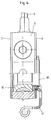
- the worm shaft 8 In order to adjust the readjustment device after changing the lining, the worm shaft 8 has to be turned back by hand against the direction of rotation of the readjustment direction. For this purpose, the coupling 11 between the two spur gears 13, 15 must be opened. 7 to 21 and 22 to 36 two different embodiments of devices for uncoupling and adjusting have been shown.
- a driver 26 is arranged in front of the worm shaft head 14, which is supported on the one hand under an annular cover 27, which in FIG the housing 5 is screwed in, and on the other hand engages with claws 28 in the form of annular sections between claws 29 in the form of annular sections on the worm shaft head 14.
- a release sleeve 30 is axially displaceably mounted on the worm shaft head 14, which is supported on the one hand on the driver 26 and on the other hand on the coupling ring 12.
- the two cams 32 lie in the valley of the notches with the inclined surfaces 31.
- the two cams 32 press the release sleeve 30 against the action of the compression spring 16 inwards and thus release the clutch 11 because the clutch ring 12 also moves inwards.
- the worm shaft 8 on the head 33 of the driver 26 can be turned back into the starting position. The torque is transmitted from the driver 26 to the worm shaft via the claws 28, 29.
- a return spring 35 is attached to the pin 34 of the worm shaft head 14, which engages with its legs in slots 36 of the driver 26.
- the embodiment of the adjusting device according to FIGS. 22 to 36 differs from the embodiment described above essentially in that the torque when resetting is not transmitted directly from the driver 26 to the worm shaft 8, but indirectly via the release sleeve 30.
- the inclined surfaces 31 have a stop 37 at the end of their slope , on which the cams 32 of the driver 26 get caught and take the release sleeve 30 with them.
- the claws 28, 29 on the worm shaft head 14 and under the driver 26 are missing. Since the release sleeve 30 is guided axially displaceably in corresponding grooves on the worm shaft head 14 in both embodiments, the torque is released indirectly after the clutch 11 is released transfer the release sleeve to the worm shaft 8. Otherwise, the functions of both embodiments are the same.
- the return spring 35 attached to the pin 34 of the driver 26 bears against the wedges 38 of the release sleeve 30.
- a seal 39 is arranged between the annular cover 27 and the driver 26 in order to prevent dust from penetrating into the interior of the adjusting device.
- Reference symbol list 1 Axle beam 31 Sloping surface 2nd Membrane cylinder 32 cam 3rd Piston rod 33 head 4th Brake lever 34 Cones 5 casing 35 Return spring 6 cover 36 slot 7 cover 37 attack 8th Worm shaft 38 wedge 9 slug 39 poetry 10th Worm wheel 11 clutch 12th Clutch ring 13 Spur toothing 14 Worm shaft head 15 Spur toothing 16 Compression spring 17th lever 18th Sleeve 19th ring 20th Stop cam 21 Recess 22 Driver 23 head 24th hook 25th Recess 26 Carrier 27th cover 28 claw 29 claw 30th Release sleeve
Landscapes
- Engineering & Computer Science (AREA)
- General Engineering & Computer Science (AREA)
- Mechanical Engineering (AREA)
- Braking Arrangements (AREA)
- Gear Transmission (AREA)
Applications Claiming Priority (2)
| Application Number | Priority Date | Filing Date | Title |
|---|---|---|---|
| DE4218251 | 1992-06-03 | ||
| DE4218251A DE4218251C1 (de) | 1992-06-03 | 1992-06-03 | Nachstellvorrichtung für Fahrzeugbremsen |
Publications (2)
| Publication Number | Publication Date |
|---|---|
| EP0572802A1 true EP0572802A1 (fr) | 1993-12-08 |
| EP0572802B1 EP0572802B1 (fr) | 1996-01-03 |
Family
ID=6460274
Family Applications (1)
| Application Number | Title | Priority Date | Filing Date |
|---|---|---|---|
| EP93106955A Expired - Lifetime EP0572802B1 (fr) | 1992-06-03 | 1993-04-29 | Dispositif de rajustage pour freins de véhicules |
Country Status (2)
| Country | Link |
|---|---|
| EP (1) | EP0572802B1 (fr) |
| DE (2) | DE4218251C1 (fr) |
Cited By (3)
| Publication number | Priority date | Publication date | Assignee | Title |
|---|---|---|---|---|
| WO2003046402A1 (fr) * | 2001-11-29 | 2003-06-05 | Obschestvo S Dopolnitelnoi Otvetstvennostju 'diskoms' | Regulateur de freinage pour vehicule de transport |
| EP1640632A3 (fr) * | 2004-09-22 | 2008-08-27 | BPW Bergische Achsen KG | Capteur d'usure pour un frein d'un véhicule |
| DE102017126953A1 (de) | 2017-11-16 | 2019-05-16 | Bpw Bergische Achsen Kg | Antriebs- und Nachstellvorrichtung einer Trommelbremse |
Families Citing this family (1)
| Publication number | Priority date | Publication date | Assignee | Title |
|---|---|---|---|---|
| DE102005053303B4 (de) * | 2005-11-09 | 2021-04-08 | Bpw Bergische Achsen Kg | Vorrichtung zur Anzeige des Verschleißzustandes von Fahrzeugbremsen |
Citations (5)
| Publication number | Priority date | Publication date | Assignee | Title |
|---|---|---|---|---|
| US3526303A (en) * | 1969-02-12 | 1970-09-01 | Autoset Corp | Automatic brake slack adjuster |
| DE2813841A1 (de) * | 1977-03-31 | 1978-10-05 | Eaton Corp | Anordnung zum selbsttaetigen einstellen des luftspalts zwischen zwei relativ zueinander beweglichen reibungsgliedern |
| EP0154799A2 (fr) * | 1984-03-15 | 1985-09-18 | Bergische Achsenfabrik Fr. Kotz & Söhne | Dispositif de rajustage pour freins de véhicule |
| DE4036311A1 (de) * | 1989-11-14 | 1991-05-16 | Mecapal Sa | Trommelbremse |
| EP0319693B1 (fr) * | 1987-12-08 | 1991-11-13 | Bergische Achsenfabrik Fr. Kotz & Söhne | Dispositif de rajustage pour freins de véhicule |
Family Cites Families (1)
| Publication number | Priority date | Publication date | Assignee | Title |
|---|---|---|---|---|
| DE4017949A1 (de) * | 1990-06-05 | 1991-12-12 | Wabco Westinghouse Fahrzeug | Einrichtung zum selbsttaetigen nachstellen einer bremse, insbesondere fahrzeugbremse |
-
1992
- 1992-06-03 DE DE4218251A patent/DE4218251C1/de not_active Expired - Fee Related
-
1993
- 1993-04-29 DE DE59301294T patent/DE59301294D1/de not_active Expired - Fee Related
- 1993-04-29 EP EP93106955A patent/EP0572802B1/fr not_active Expired - Lifetime
Patent Citations (5)
| Publication number | Priority date | Publication date | Assignee | Title |
|---|---|---|---|---|
| US3526303A (en) * | 1969-02-12 | 1970-09-01 | Autoset Corp | Automatic brake slack adjuster |
| DE2813841A1 (de) * | 1977-03-31 | 1978-10-05 | Eaton Corp | Anordnung zum selbsttaetigen einstellen des luftspalts zwischen zwei relativ zueinander beweglichen reibungsgliedern |
| EP0154799A2 (fr) * | 1984-03-15 | 1985-09-18 | Bergische Achsenfabrik Fr. Kotz & Söhne | Dispositif de rajustage pour freins de véhicule |
| EP0319693B1 (fr) * | 1987-12-08 | 1991-11-13 | Bergische Achsenfabrik Fr. Kotz & Söhne | Dispositif de rajustage pour freins de véhicule |
| DE4036311A1 (de) * | 1989-11-14 | 1991-05-16 | Mecapal Sa | Trommelbremse |
Cited By (3)
| Publication number | Priority date | Publication date | Assignee | Title |
|---|---|---|---|---|
| WO2003046402A1 (fr) * | 2001-11-29 | 2003-06-05 | Obschestvo S Dopolnitelnoi Otvetstvennostju 'diskoms' | Regulateur de freinage pour vehicule de transport |
| EP1640632A3 (fr) * | 2004-09-22 | 2008-08-27 | BPW Bergische Achsen KG | Capteur d'usure pour un frein d'un véhicule |
| DE102017126953A1 (de) | 2017-11-16 | 2019-05-16 | Bpw Bergische Achsen Kg | Antriebs- und Nachstellvorrichtung einer Trommelbremse |
Also Published As
| Publication number | Publication date |
|---|---|
| DE59301294D1 (de) | 1996-02-15 |
| DE4218251C1 (de) | 1993-10-14 |
| EP0572802B1 (fr) | 1996-01-03 |
Similar Documents
| Publication | Publication Date | Title |
|---|---|---|
| DE69518933T2 (de) | Bremsbetätigungsmechanismus für einen Bremssattel | |
| EP0635654B1 (fr) | Dispositif de rajustage pour un frein à disque | |
| EP0614025B1 (fr) | Dispositif de rajustage pour un frein à disque | |
| EP0790431A1 (fr) | Dispositif d'application d'un frein à disque, en particulier pour véhicules utilitaires lourds | |
| EP0154799B1 (fr) | Dispositif de rajustage pour freins de véhicule | |
| DE3241914C2 (de) | Mechanisch bei Überlast ausrückbare Reibscheiben-Kupplung | |
| DE2346828A1 (de) | Nachstellvorrichtung fuer bremsen | |
| EP0572802B1 (fr) | Dispositif de rajustage pour freins de véhicules | |
| DE1605298A1 (de) | Radbremseinheit fuer Schienenfahrzeuge | |
| EP0158034B1 (fr) | Dispositif de rattrapage de jeu pour freins de véhicule | |
| DE3625107C1 (en) | Automatic adjusting device for the expansion cams of a drum brake | |
| EP0319693B1 (fr) | Dispositif de rajustage pour freins de véhicule | |
| DE2605372A1 (de) | Spielnachstellvorrichtung fuer fahrzeugbremsen | |
| DE3142799A1 (de) | Mechanisch betaetigte gleitsattel-scheibenbremse | |
| DE29522308U1 (de) | Scheibenbremse | |
| DE2731725A1 (de) | Selbsttaetige gestaengenachstellvorrichtung fuer fahrzeugbremsgestaenge | |
| DE2757438A1 (de) | Automatische spielnachstellvorrichtung | |
| DE29522063U1 (de) | Scheibenbremsensattel | |
| EP0172404B1 (fr) | Dispositif de freinage pour véhicules ferroviaires | |
| DE3445563A1 (de) | Nachstellvorrichtung fuer eine scheibenbremse, insbesondere fuer kraftfahrzeuge | |
| DE2131053A1 (de) | Kraftuebertragungsglied mit selbsttaetig wirkender laengenausgleichsvorrichtung zur konstanthaltung eines vorbestimmten leerweges, insbesondere zur nachstellung des lueftspiels bei bremsen | |
| DE2462629C3 (de) | Selbsttätige Nachstellvorrichtung für eine mechanisch betätigbare Teilbelag-Scheibenbremse | |
| DE1530617C3 (de) | Betätigungseinrichtung für eine Scheibenbremse | |
| DE2238074C3 (de) | Selbsttätige Nachstellvorrichtung für eine Innenbackenbremsen-Spreizvorrichtung | |
| DE1525394C (de) | Hydraulisch und mechanisch betätigte Teilbelagscheibenbremse |
Legal Events
| Date | Code | Title | Description |
|---|---|---|---|
| PUAI | Public reference made under article 153(3) epc to a published international application that has entered the european phase |
Free format text: ORIGINAL CODE: 0009012 |
|
| AK | Designated contracting states |
Kind code of ref document: A1 Designated state(s): DE GB IT SE |
|
| 17P | Request for examination filed |
Effective date: 19931106 |
|
| 17Q | First examination report despatched |
Effective date: 19940628 |
|
| RAP1 | Party data changed (applicant data changed or rights of an application transferred) |
Owner name: BPW BERGISCHE ACHSEN KOMMANDITGESELLSCHAFT |
|
| GRAA | (expected) grant |
Free format text: ORIGINAL CODE: 0009210 |
|
| AK | Designated contracting states |
Kind code of ref document: B1 Designated state(s): DE GB IT SE |
|
| REF | Corresponds to: |
Ref document number: 59301294 Country of ref document: DE Date of ref document: 19960215 |
|
| GBT | Gb: translation of ep patent filed (gb section 77(6)(a)/1977) |
Effective date: 19960125 |
|
| ITF | It: translation for a ep patent filed | ||
| PLBE | No opposition filed within time limit |
Free format text: ORIGINAL CODE: 0009261 |
|
| 26N | No opposition filed | ||
| REG | Reference to a national code |
Ref country code: GB Ref legal event code: IF02 |
|
| PGFP | Annual fee paid to national office [announced via postgrant information from national office to epo] |
Ref country code: SE Payment date: 20090427 Year of fee payment: 17 Ref country code: IT Payment date: 20090427 Year of fee payment: 17 Ref country code: DE Payment date: 20090429 Year of fee payment: 17 |
|
| PGFP | Annual fee paid to national office [announced via postgrant information from national office to epo] |
Ref country code: GB Payment date: 20090424 Year of fee payment: 17 |
|
| EUG | Se: european patent has lapsed | ||
| GBPC | Gb: european patent ceased through non-payment of renewal fee |
Effective date: 20100429 |
|
| PG25 | Lapsed in a contracting state [announced via postgrant information from national office to epo] |
Ref country code: DE Free format text: LAPSE BECAUSE OF NON-PAYMENT OF DUE FEES Effective date: 20101103 |
|
| PG25 | Lapsed in a contracting state [announced via postgrant information from national office to epo] |
Ref country code: IT Free format text: LAPSE BECAUSE OF NON-PAYMENT OF DUE FEES Effective date: 20100429 Ref country code: GB Free format text: LAPSE BECAUSE OF NON-PAYMENT OF DUE FEES Effective date: 20100429 |
|
| PG25 | Lapsed in a contracting state [announced via postgrant information from national office to epo] |
Ref country code: SE Free format text: LAPSE BECAUSE OF NON-PAYMENT OF DUE FEES Effective date: 20100430 |