EP0572835A1 - Lamp à vapeur de mercure à basse pression - Google Patents
Lamp à vapeur de mercure à basse pression Download PDFInfo
- Publication number
- EP0572835A1 EP0572835A1 EP93107843A EP93107843A EP0572835A1 EP 0572835 A1 EP0572835 A1 EP 0572835A1 EP 93107843 A EP93107843 A EP 93107843A EP 93107843 A EP93107843 A EP 93107843A EP 0572835 A1 EP0572835 A1 EP 0572835A1
- Authority
- EP
- European Patent Office
- Prior art keywords
- cross
- tube
- low
- discharge lamp
- mercury vapor
- Prior art date
- Legal status (The legal status is an assumption and is not a legal conclusion. Google has not performed a legal analysis and makes no representation as to the accuracy of the status listed.)
- Granted
Links
Images
Classifications
-
- H—ELECTRICITY
- H01—ELECTRIC ELEMENTS
- H01J—ELECTRIC DISCHARGE TUBES OR DISCHARGE LAMPS
- H01J61/00—Gas-discharge or vapour-discharge lamps
- H01J61/02—Details
- H01J61/30—Vessels; Containers
- H01J61/32—Special longitudinal shape, e.g. for advertising purposes
- H01J61/325—U-shaped lamps
-
- H—ELECTRICITY
- H01—ELECTRIC ELEMENTS
- H01J—ELECTRIC DISCHARGE TUBES OR DISCHARGE LAMPS
- H01J61/00—Gas-discharge or vapour-discharge lamps
- H01J61/02—Details
- H01J61/30—Vessels; Containers
-
- H—ELECTRICITY
- H01—ELECTRIC ELEMENTS
- H01J—ELECTRIC DISCHARGE TUBES OR DISCHARGE LAMPS
- H01J61/00—Gas-discharge or vapour-discharge lamps
- H01J61/02—Details
- H01J61/36—Seals between parts of vessels; Seals for leading-in conductors; Leading-in conductors
- H01J61/366—Seals for leading-in conductors
- H01J61/368—Pinched seals or analogous seals
-
- H—ELECTRICITY
- H01—ELECTRIC ELEMENTS
- H01J—ELECTRIC DISCHARGE TUBES OR DISCHARGE LAMPS
- H01J61/00—Gas-discharge or vapour-discharge lamps
- H01J61/70—Lamps with low-pressure unconstricted discharge having a cold pressure < 400 Torr
- H01J61/72—Lamps with low-pressure unconstricted discharge having a cold pressure < 400 Torr having a main light-emitting filling of easily vaporisable metal vapour, e.g. mercury
-
- Y—GENERAL TAGGING OF NEW TECHNOLOGICAL DEVELOPMENTS; GENERAL TAGGING OF CROSS-SECTIONAL TECHNOLOGIES SPANNING OVER SEVERAL SECTIONS OF THE IPC; TECHNICAL SUBJECTS COVERED BY FORMER USPC CROSS-REFERENCE ART COLLECTIONS [XRACs] AND DIGESTS
- Y02—TECHNOLOGIES OR APPLICATIONS FOR MITIGATION OR ADAPTATION AGAINST CLIMATE CHANGE
- Y02B—CLIMATE CHANGE MITIGATION TECHNOLOGIES RELATED TO BUILDINGS, e.g. HOUSING, HOUSE APPLIANCES OR RELATED END-USER APPLICATIONS
- Y02B20/00—Energy efficient lighting technologies, e.g. halogen lamps or gas discharge lamps
Definitions
- the invention relates to a mercury vapor low-pressure discharge lamp with a discharge vessel made of one or more U-shaped glass tubes (U tubes), the single U tube consisting of two parallel longitudinal tube sections which are connected at one end by a cross tube section and on are sealed at their other ends and a plurality of U-tubes form a coherent, winding discharge path by means of short tubular cross-fusions, and the two outer ends of the discharge vessel each have electrode fusions, the outer surface line of the or the cross-tube sections is straight and the distance of the surface line from the this opposite inner wall of the U-tube in the tube bends is larger than the diameter of the longitudinal tube sections.
- U tubes U-shaped glass tubes
- Such low-pressure mercury vapor discharge lamps are known from E-PS-0 061 758 and E-PS-0 143 419.
- the cross tube sections which have an essentially elliptical cross section, are created by so-called blow molding, after which the relevant area of a glass tube has been heated and bent accordingly.
- blow molding After which the relevant area of a glass tube has been heated and bent accordingly.
- the cross tube section is thereby more sensitive to shock than the longitudinal tube section.
- the invention is therefore based on the object of providing a mercury vapor low-pressure discharge lamp whose cross tube section or sections have an increased breaking strength in order to reduce the reject rate in production.
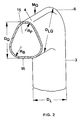
- the cross-tube section or sections has a substantially parabolic cross section with a straight or slightly curved base side which closes the parabolic opening, the respective base corners being rounded, and in that the cross-sectional area of the parabolic cross-section is approximately equal to the cross-sectional area of the longitudinal tube sections.
- Parabola is understood to mean a form that only approximately corresponds to a parabola, ie does not have to obey exactly a mathematical parabola equation.
- the glass wall thickness distribution is particularly advantageous if the ratio of the radius of curvature of the parabolic vertex (R P ) to the radius of curvature of the rounded base corners (R B ) is between 0.7 and 1.1, the ratio of the distance (D Q ) of the outer surface line (M Q ) from the inner wall of the U-tube opposite this in the cross tube sections and the diameter (D L ) in the longitudinal tube sections is between 0.8 and 1.3.
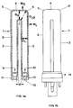
- the tubular discharge vessel or discharge tube 1 shown in Figure 1a consists of the two longitudinal tube sections 2, 3 and the cross tube section 4.
- the U-shaped bend of the discharge tube 1 is designed so that the outer surface line M Q of the cross tube section 4 is straight and substantially perpendicular to the outer surface lines M L of the two longitudinal tube sections 2, 3 runs.
- the outer diameter D L of the respective longitudinal tube sections 2, 3 is approximately 12 mm, the distance of the surface line M Q from the opposite glass outer wall or the diameter D Q of the cross tube section 4 in the middle thereof being selectable such that a ratio of D Q / D L is from about 0.8 to 1.3.
- the pipe transition between the longitudinal pipe sections 2, 3 and the cross pipe section 4 is such that the ratio of the diameter D LQ in the respective pipe bend to the diameter D Q can be approximately between 1.1 and 1.3. Furthermore, the ratio D LQ / D L is in the range from 1.05 to 1.5.
- the resulting cold spots in the outer tube bends 5, 6 ensure an optimal mercury vapor pressure of about 8 ⁇ 10 ⁇ 3 mbar during operation of the lamp.
- the inner tube bend 7 has an extremely small radius of curvature, so that the clear distance d between the two longitudinal tube sections 2, 3 is less than 5 mm, that is less than D L / 2.
- the inner surface of the tubular discharge vessel 1 is provided with a phosphor coating 8, which usually consists of a three-band phosphor. Electrode systems 9, 10 are melted at each of the two ends of the discharge vessel 1 by means of press seals 11, 12. One of the pipe ends is provided with a melted pump stem 13. As a filling, the discharge vessel contains 1 mercury in an amount of approx. 10 mg and 3 mbar argon as the ignition gas.
- FIG. 1b shows the mercury vapor low-pressure discharge lamp according to FIG. 1a with the base 14 mounted (not explained in further detail). At the inside the base 14 is still a glow starter with the appropriate interference suppression capacitor (not shown).
- the cross section of the cross tube section shown in FIG. 2 is parabolic in shape with a slightly curved base side 16 that closes the parabolic opening 15, the corners on the parabolic base 16 being rounded.
- the parabola vertex and the base curves have different radii of curvature R P or R B , but it is also possible to provide these curvatures with a uniform radius of curvature.
- the ratio of the radius of curvature R P of the parabola vertex to the radius of curvature R B of the rounded base corners is between 0.7 and 1.1.
- the diameter D LQ in the pipe bends 5, 6 is larger than the diameter D L of the longitudinal pipe sections 2 and 3 and on the other hand that the cross-sectional areas of the cross pipe section and the longitudinal pipe section are approximately the same size.
Landscapes
- Vessels And Coating Films For Discharge Lamps (AREA)
Applications Claiming Priority (2)
| Application Number | Priority Date | Filing Date | Title |
|---|---|---|---|
| DE9207139U DE9207139U1 (de) | 1992-05-26 | 1992-05-26 | Quecksilberdampf-Niederdruckentladungslampe |
| DE9207139U | 1992-05-26 |
Publications (2)
| Publication Number | Publication Date |
|---|---|
| EP0572835A1 true EP0572835A1 (fr) | 1993-12-08 |
| EP0572835B1 EP0572835B1 (fr) | 1996-12-04 |
Family
ID=6879914
Family Applications (1)
| Application Number | Title | Priority Date | Filing Date |
|---|---|---|---|
| EP93107843A Expired - Lifetime EP0572835B1 (fr) | 1992-05-26 | 1993-05-13 | Lamp à vapeur de mercure à basse pression |
Country Status (9)
| Country | Link |
|---|---|
| US (1) | US5635794A (fr) |
| EP (1) | EP0572835B1 (fr) |
| JP (1) | JP3363207B2 (fr) |
| KR (1) | KR100292455B1 (fr) |
| CN (1) | CN1059754C (fr) |
| CA (1) | CA2096905C (fr) |
| DE (2) | DE9207139U1 (fr) |
| HK (1) | HK1000610A1 (fr) |
| HU (1) | HU213968B (fr) |
Cited By (1)
| Publication number | Priority date | Publication date | Assignee | Title |
|---|---|---|---|---|
| EP0569814B1 (fr) * | 1992-05-13 | 1998-03-18 | Patent-Treuhand-Gesellschaft für elektrische Glühlampen mbH | Tube à décharge à basse pression |
Families Citing this family (13)
| Publication number | Priority date | Publication date | Assignee | Title |
|---|---|---|---|---|
| SE9300163L (sv) * | 1993-01-20 | 1994-07-21 | Lumalampan Ab | Kompaktlysrör |
| HU218642B (hu) * | 1996-12-30 | 2000-10-28 | General Electric Co | Egyoldalon fejelt kisülőlámpa |
| DE60043132D1 (de) * | 1999-05-19 | 2009-11-26 | Panasonic Corp | U-förmige Niederdruck-Quecksilberdampfentladungslampe und Herstellungsverfahren für eine solche Lampe |
| JP4206632B2 (ja) | 2000-10-31 | 2009-01-14 | 日本碍子株式会社 | 高圧放電灯用発光容器 |
| JP2002141020A (ja) * | 2000-10-31 | 2002-05-17 | Ngk Insulators Ltd | 高圧放電灯用発光容器 |
| JP4144176B2 (ja) | 2000-11-22 | 2008-09-03 | 日本碍子株式会社 | 高圧放電灯用発光容器 |
| JP4116808B2 (ja) * | 2001-11-14 | 2008-07-09 | 松下電器産業株式会社 | 電球形蛍光ランプ |
| ITVE20020003A1 (it) * | 2002-01-11 | 2003-07-11 | Primec S P A | "dispositivo di fissaggio della base dell'attacco dello scarpone ad uno snowboard".- |
| US6791272B2 (en) * | 2002-08-27 | 2004-09-14 | Lcd Lighting, Inc. | Fluorescent lamp providing uniform backlight illumination for displays |
| US7042147B2 (en) * | 2002-08-27 | 2006-05-09 | Lcd Lighting, Inc. | Serpentine fluorescent lamp with shaped corners providing uniform backlight illumination for displays |
| US6828720B2 (en) | 2002-12-18 | 2004-12-07 | Osram Sylvania Inc. | Compact fluorescent sun-tanning lamp |
| WO2006106645A1 (fr) * | 2005-04-01 | 2006-10-12 | Matsushita Electric Industrial Co., Ltd. | Procédé de fabrication de tube de verre à double hélice, tube luminescent pour lampe fluorescente et lampe fluorescente |
| JP2008084686A (ja) * | 2006-09-27 | 2008-04-10 | Toshiba Lighting & Technology Corp | 蛍光ランプおよび照明器具 |
Citations (4)
| Publication number | Priority date | Publication date | Assignee | Title |
|---|---|---|---|---|
| EP0061758A2 (fr) * | 1981-03-31 | 1982-10-06 | Patent-Treuhand-Gesellschaft für elektrische Glühlampen mbH | Lampe à vapeur de mercure à basse pression et méthode de fabrication |
| US4558400A (en) * | 1982-01-15 | 1985-12-10 | Johann Buser | Production of light from a fluorescent tube with reduction of the dazzling |
| EP0296534A2 (fr) * | 1987-06-22 | 1988-12-28 | Gte Products Corporation | Lampe à arc à décharge à basse pression à luminosité de surface élevée |
| WO1989009487A1 (fr) * | 1988-03-22 | 1989-10-05 | Lumalampan Aktiebolag | Tube fluorescent compact et son procede de fabrication |
Family Cites Families (7)
| Publication number | Priority date | Publication date | Assignee | Title |
|---|---|---|---|---|
| US4184480A (en) * | 1978-04-10 | 1980-01-22 | Corning Glass Works | Vacuum window for solar transmission |
| US4853591A (en) * | 1983-11-25 | 1989-08-01 | Patent Treuhand Gesellschaft Fur Elektrische Gluhlampen Mbh | Multiple-tube compact low-pressure discharge fluorescent lamp |
| JPS61240556A (ja) * | 1985-04-18 | 1986-10-25 | Mitsubishi Electric Corp | 小形螢光ランプ |
| JPH0746598B2 (ja) * | 1986-05-29 | 1995-05-17 | 東芝ライテック株式会社 | 蛍光ランプ |
| SE457760B (sv) * | 1987-03-23 | 1989-01-23 | Lumalampan Ab | Foerfarande foer framstaellning av kompaktlysroer |
| US5210963A (en) * | 1991-11-26 | 1993-05-18 | Harwood John M | Molded plastic toe cap |
| US5233262A (en) * | 1992-05-15 | 1993-08-03 | Judd B. Lynn | Flat form gas discharge lamp with optical reflecting means |
-
1992
- 1992-05-26 DE DE9207139U patent/DE9207139U1/de not_active Expired - Lifetime
-
1993
- 1993-05-13 EP EP93107843A patent/EP0572835B1/fr not_active Expired - Lifetime
- 1993-05-13 DE DE59304649T patent/DE59304649D1/de not_active Expired - Lifetime
- 1993-05-22 CN CN93106110A patent/CN1059754C/zh not_active Expired - Lifetime
- 1993-05-24 JP JP14551693A patent/JP3363207B2/ja not_active Expired - Lifetime
- 1993-05-25 CA CA002096905A patent/CA2096905C/fr not_active Expired - Lifetime
- 1993-05-25 HU HU9301533A patent/HU213968B/hu not_active IP Right Cessation
- 1993-05-26 KR KR1019930009139A patent/KR100292455B1/ko not_active Expired - Lifetime
-
1995
- 1995-05-31 US US08/454,621 patent/US5635794A/en not_active Expired - Lifetime
-
1997
- 1997-11-11 HK HK97102154A patent/HK1000610A1/xx not_active IP Right Cessation
Patent Citations (4)
| Publication number | Priority date | Publication date | Assignee | Title |
|---|---|---|---|---|
| EP0061758A2 (fr) * | 1981-03-31 | 1982-10-06 | Patent-Treuhand-Gesellschaft für elektrische Glühlampen mbH | Lampe à vapeur de mercure à basse pression et méthode de fabrication |
| US4558400A (en) * | 1982-01-15 | 1985-12-10 | Johann Buser | Production of light from a fluorescent tube with reduction of the dazzling |
| EP0296534A2 (fr) * | 1987-06-22 | 1988-12-28 | Gte Products Corporation | Lampe à arc à décharge à basse pression à luminosité de surface élevée |
| WO1989009487A1 (fr) * | 1988-03-22 | 1989-10-05 | Lumalampan Aktiebolag | Tube fluorescent compact et son procede de fabrication |
Cited By (1)
| Publication number | Priority date | Publication date | Assignee | Title |
|---|---|---|---|---|
| EP0569814B1 (fr) * | 1992-05-13 | 1998-03-18 | Patent-Treuhand-Gesellschaft für elektrische Glühlampen mbH | Tube à décharge à basse pression |
Also Published As
| Publication number | Publication date |
|---|---|
| CN1059754C (zh) | 2000-12-20 |
| EP0572835B1 (fr) | 1996-12-04 |
| JP3363207B2 (ja) | 2003-01-08 |
| CA2096905C (fr) | 2003-01-07 |
| HU213968B (en) | 1997-11-28 |
| CN1081021A (zh) | 1994-01-19 |
| DE59304649D1 (de) | 1997-01-16 |
| KR100292455B1 (ko) | 2001-09-17 |
| CA2096905A1 (fr) | 1993-11-27 |
| JPH0636743A (ja) | 1994-02-10 |
| KR930024081A (ko) | 1993-12-21 |
| DE9207139U1 (de) | 1992-07-16 |
| US5635794A (en) | 1997-06-03 |
| HU9301533D0 (en) | 1993-09-28 |
| HUT64159A (en) | 1993-11-29 |
| HK1000610A1 (en) | 1998-04-09 |
Similar Documents
| Publication | Publication Date | Title |
|---|---|---|
| EP0572835B1 (fr) | Lamp à vapeur de mercure à basse pression | |
| DE69501490T2 (de) | Dielektrikumbegrenzte Entladungslampe | |
| EP0061758B1 (fr) | Lampe à vapeur de mercure à basse pression et méthode de fabrication | |
| DE3716485C1 (de) | Xenon-Kurzbogen-Entladungslampe | |
| EP0439749B1 (fr) | Raccord vissé | |
| DE3431792C2 (de) | Faltenbalgvorrichtung | |
| EP0279159A1 (fr) | Corps métallique utilisé comme support de catalyseur constitué de deux couches différentes de tôle ondulée | |
| DE4133077C2 (de) | Kompakte Leuchtstofflampe | |
| DE68916199T2 (de) | Quecksilberdampf-Niederdruckentladungslampe. | |
| EP0453652B1 (fr) | Lampe à décharge à haute pression | |
| DE10353861B4 (de) | Entladungslampe vom Kurzbogentyp | |
| DE19548305C2 (de) | Gasentladungsgefäß für Gasentladungslampen | |
| DE3320919C2 (fr) | ||
| DE20106002U1 (de) | Metallhalogenidlampe mit keramischem Entladungsgefäß | |
| EP0569814B1 (fr) | Tube à décharge à basse pression | |
| DE69825035T2 (de) | Hochdruck-Entladungslampe | |
| EP0246548A1 (fr) | Procédé pour la fabrication d'un réservoir à décharge pour lampes compactes à décharge à basse pression | |
| EP0219860B1 (fr) | Méthode de fabrication d'une lampe à décharge à haute pression à halogénures de métal à pincement unique et une lampe fabriquée suivant cette méthode | |
| EP1351278B1 (fr) | Lampe à halogénure métallique avec enveloppe céramique | |
| DE9015090U1 (de) | Sammler für einen Flachrohrverflüssiger | |
| EP0250920B1 (fr) | Lampe à décharge à haute pression à halogénure métallique | |
| DE2352929C3 (de) | Mehrfachfalzverbindung | |
| DE202005008112U1 (de) | Gestell für eine Entladungslampe | |
| DE19647832A1 (de) | Eine Kompakt-Leuchtstofflampe und ein Verfahren zur Herstellung derselben | |
| DE19653364C2 (de) | Blitzröhre |
Legal Events
| Date | Code | Title | Description |
|---|---|---|---|
| PUAI | Public reference made under article 153(3) epc to a published international application that has entered the european phase |
Free format text: ORIGINAL CODE: 0009012 |
|
| AK | Designated contracting states |
Kind code of ref document: A1 Designated state(s): DE FR GB IT SE |
|
| 17P | Request for examination filed |
Effective date: 19940110 |
|
| 17Q | First examination report despatched |
Effective date: 19950320 |
|
| GRAG | Despatch of communication of intention to grant |
Free format text: ORIGINAL CODE: EPIDOS AGRA |
|
| GRAH | Despatch of communication of intention to grant a patent |
Free format text: ORIGINAL CODE: EPIDOS IGRA |
|
| GRAH | Despatch of communication of intention to grant a patent |
Free format text: ORIGINAL CODE: EPIDOS IGRA |
|
| GRAA | (expected) grant |
Free format text: ORIGINAL CODE: 0009210 |
|
| AK | Designated contracting states |
Kind code of ref document: B1 Designated state(s): DE FR GB IT SE |
|
| REF | Corresponds to: |
Ref document number: 59304649 Country of ref document: DE Date of ref document: 19970116 |
|
| ET | Fr: translation filed | ||
| ITF | It: translation for a ep patent filed | ||
| GBT | Gb: translation of ep patent filed (gb section 77(6)(a)/1977) |
Effective date: 19970206 |
|
| PLBE | No opposition filed within time limit |
Free format text: ORIGINAL CODE: 0009261 |
|
| 26N | No opposition filed | ||
| REG | Reference to a national code |
Ref country code: GB Ref legal event code: IF02 |
|
| PGFP | Annual fee paid to national office [announced via postgrant information from national office to epo] |
Ref country code: GB Payment date: 20060505 Year of fee payment: 14 |
|
| PGFP | Annual fee paid to national office [announced via postgrant information from national office to epo] |
Ref country code: FR Payment date: 20060523 Year of fee payment: 14 |
|
| PGFP | Annual fee paid to national office [announced via postgrant information from national office to epo] |
Ref country code: IT Payment date: 20060531 Year of fee payment: 14 |
|
| GBPC | Gb: european patent ceased through non-payment of renewal fee |
Effective date: 20070513 |
|
| REG | Reference to a national code |
Ref country code: FR Ref legal event code: ST Effective date: 20080131 |
|
| PG25 | Lapsed in a contracting state [announced via postgrant information from national office to epo] |
Ref country code: GB Free format text: LAPSE BECAUSE OF NON-PAYMENT OF DUE FEES Effective date: 20070513 |
|
| PG25 | Lapsed in a contracting state [announced via postgrant information from national office to epo] |
Ref country code: FR Free format text: LAPSE BECAUSE OF NON-PAYMENT OF DUE FEES Effective date: 20070531 |
|
| PG25 | Lapsed in a contracting state [announced via postgrant information from national office to epo] |
Ref country code: IT Free format text: LAPSE BECAUSE OF NON-PAYMENT OF DUE FEES Effective date: 20070513 |
|
| REG | Reference to a national code |
Ref country code: DE Ref legal event code: R081 Ref document number: 59304649 Country of ref document: DE Owner name: OSRAM GMBH, DE Free format text: FORMER OWNER: OSRAM GESELLSCHAFT MIT BESCHRAENKTER HAFTUNG, 81543 MUENCHEN, DE Effective date: 20111130 |
|
| PGFP | Annual fee paid to national office [announced via postgrant information from national office to epo] |
Ref country code: SE Payment date: 20120507 Year of fee payment: 20 |
|
| PGFP | Annual fee paid to national office [announced via postgrant information from national office to epo] |
Ref country code: DE Payment date: 20120720 Year of fee payment: 20 |
|
| REG | Reference to a national code |
Ref country code: DE Ref legal event code: R081 Ref document number: 59304649 Country of ref document: DE Owner name: OSRAM GMBH, DE Free format text: FORMER OWNER: OSRAM AG, 81543 MUENCHEN, DE Effective date: 20130205 |
|
| REG | Reference to a national code |
Ref country code: DE Ref legal event code: R071 Ref document number: 59304649 Country of ref document: DE |
|
| PG25 | Lapsed in a contracting state [announced via postgrant information from national office to epo] |
Ref country code: DE Free format text: LAPSE BECAUSE OF EXPIRATION OF PROTECTION Effective date: 20130514 |