EP0572853B1 - Swimming flipper - Google Patents
Swimming flipper Download PDFInfo
- Publication number
- EP0572853B1 EP0572853B1 EP93107986A EP93107986A EP0572853B1 EP 0572853 B1 EP0572853 B1 EP 0572853B1 EP 93107986 A EP93107986 A EP 93107986A EP 93107986 A EP93107986 A EP 93107986A EP 0572853 B1 EP0572853 B1 EP 0572853B1
- Authority
- EP
- European Patent Office
- Prior art keywords
- blade
- shoe
- locking member
- heel
- flipper according
- Prior art date
- Legal status (The legal status is an assumption and is not a legal conclusion. Google has not performed a legal analysis and makes no representation as to the accuracy of the status listed.)
- Expired - Lifetime
Links
Images


Classifications
-
- A—HUMAN NECESSITIES
- A63—SPORTS; GAMES; AMUSEMENTS
- A63B—APPARATUS FOR PHYSICAL TRAINING, GYMNASTICS, SWIMMING, CLIMBING, OR FENCING; BALL GAMES; TRAINING EQUIPMENT
- A63B31/00—Swimming aids
- A63B31/08—Swim fins, flippers or other swimming aids held by, or attachable to, the hands, arms, feet or legs
- A63B31/10—Swim fins, flippers or other swimming aids held by, or attachable to, the hands, arms, feet or legs held by, or attachable to, the hands or feet
- A63B31/11—Swim fins, flippers or other swimming aids held by, or attachable to, the hands, arms, feet or legs held by, or attachable to, the hands or feet attachable only to the feet
- A63B2031/112—Swim fins, flippers or other swimming aids held by, or attachable to, the hands, arms, feet or legs held by, or attachable to, the hands or feet attachable only to the feet with means facilitating walking, e.g. rectractable, detachable or pivotable blades
Definitions
- the present invention is related to swimming flippers comprising a blade of flexible and relatively rigid material, and a shoe of relatively soft and elastically extensible material associated to one end of the blade.
- the shoe In the swimming flippers presently produced the shoe, be it either formed with a complete shape or open rearwardly and provided with a strap (for the rear holding of the foot and for the length adjustment of the housing thereof), is rigid with the blade, or in any case is permanently assembled thereto by means of mechanical systems allowing assembly and disassembly of the two parts only with the aid of suitable tools, and in any case not when the shoe is worn on the user's foot.
- the manufacture technology has by now consolidated, comprising initially the injection moulding of the blade, employing a rigid and flexible thermoplastic material having a low melting point, normally E.V.A. (Ethylene Vinyl Acetate) or rigid polyurethane or other polymers. Thereafter, on the rear end of the blade so formed the shoe is overmoulded, for which it is normally employed a thermoplastic rubber having chemical affinity with the thermoplastic material of the blade and a higher melting temperature, so that it can be welded to the blade due to a chemical-thermal effect.
- a rigid and flexible thermoplastic material having a low melting point normally E.V.A. (Ethylene Vinyl Acetate) or rigid polyurethane or other polymers.
- a technology more frequently adopted for specialized uses of the flipper consists of a moulded shoe of generally natural rubber, sometimes a thermoplastic rubber, and a blade of rigid and flexible material coupled and fixed therebetween by means of mechanical systems, normally by screws.
- This type of connection which can be disconnected only with the aid of proper tools, also leeds to flippers which, both from the point of view of the user and during operation, must be considered as "monolithic", even if uncoupling of the two parts is allowed for the purpose of replacement.
- GB-A-2.128.096 discloses a swimmimg flipper comprising a platform for fixing the flipper blade to a conventional shoe, wherein the disengageable coupling means may comprise screws passing through the sole of the shoe and the platform of the blade, or (for instance in the embodiment disclosed in the British specification with reference to Figure 9A) rearward lock means performing quick engagement of the heel of the shoe following approach of the shoe and the blade relative to each other in a direction substantially perpendicular to the plane of the blade.
- Binding between the front portion of the shoe and the platform of the flipper blade is accomplished in the first case also by screws, and in the second case by means of a Velcro strap encircling the shoe as well as the platform. In either case, manual intervention of the user at least for closing the strap (or tightening the screws) is strictly necessary.
- the front end of the shoe is not rigidly secured to the blade, even in the tightened condition of the Velcro strap, owing to flexibility or stretching thereof.
- the connection is slack and in any case not sufficiently rigid for efficient transmission of the swimming power to the blade.
- loose attachment of the front end of the shoe may also negatively affect the binding of the rear end thereof and is thus unsafe, in consideration of the risk for the user of accidental disengagement of the flipper.
- the object of the present invention is to overcome the above mentioned drawbacks both of the so called monolithic flippers, and of the flippers formed by two parts coupled to each other such as previously disclosed, and to provide a swimming flipper wherein the blade an the shoe are constituted by two distinct elements adapted to be separated from each other and provided with means of mutual restrained-joint coupling enabling separation and putting together the blade and the shoe in a simple and rapid way, also when the shoe is worn on the user's foot.
- a further object of the invention is to allow coupling between the shoe and the blade automatically, without any need of manual intervention, by means of a single "step in” operation.
- Still another object of the invention is to enable the separation between the shoe and the blade with only one hand and with a minimum effort, also through a single operation.
- Still a further object of the invention is to provide an amphibious footwear, which allows both walking in the same way and even better than it is made possible by the current isothermal ankle-boots, and swimming in the same way and even better than the prior art flippers permit, and changing from one condition to the other - walking/swimming and viceversa - by easy, rapid and instinctive actions adapted to be carried out even in a complete diver's configuration, possibly even with his isothermal boots already worn.
- a further object of the invention is to let the shoe allow - besides the possible isothermal protection due to the use of an insulating material such as foamed cellular neoprene - a comfortable and easy walking, by virtue of a semi-rigid anti-slip sole, well secured to the shoe, possibly by means of straps adapted to be tightened in an adjustable way with hook-and-loop fasteners or the like.
- an insulating material such as foamed cellular neoprene - a comfortable and easy walking, by virtue of a semi-rigid anti-slip sole, well secured to the shoe, possibly by means of straps adapted to be tightened in an adjustable way with hook-and-loop fasteners or the like.
- a further object of the invention is to enable the blade to be connected or disconnected relative to the shoe either when the shoe is not worn on the user's foot, or, particularly, when the user is already wearing the shoe.
- Still another object of the invention is to avoid chemically-obliged selections for the material of the blade and that of the shoe, as it is instead required in the case of flippers formed by different materials adapted to be welded to each other by co-moulding.
- a further object of the invention is to provide, in the coupled condition between the blade and the shoe, a joint between the foot and the blade which is rigid and without yielding or plays, for the best transmission of the swimming effort from the foot to the blade.
- a further object of the invention is to provide a connection between the shoe and the blade which is constructively simple, compact and substantially devoid of parts which may induce hydrodynamic resistance effects.
- a further object of the invention is to provide a connection between the shoe and the blade which is adapted to ensure a high degree of safety against risks of undesired disengagement in use.
- the said coupling means further comprise forward instep means cooperating with said rearward snap-lock means so as to perform fully automatic rigid snap-fit engagement of the shoe relative to the blade without any need of manual intervention.
- the term "direction substantially perpendicular to the plane of the blade” is intended to designate both a translation movement, for instance from above downwards of the shoe towards the blade placed on a support surface, and a composite translation-rotation movement, with an initial phase of translation of the tip or of the heel of the shoe until resting on the blade, followed by a final rotation phase of the shoe so as to bring also the heel or, respectively, the tip to lay onto the blade.
- shoe it is to be intended an assembly formed by a rubber-like portion (foamed neoprene, elastic thermal insulating material), having a low configuration (i.e. shaped as a normal shoe) or having a tall configuration (i.e. shaped as an ankle-boot), and by an anti-slip sole, the said assembly being conveniently equipped with slide-fasteners, straps or hook-and-loop fasteners or the like, ensuring both easy wearing and the possibility of tightening and improving foot restraint.
- the said means for the mutual restrained joint between the shoe and the blade comprise conveniently a substantially rigid sole, and preferably having a unidirectional flexibility (such as to allow flexion and bending of the tip portion of the shoe upwardly, for enabling a normal deambulation, but not downwardly to avoid negative effects on operation during swimming) associated to the shoe and having a tip projection at the forward end thereof and a heel portion, and a rigid holding toe and a heel locking member associated to the blade and cooperating with the tip projection and with the heel portion of the said sole, respectively.
- a unidirectional flexibility such as to allow flexion and bending of the tip portion of the shoe upwardly, for enabling a normal deambulation, but not downwardly to avoid negative effects on operation during swimming
- the heel portion of the shoe is provided with a hooking-tooth back appendage and the heel locking member carried by the blade comprises an elastically deformable wing projecting in a direction substantially perpendicular to the blade and having a recess therein adapted to be snap-engaged by the said hooking tooth.
- the hooking tooth and the elastically deformable wing are conveniently formed with respective skid surfaces adapted to slidingly cooperate with each other during approaching of the shoe and the blade relative to each other so as to allow snap-fitting of the said hooking tooth within the recess of the said wing.
- the holding toe and/or the heel locking member can be advantageously fixed to the blade in an adjustable way, so as to allow the use of the flipper with shoes of different sizes, or use of different blades on the same shoe.
- Safety means are conveniently further provided for preventing accidental disengament between the shoe and the blade during use of the flipper.
- the holding toe and/or the heel locking member can be formed by distinct members mechanically fixed to the blade, or carried by a plate in turn fixed to the blade, or can be integral or co-moulded with the blade.
- the invention contemplates two alternative embodiments: the first consists of providing a special boot, having the sole incorporated therewith, and the second consists of employing a normal boot available on the market with the addition of an overshoe incorporating the sole.
- the sole of the shoe can be directly integrated therewith by glueing, overmoulding, sewing or other equivalent systems, or can be constituted by a plantar ("sandal" or “overshoe") having preferably a unidirectional flexibility, distinct from the shoe and connected thereto in a releasable way.
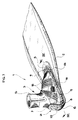
- a swimming flipper 1 essentially comprises a blade 2 and a shoe 3 constituted by two distinct elements which can be separated from each other and coupled to each other in a rigid way.
- the blade 2 is constituted a plate of relatively rigid and flexible plastic material, possibly having a multi-layer structure according to the teachings of European patent application EP-A-0436927 in the name of the same Applicant.
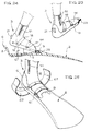
- the blade 2 has a rear tapered end 4 in correspondence of which a plate 5 is applied, normally made by metal or plastic material, which can be defined as a "binding" on the analogy of systems employed in other technical fields (for instance in the field of skying) for fastening a shoe to a member adapted to be used fixedly with the shoe itself.
- the plate 5 can be welded, glued or fixed by any equivalent system to the blade 2, or it can be integrated by moulding or even formed in one piece with the blade itself, by means of a localised thickening of the central area of the tapered end 4.
- the rear end of the plate 5 is formed with a wing 6 bent substantially perpendicularly to the plane of the blade 2 and having a terminal portion 7 slightly arcuated in a direction opposed to the said blade. Below the terminal portion 7, the wing 6 is formed with an opening 8 the function of which will be clarified in the following.
- the wing 6 is elastically deformable, i.e. Is able to spring relative to the plate 5, and defines a heel locking member cooperating, in the way which be clarified in the following, with the shoe 3.
- a holding toe 9 is placed in proximity to the end of the plate 5 opposed to the heel locking member 6, having a mounting portion 10 fixed to the plate 5 or directly to the blade 2, and defining a holding receptacle 11 also intended to cooperate, as explained hereinafter, with the shoe 3.
- the receptacle 11 can be shaped as a closed recess, such as shown in the example of figures 1 through 4, or it can be formed with different shapes, which will be disclosed in the following.
- fixing between the mounting portion 10 of the holding toe 9 and the plate 5 is made in an adjustable way, so as to allow variation of the distance thereof relative to the heel locking member 6, by means of screws 12 adapted to be engaged within a plurality of threaded holes 13 of the plate 5.
- the holding toe 9 can even be permanently fixed to the plate 5, and even be formed in one piece therewith, such as explained in the following.
- a thrust elastic member is disposed which, in the case of the shown example, is constituted by a spring tab 14 projecting, relative to the plane of the blade 2, on the same side of the heel locking member 6.
- This thrust elastic member is not a strictly necessary element, and in any case it could be replaced by equivalent elements adapted to perform the same function, such as for example a metal or plastic material spring having a different shape, or an elastic shim made of rubber, suitably positioned.
- the shoe 3 comprises, in the case of the shown example, an ankle-boot 15 of soft material, for instance of elastomeric material or the like (according to the most common technology, foamed cellular neoprene lined by an anti-tearing fabric), having a sole 16 which is substantially rigid or anyway preferably provided with a unidirectional flexibility for facilitating walking.
- an ankle-boot 15 of soft material for instance of elastomeric material or the like (according to the most common technology, foamed cellular neoprene lined by an anti-tearing fabric)
- a sole 16 which is substantially rigid or anyway preferably provided with a unidirectional flexibility for facilitating walking.
- the sole 16 should preferably be provided with the following features:
- the sole 16 can preferably be made as an integrant part of the shoe 3, such as disclosed hereinafter, or alternatively, as in the case of the shown example, it can be formed by a distinct plantar which is part of an overshoe 17 detachably connected to the ankle-boot 15, for instance by means of top straps 18 with hook-and-loop fasteners, buckles or equivalent system. These fasteners must be able to facilitate wearing and adjustment, according to the user's demands, tightening of the overshoe 17 on the foot, enabling both a comfortable deambulation and a powerful force transmission during swimming.
- top tightening straps can even be used when the sole 16 is directly integrated with the shoe 3, since they can perform the tasks of adjustment and of rendering fixed the dynamic coupling foot/blade. With a tightened adjustment of the straps, the foot can transmit the power to the blade with immediateness, precision and high efficiency, without useless hysteresis.
- overshoe 17 is directly worn on the bare foot, or on the foot simply protected by a isothermal sock.
- the overshoe 17 can be made of relatively rigid plastic material, and the sole 16 has a thickened cross section with longitudinal inner reinforcement and stiffening elements 19. Possibly, the sole can also be partially or totally covered by anti-slipping rubber.
- the heel portion of the overshoe 17, indicated as 20, is formed with a hooking tooth 21 projecting outwardly and placed at a level corresponding to that of the opening 8 of the heel locking member 6.
- the hooking tooth 21 has a lower skid surface 22 whose shape is complementary to that of the bent terminal portion 7 of the heel locking member 6.
- the sole 16 is formed with a tip projection 23 whose shape is complementary to that of the receptacle 11 of the holding toe 9.
- the user preliminarly wears the shoe 3 and then the overshoe 17, and is thus able to walk freely and without any difficulty until the time of real need of employing the flipper, possibly maintaining a loose adjustment of the tightening straps 18 for a better comfort.
- the blade 2 is simply laid onto a support surface (shore, edge of a swimming pool, deck of a boat) even standing up without the need of bending down or using hands, with the heel locking member 6 facing upwardly.
- the user approaches the shoe 3 to the plate 5, firstly introducing the tip projection 23 within the receptacle 11 of the holding toe 9. Subsequently, by simply lowering the heel towards the plate 5, snap-fitting between the hooking tooth 21 and the opening 8 of the heel locking member 6 is performed, thus rigidly locking the shoe 3 relative to the blade 2.
- the snap fitting between the tooth 21 and the opening 8 is obtained by virtue of the elastic bending rearwardly of the heel locking member 6, carried out owing to the sliding contact between the skid surface 22 of the tooth 21 and the terminal bent portion 7 of the heel locking member 6.
- the elastic tab 14 of the plate 5 is elastically deformed downwardly, thus applying onto the sole 16 a thrust directed upwardly, which ensures a firm and free of play restraint of the hooking tooth 21 against the upper edge of the opening 8.
- the tab 14 constitutes a security member against risks of accidental or anyway undesired disengagement of the shoe 3 relative to the blade 2.
- the function of the elastic tab 14, which in any case is not strictly necessary, can also be performed by a metal or plastic material spring, or by an elastically compressible rubber shim, or by similar systems.
- seats or notches 21a can be formed on the upper side of the tooth 21, and even flexible hooking appendages can be provided (such as it will be clarified in the following), adapted to engage and retain the upper edge of the opening 8.
- the flipper according to the invention enables coupling and uncoupling between the shoe 3 and the blade 2 in an extremely comfortable, practical and simple way. Coupling can be performed automatically, without the need of any manual intervention, while uncoupling requires in any case a minimum effort, intervening with only one user's hand or of a suitable tool, or by means of the sole of the other foot.
- connection between the shoe 3 and the blade 2 is absolutely rigid, which ensures the best transmission of the swimming force to the blade 2, and thus the maximum thrust efficiency by the latter.
- fastening straps 18 ensure a solid connection between the user's foot and the shoe 3.
- the holding toe 9 and the heel locking member 6 could have different shapes with respect to those disclosed with reference to the above example, provided that same can afford a rapid automatic snap-fit engagement of the shoe 3 relative to the blade 2 following a mutual approaching therebetween along a direction substantially perpendicular to the plane of the blade 2, such as clarified at the beginning, i.e. following a translation movement from above downwardly, or following a composite movement of translation-rotation.
- Figure 5 shows an alternative embodiment in which the plate 5 is suppressed (i.e. is integral with the blade 2), the holding toe 9 is co-moulded with the blade 2, and the heel locking member 6 is adapted to be fixed on the rear portion 4 of the blade 2 in an adjustable way.
- the portion 4 is provided with a profiled central groove 25 directed longitudinally and adapted to be engaged by a projection 26 fixed to the lower face of the plate 5.
- the plate 5 is fixed by means of the screws 13 which cross the rear portion 4 and engage a lower counterplate 27.
- Figure 6 shows an alternative embodiment according to which the sole 16 is directly integrated with the shoe 3.
- the shoe is formed by a boot 28 for instance made by foamed neoprene, glued onto the sole 16 of substantially rigid material and having a unidirectional flexibility, and a layer of rubber 29 is overmoulded on the sole 16 so as to ensure both anti-slippling characteristics and glueing with the boot 28.
- the safety system for preventing accidental or anyway undesired disengagement of the shoe 3 relative to the blade 2 can also be made according to the alternative embodiments depicted in figures 7, 8 and 9.
- the heel locking member 6 is formed with an upper hook-bent end 30 and the hooking tooth 21 of the shoe 3 is replaced by a hollow projection 32 adapted to be crossed by the heel locking member 6 and engaged from above by the hool end 30.
- the heel locking member 6 is formed with two vertical branches 32 which can be elastically drawn near to each other and having at their ends respective hooking teeth 33 intended to pass through the hollow projection 31 and to engage thereabove.
- a further safety system is shown in figure 12: it comprises a spring pawl 34 supported in correspondence of the upper end of the hooking tooth 21 and adapted to be automatically rotated downwardly, against the action of the spring, when the hooking tooth 21 is introduced through the opening 8 of the heel locking member 6. In order to disengage the tooth 21 from the opening 8 it is then necessary to manually push downwardly the pawl 34 so as to disengage same from the upper edge of the opening 8.
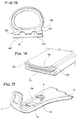
- Figures 10 and 11 show different configurations of the holding toe associated to the blade for the restraint of the front portion of the shoe 3: in the first case it is simply provided a transverse bridge-shaped band 9a, which can be formed in one piece by moulding with the blade 2, while in the second case a pocket 9b, possibly flexible and/or soft, is provided. In both cases the need of the rigid tip element 23 of the sole 16 is suppressed.
- Figure 13 shows an embodiment wherein the coupling between the shoe 3 and the blade 2 can be obtained by a simple translation movement from above downwardly of the user's foot.
- the heel locking member 6 is limited to a simple rear wall 37
- the sole 16 is provided with a heel 36 having an undercut recess 38 intended to be engaged by a spring latch 34 slidable on the plate 5 in the longitudinal direction thereof.
- the holding toe is also constituted by a spring latch 35, adapted to engage the tip portion 23 of the sole 16.
- a positioning wedge 29, preferably conical, is formed on the plate 5 for guiding the sole 16 into the correct locking position, preventing translations of the shoe 3 on the horizontal plane.
- the latches 34 and 35 could also be constituted by mechanically equivalent systems, possibly even provided with elastic or of different type safety members, intended to be only voluntarily disengaged by the user.
- Figures 14, 15 and 16 show provision of positioning members formed by prismatic or fusto-pyramidal projections 40, or by male and female ribs 41, 42, or simply by lateral walls 43 for a form coupling between the sole 16 and the blade 2, in such a way that, during coupling operation, the shoe 3 can be guided towards the correct engagement position and, after engagement by the heel locking member 6, locked in position so as to prevent translations thereof along directions parallel to the blade plane.
- FIG. 18 A further safety system for preventing accidental or undesired disengagement of the shoe 3 relative to the blade 2 is shown in figures 18 and 19.
- This system comprises a substantially fork-shaped body 50, slidably mounted on the upper end 7 of the heel locking member 6 and whose rear branch, having a longer dimension, defines a latch 45 adapted to engage from above the seat or notch 21a formed in the upper portion of the hooking tooth 21.
- the body 50, and thus the latch 45 are normally urged downwardly into the operative position shown in the drawings, under the action of a thrust spring 46 housed within an aperture 48 formed in the heel locking member 6 above the opening 8.
- This spring 46 reacts superiorly against the upper edge of the aperture 48 and lowerly against a transverse element 49, for instance a screw, carried by the body 50 and extending through the aperture 48.
- the screw 49 also performs the task of securing the body 50 relative to the heel locking member 6.
- the body 50 is provided superiorly with a grip portion 47 acting as a manoeuvre handle.
- the latter can be provided with suitable projections or even with a string or web so as to make the operation still more convenient.
- one end of the string partially indicated as 90, is be connected to the body 50, and the other end can either be free, or positioned with hook-end-loop fastener inserts or equivalent systems on the neoprene of the boot, and even secured to the user's diving suit.
- the string 90 can be made by a fluorescent material, adapted to be easily localised even under water.
- the latch 45 could be made so that disengagement thereof can be actuated, instead of pulling same upwardly, by means of a thrust from above downwardly and thus following lowering thereof. This allows disengagement of the shoe from the blade without any need of a manual intervention, but simply intervening with the user's heels, which is particularly convenient in the case of a completely dressed, and thus humpered, diver.
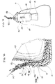
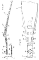
- Figures 20 through 22 show a preferred embodiment of the shoe 3 and sole 16 thereof.
- the shoe 3 is formed by a foamed cellular neoprene boot 15, both innerly and outerly covered by an anti-tearing fabric and having a lateral slide fastener 51 for facilitating wearing thereof and one or more reinforcing patches 52.
- the sole 16, which is also in this case permanently connected to the boot 15, is formed by a rigid but relatively flexible material, for instance thermoplastic polyurethane similar to the material adopted for ski-boot bodies, or flexible polyamide, or hard rubber.
- the shoe 16 is formed in the front area with the tip projection 23 protruding forwardly, and in the heel area with a wall 53 shaped same as the heel portion of the boot 15 and from which the hooking tooth 21 projects rearwardly. Actually the latter is detachably secured by means of a restrained joint to a support member 54 protruding in one piece from the back of the wall 53.
- This construction enables manufacturing of the hooking tooth 21 (shown in better detail in figure 22) by the most suitable material (rigid, anti-wear, anti-abrasion and anti-shock) for instance an acetalic resin or similar thermopolymers. Moreover, this conformation allows quick and easy replacement of the hooking tooth 21, if necessary.
- the upper face of the sole 16, indicated as 55, is flat and is rigidly fixed, normally by glueing, to a corresponding lower flat wall 56 of the boot 15.
- the lower face of the sole 16, shown in detail in figure 21, is provided with anti-skid material plates or projections 57, for instance of curable or thermoplastic rubber, soft polyurethane or the like, as well as with recesses or ribs 58 for the positioning thereof relative to the blade 2.
- the sole 16 has two lateral walls 59 with respective projections 60 for the connection, by means of rivets 61, of two adjustable straps 62.
- the two lateral walls 59 stiffen the sole 16 in connection with bending rigidity, and are formed in the front portion thereof with respective V-shaped slits 63 adapted to allow bending upwardly of the tip portion of the shoe 3 so as to make deambulation still more comfortable.
- a protection covering 64 is further provided for covering the tip portion of the shoe 3, which can be formed in one piece with the sole 16 or can be formed by a separate piece, for instance made by a more soft polyurethane material, welded to the front portion of the sole 16 after assembling thereof with the boot 15.
- Rigid connection between the boot 15 and the sole 16 can be obtained, besides glueing, with other technologies, such as for instance by compression under press, adhesion by overmoulding, or by means of injection of a binding material between the two parts.
- the hooking tooth 21 is formed according to this embodiment with a slidable coupling member 65 for its connection to the support 54, to which the tooth 21 is then fixed by means of screws 66. Like in the other previously disclosed embodiments, the hooking tooth 21 has a back arcuated skid surface 22. Additionally, it is provided superiorly with a flexible safety tab 66, whose function is to prevent (as it will be clarified in the following) accidental or undesired disengagement from the heel locking member 6 in the coupled condition between the shoe 3 and the blade 2.
- the hooking tooth 21 can be designed with different shapes, both in the case same is made in one piece with the sole 16 and the case it is constituted by a distinct element which can be separated from the sole 16. Same applies to the safety system against undesired disengagement: the only fundamental required features thereof consist of a rear vertical-oblique skidding surface, so as to facilitate the engagement operation between the shoe 3 and the blade 2, and a generally horizontal upper surface for restraint during swimming.
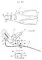
- Figures 23 through 25 diagrammatically show the "step-in” coupling phases between the shoe 3 and the blade 2 generally according to the embodiments disclosed in the above, wherein coupling is accomplished by a composite translation-rotation motion of the shoe 3, firstly bringing the tip portion of the shoe 3 into contact on the blade 2 and then rotating the heel portion thereof downwardly.
- the initial operation (figure 23) consists of wearing the shoe 3 on the user's foot and locking, and if necessary tightening, the two straps 18. In this condition deambulation is possible.
- an optional additional holding system is contemplated, constituted for instance by an auxiliary open strap shown as 67 in figure 25, whose ends are provided with buckle or hook-and-loop fasteners.
- the strap 67 is permanently secured to the area of the blade 2 beneath the user's foot, and is intended to be closed onto the foot after the coupling operation between the shoe 3 and the blade 2.
- the safety strap 67 can also perform the auxiliary task of further preventing bending of the tip portion of the sole 16 during swimming, thus avoiding any risks of accidental disengagement of the tip projection 23 from the holding toe 9.
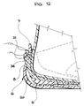
- FIGS 26 through 28 show a preferred embodiment of the blade 2 and of the heel locking member 6, which is particularly adapted for use with the shoe 3 according to figures 20 through 22.
- the heel locking member 6 proper is formed by an element distinct from the blade 2 and applied to a rear tapered end 68 thereof.
- the blade 2 is constituted by a hydrodynamic thrust body, designed with the usual blade shapes of conventional flippers, and incorporates within the rear end 68 thereof and insert 69, which is formed by separate moulding with a rigid, less flexible, more resistant and anti-shock plastic material (polypropylene, polycarbonate, nylon, acetalic resin), and subsequently incorporated within the blade 2 by co-moulding.
- the insert 69 is placed in the mould of the blade 2 and embedded within the mass material thereof, normally E.V.A., polyurethane, PVC or any other material adapted for flipper blades.
- the insert 69 which is substantially flat in the area corresponding to the foot sole of the user, defines the holding toe 9 intended to receive therein the tip projection 23 of the shoe 3.
- Such insert 69 is further provided with a through opening 70 placed beneath the holding toe 9 for allowing rotation of the tip projection 23 during coupling/uncoupling of the shoe 3 relative to the blade 2, and moreover is preferably formed with a front appendage 71, protrudring in front of the holding toe 9 and whose function is to more efficiently transmit the swimming power to the blade 2.
- the insert 69 is further formed with one or, as in the case of the shown example, two openings 72, placed rear to the holding toe 9 and intended for connection of the heel locking member 6. Rear to the openings 62, the insert 69 is formed with two sets of through holes 73 also for use in the connection of the heel locking member 6.
- the heel locking member 6 is made by a flexible material, since whenever the shoe 3 is engaged and disengaged relative thereto, it must elastically bend so as to allow rearward rotation of the wing 7 with the opening 8 for the hooking tooth 21 of the shoe 3.
- a substantially flat portion 74 which is placed below the terminal portion of the rear end 68 of the blade 2, and terminates at the end opposite to the wing 7 with a raised double nose 75 engaging the insert 69, through the openings 72 thereof.
- the central flat portion 74 has pairs of holes 76 theretrough, corresponding to the holes 73 and by which the heel locking member 6 can be adjustably secured to the blade 2, by means of screws 77.
- the heel locking member 6 and the rear end 68 of the blade 2 can be provided with respective male and female centering elements (not shown).
- the same blade 2 and the same heel locking member 6 can be used with shoes 3 of different sizes, simply varying the position between the holes 73 and the holes 76 relative to one another.
- This allows a considerable saving both of investments for moulds, and for storehouse stocks, with advantages also for the user.
- a diving club shall have a reduced flipper stock-yard and simply adjust the position of the heel locking members of each pair of flippers upon rental to the user members.
- a further advantage of this construction resides in that, forming the blade 2 and the heel locking member 6 as separate elements, it is possible to employ for each of them the most suitable material: in particular, a softer and less expensive material for the blade 2 (having larger dimensions), and a more expensive and high-performance material for the heel locking member 6 (having smaller dimensions).
- the heel locking member 6 can be provided inferiorly with anti-skid rubber projections, for instance constituted one by two or more transverse rubber members 78 crossing the central portion 74 and the heads of which are locked between the heel locking member 6 and the rear end 68 of the blade 2, after tightening of the screws 77.
- the rubber members 78 can be fixed by glueing or welding beneath the heel locking member 6 or even onto other selected areas of the blade 2.
- the insert 69 of figures 26 through 28 is suppressed, and is in practice replaced by the rear end 68 itself of the blade 2 which extends forwardly for the entire length and width of the flipper, so as to constitute the blade 2 or at least the bearing structure thereof.
- Figure 31 shows the coupled configuration between the shoe 3 according to the preferred embodiment of figures 20 through 22 and the blade 2 and heel locking member 6 according to the preferred embodiment of figures 26 through 28, with the only difference that the wing 7 of the heel locking member 6 is formed superiorly with a double wall, i.e. with an outer wall 80 enclosing posteriorly the opening 8 and defining in the upper portion of the heel locking member 6 an interspace 81 in which a release member 82 is slidably mounted for unlocking of the hooking tooth 21.
- the release member 82 can be formed by a rod or stem adapted to be operated from above and whose withdrawal from the interspace 81 is prevented by a lower projection 83.
- the release member 82 cooperates with the safety elastic tab 66 of the hooking tooth 21, as follows.
- the hooking tooth 21 is engaged through the opening 8 and the elastic tab 66 is placed behind and above the upper edge of the opening 8, so as to prevent disengagement therefrom of the hooking tooth 21.
- it is necessary to push manually the release member 82 downwardly, so as to elastically deform correspondingly the safety tab 66, i.e. shifting it below the upper edge of the opening 8.
- the heel locking member 6 can be deflected rearwardly, so as to disengage the hooking tooth 21 and thus allow separation of the shoe 3 and blade 2 relative to each other.
- figures 32 and 33 diagrammatically show a further embodiment wherein the coupling movement between the shoe 3 and the blade 2 is performed by means of an inverse translation-rotation motion, i.e. firstly approaching the heel portion of the shoe 3 into contact on the blade 2, so as to engage the hooking tooth 21 within the opening 8 of the heel locking member 6, and then rotating downwardly the tip portion of the shoe 3, thus locking the tip projection 23 relative to the holding toe 9.
- an inverse translation-rotation motion i.e. firstly approaching the heel portion of the shoe 3 into contact on the blade 2, so as to engage the hooking tooth 21 within the opening 8 of the heel locking member 6, and then rotating downwardly the tip portion of the shoe 3, thus locking the tip projection 23 relative to the holding toe 9.
- the holding toe 9 is formed, instead of a fixed element, by a pivoting device constituted by a bell-crank lever 84 articulated on the blade 2 around a transverse axis 85 and having a longer rear arm 86 carrying a roller 87, and a shorter front arm 88 carrying a locking bridge 89.
- An elastic device can be associated to the bell-crank lever 84, such as when the tip portion of the shoe 3 is lowered against the blade 2 thus pushing downwardly the roller 87, the locking bridge 89 rotates in the direction indicated by arrow F in figure 32, so as to snap-lock over the tip projection 23.
- engagement can be performed simply following rotation of the lever 84 and locking thereof in the rotated position, by means of well known systems not illustrated but within the knowledge of the man skilled in the art, adapted to be operated either automatically or manually.
- heel locking member 6 is normally rigid, since it is neither necessary nor desirable that same deflects rearwardly.
- any suitable material can be selected (for instance less valuable and thus less expensive, or more efficient under the point of view of elasticity and resistance), without any constraint of chemical character, contrary to the case of the flippers presently available on the market wherein, in order to allow permanent connection of the shoe by overmoulding, it is necessary to employ for the flipper blade particular and normally costly materials (E.V.A. and the like).
- the blade 2 of the flipper 1 according to the invention can be formed with any desired shape, independently of foot size, within a wide range of dimensions, structures and chemical characteristics. Moreover, by virtue of the essence itself of the invention, the blade can be easily changed with others, either identical spare blades or structurally and/or functionally and/or aesthetically different blades.
Landscapes
- Health & Medical Sciences (AREA)
- General Health & Medical Sciences (AREA)
- Physical Education & Sports Medicine (AREA)
- Footwear And Its Accessory, Manufacturing Method And Apparatuses (AREA)
- Pharmaceuticals Containing Other Organic And Inorganic Compounds (AREA)
- Acyclic And Carbocyclic Compounds In Medicinal Compositions (AREA)
- Medicines Containing Material From Animals Or Micro-Organisms (AREA)
- Holders For Apparel And Elements Relating To Apparel (AREA)
Applications Claiming Priority (2)
| Application Number | Priority Date | Filing Date | Title |
|---|---|---|---|
| ITTO920477A IT1256836B (it) | 1992-06-03 | 1992-06-03 | Pinna per il nuoto. |
| ITTO920477 | 1992-06-03 |
Publications (2)
| Publication Number | Publication Date |
|---|---|
| EP0572853A1 EP0572853A1 (en) | 1993-12-08 |
| EP0572853B1 true EP0572853B1 (en) | 1995-03-08 |
Family
ID=11410513
Family Applications (1)
| Application Number | Title | Priority Date | Filing Date |
|---|---|---|---|
| EP93107986A Expired - Lifetime EP0572853B1 (en) | 1992-06-03 | 1993-05-17 | Swimming flipper |
Country Status (7)
| Country | Link |
|---|---|
| US (1) | US5324219A (it) |
| EP (1) | EP0572853B1 (it) |
| JP (1) | JPH0654927A (it) |
| AT (1) | ATE119407T1 (it) |
| DE (1) | DE69300075T2 (it) |
| ES (1) | ES2072785T3 (it) |
| IT (1) | IT1256836B (it) |
Families Citing this family (50)
| Publication number | Priority date | Publication date | Assignee | Title |
|---|---|---|---|---|
| IT1260671B (it) * | 1993-07-28 | 1996-04-22 | Technisub Spa | Pinna per il nuoto e procedimento per la sua fabbricazione. |
| IT1271597B (it) * | 1994-05-20 | 1997-06-04 | Htm Sport Spa | Pinna da nuoto. |
| FR2727319B1 (fr) * | 1994-11-25 | 1997-01-31 | Delage Guy Alcide Louis | Palme de natation |
| ITTR950001A1 (it) * | 1995-01-16 | 1996-07-16 | Sergio Guerci | Sandalo pinna |
| US6371821B1 (en) | 1996-01-11 | 2002-04-16 | Nature's Wing Fin Designs, Llc | High efficiency hydrofoil and swim fin designs |
| US6482059B2 (en) * | 1997-05-09 | 2002-11-19 | Mccarthy Peter T. | High efficiency hydrofoil and swim fin designs |
| US5746631A (en) * | 1996-01-11 | 1998-05-05 | Mccarthy; Peter T. | High efficiency hydrofoil and swim fin designs |
| IT1287553B1 (it) * | 1996-05-03 | 1998-08-06 | Htm Sport Spa | Pinna componibile da nuoto. |
| IT1288137B1 (it) * | 1996-07-05 | 1998-09-10 | Salvas Spa | Pinna e combinazione costituita da uno stivale, da una scarpa, una calzatura, o simili e da una pinna |
| DE19630548C1 (de) * | 1996-07-17 | 1997-11-20 | Toan Dat Dipl Ing Tran | Schwimmschuhe für Taucher oder Schwimmer |
| IT1293205B1 (it) * | 1997-04-18 | 1999-02-16 | Htm Sport Spa | Pinna per nuoto del tipo a scarpetta aperta. |
| GB9719089D0 (en) * | 1997-09-10 | 1997-11-12 | Scott Edward | Apparatus for fastening open heel footwear,including swimming fins |
| IT238455Y1 (it) * | 1997-09-12 | 2000-11-13 | Htm Sport Spa | Pinna per nuoto. |
| ITVI980050A1 (it) * | 1998-03-12 | 1999-09-12 | Claudio Albertini | Pinne da apnea e pesca subacquea |
| US6095879A (en) * | 1998-05-14 | 2000-08-01 | Mccarthy; Peter T. | Methods for creating consistent large scale blade deflections |
| US6843693B2 (en) * | 1998-05-14 | 2005-01-18 | Mccarthy Peter T. | Methods for creating large scale focused blade deflections |
| US6182377B1 (en) * | 1999-10-13 | 2001-02-06 | Mark Toensing | Dive boot |
| US6290560B1 (en) * | 2000-05-29 | 2001-09-18 | Guy Robert Kidd | Fin and fin system |
| WO2003013660A2 (en) * | 2001-04-05 | 2003-02-20 | Jeremy Roy Williams | Fins |
| AU2003249321B2 (en) * | 2002-07-19 | 2010-02-18 | Peter T. Mccarthy | Propulsion hydrofoils |
| KR200325228Y1 (ko) * | 2002-07-29 | 2003-09-02 | 문상협 | 제트 수영화 |
| ITMI20021728A1 (it) * | 2002-08-01 | 2004-02-02 | Tigullio S R L | Struttura di pinna natatoria. |
| US20050079777A1 (en) * | 2002-08-12 | 2005-04-14 | Couzyn Rhys James | Flipper |
| US6923780B2 (en) * | 2002-10-23 | 2005-08-02 | Mary Price | Foot orthosis with detachable skid sole plate |
| US20040209534A1 (en) * | 2003-04-17 | 2004-10-21 | Graham Richard W. | Swim fin with fabric foot pocket |
| US7163519B2 (en) * | 2003-05-09 | 2007-01-16 | Mary Price | Foot orthosis with detachable and adjustable toe plate |
| US7048601B2 (en) * | 2004-04-01 | 2006-05-23 | Sclafani Maria G | Swimming flipper with blade and footwear structure |
| US7140937B2 (en) * | 2005-04-19 | 2006-11-28 | Ron Cadorette | Swim fin with detachable blade |
| GB2441959B (en) * | 2006-09-21 | 2011-06-15 | Survitec Group Ltd | Submarine escape suits |
| GB2441986B (en) * | 2006-09-21 | 2011-08-17 | Survitec Group Ltd | Submarine escape suits |
| ITTO20070021A1 (it) * | 2007-01-15 | 2008-07-16 | Marco Montaldo | Pinna da nuoto e relativa calzatura. |
| EP2058032A1 (en) * | 2007-11-12 | 2009-05-13 | Omersub - S.p.A. | Fin for underwater activities |
| FR2928554B1 (fr) * | 2008-03-11 | 2011-12-30 | Decathlon Sa | Palme de natation reglable en fonction de la pointure |
| US8376796B1 (en) * | 2009-04-04 | 2013-02-19 | Frank Vock | Step-in swim fin binding system |
| FR2952545B1 (fr) * | 2009-11-18 | 2012-08-03 | Decathlon Sa | Palme equipee d'une voilure a flexion dissymetrique |
| WO2016086319A1 (en) * | 2014-12-05 | 2016-06-09 | Cetatek Holdings Inc. | Coupleable fin apparatuses and boot toe bodies |
| EP2555834B1 (en) | 2010-04-08 | 2025-06-04 | Hiebler Sports GmbH | Flippers, boots, systems including same, and methods of using same |
| WO2014056066A1 (en) | 2012-10-12 | 2014-04-17 | Cetatek Holdings Inc. | Boot sole system and fin for same |
| WO2017124181A1 (en) * | 2016-01-22 | 2017-07-27 | Cetatek Holdings Inc. | Coupleable fin apparatuses and boot toe bodies |
| US10675508B2 (en) | 2010-04-08 | 2020-06-09 | Cetatek Holdings Inc. | Coupleable fin apparatuses and boot toe bodies |
| US20110312231A1 (en) * | 2010-06-21 | 2011-12-22 | David Montemurro | Swim Fin Boot |
| CN202699977U (zh) * | 2011-07-18 | 2013-01-30 | 诚加兴业股份有限公司 | 蛙鞋 |
| US9004966B2 (en) * | 2011-10-05 | 2015-04-14 | Brian Mayer | Swim fin attachment |
| EP3225125B1 (en) * | 2013-03-13 | 2019-07-17 | TBL Licensing LLC | Safety footwear and method of manufacturing |
| JP6263158B2 (ja) | 2015-11-02 | 2018-01-17 | 株式会社タバタ | 水泳用足ひれ |
| FR3051120B1 (fr) * | 2016-05-10 | 2023-12-29 | Kevin Denis Martin | Dispositif de fixation attele a la cheville d'un systeme de propulsion aquatique amovible tel qu'une voilure de bi-palme, de mono-palme ou de palme a ailes |
| IT201600121316A1 (it) * | 2016-11-30 | 2018-05-30 | Paolo Piumatti | Apparecchiatura per indossare pinne. |
| CN111629793B (zh) * | 2017-10-20 | 2021-10-22 | 希布勒体育有限责任公司 | 可耦合的鳍装置和靴趾体 |
| US10570947B1 (en) * | 2018-11-15 | 2020-02-25 | Ching-Wen Wang | Flipper screw |
| GR20200100580A (el) * | 2020-09-24 | 2022-04-18 | Δημητρης Αντωνιου Μαμασουλας | Σετ βατραχοπεδιλων και παπουτσιων θαλασσης |
Family Cites Families (6)
| Publication number | Priority date | Publication date | Assignee | Title |
|---|---|---|---|---|
| US2903719A (en) * | 1955-10-06 | 1959-09-15 | John L Wozeneraft | Swimming fin |
| DE1078913B (de) * | 1956-02-21 | 1960-03-31 | Philipp M Winter Fa | Aus einem Stueck elastischen Werkstoffes bestehende Schwimmflosse |
| US3178738A (en) * | 1961-11-16 | 1965-04-20 | Everett A Brunner | Convertible swim fin |
| BR8205832A (pt) * | 1982-10-05 | 1984-05-08 | Bruno De Otero Hermany | Nadadeira |
| IT1213912B (it) * | 1987-10-09 | 1990-01-05 | Scubapro Spa | Pinna per nuoto con pala e scarpetta separabili |
| GB2237747B (en) * | 1989-10-23 | 1993-05-12 | Sek Wai Lam | Swimming flipper |
-
1992
- 1992-06-03 IT ITTO920477A patent/IT1256836B/it active IP Right Grant
-
1993
- 1993-05-17 EP EP93107986A patent/EP0572853B1/en not_active Expired - Lifetime
- 1993-05-17 AT AT93107986T patent/ATE119407T1/de not_active IP Right Cessation
- 1993-05-17 US US08/061,263 patent/US5324219A/en not_active Expired - Fee Related
- 1993-05-17 DE DE69300075T patent/DE69300075T2/de not_active Expired - Fee Related
- 1993-05-17 ES ES93107986T patent/ES2072785T3/es not_active Expired - Lifetime
- 1993-06-03 JP JP5133288A patent/JPH0654927A/ja active Pending
Also Published As
| Publication number | Publication date |
|---|---|
| ITTO920477A0 (it) | 1992-06-03 |
| ES2072785T3 (es) | 1995-07-16 |
| DE69300075T2 (de) | 1995-09-07 |
| ATE119407T1 (de) | 1995-03-15 |
| IT1256836B (it) | 1995-12-21 |
| EP0572853A1 (en) | 1993-12-08 |
| US5324219A (en) | 1994-06-28 |
| JPH0654927A (ja) | 1994-03-01 |
| DE69300075D1 (de) | 1995-04-13 |
| ITTO920477A1 (it) | 1993-12-03 |
Similar Documents
| Publication | Publication Date | Title |
|---|---|---|
| EP0572853B1 (en) | Swimming flipper | |
| US6341383B1 (en) | Adjustable back strap for diving and swimming equipment | |
| US5666746A (en) | Spiked shoe protector with adjustable strap to accommodate different shoe sizes | |
| CN201278858Y (zh) | 用于航行的鞋类物品 | |
| US7930841B2 (en) | Article of footwear for water sports | |
| US5992872A (en) | Ski boot designed for use with parabolic alpine skis | |
| EP0466032B1 (en) | Downhill ski boot assembly | |
| KR20000067994A (ko) | 그라인딩 판을 갖춘 신발류 장치와 그 제조 방법 | |
| JPS6148922B2 (it) | ||
| US4160301A (en) | Combined holder and sole accessory | |
| US6382641B2 (en) | Snowboard binding system with automatic forward lean support | |
| EP3449749B1 (en) | Ski boot dynamic support strap | |
| WO1998008574A1 (en) | Centrally articulated swim fin | |
| US20090265957A1 (en) | Foam snowshoe | |
| US7048601B2 (en) | Swimming flipper with blade and footwear structure | |
| US20210023419A1 (en) | Coupleable fin apparatuses and boot toe bodies | |
| US20050178028A1 (en) | Ski boot | |
| US5887877A (en) | In-line roller skates | |
| EP3226984B1 (en) | Coupleable fin apparatuses and boot toe bodies | |
| CA2425241A1 (en) | Fin attachment | |
| US6290560B1 (en) | Fin and fin system | |
| EP1389483B1 (en) | Flipper | |
| EP0792666B1 (en) | Adjustable back strap for diving and swimming equipment | |
| EP3326482B1 (en) | Ski boot | |
| EP3291895B1 (en) | A swim or a scuba diving fin |
Legal Events
| Date | Code | Title | Description |
|---|---|---|---|
| PUAI | Public reference made under article 153(3) epc to a published international application that has entered the european phase |
Free format text: ORIGINAL CODE: 0009012 |
|
| AK | Designated contracting states |
Kind code of ref document: A1 Designated state(s): AT BE CH DE DK ES FR GB GR IE IT LI LU MC NL PT SE |
|
| 17P | Request for examination filed |
Effective date: 19940402 |
|
| 17Q | First examination report despatched |
Effective date: 19940802 |
|
| GRAA | (expected) grant |
Free format text: ORIGINAL CODE: 0009210 |
|
| AK | Designated contracting states |
Kind code of ref document: B1 Designated state(s): AT BE CH DE DK ES FR GB GR IE IT LI LU MC NL PT SE |
|
| PG25 | Lapsed in a contracting state [announced via postgrant information from national office to epo] |
Ref country code: NL Free format text: LAPSE BECAUSE OF FAILURE TO SUBMIT A TRANSLATION OF THE DESCRIPTION OR TO PAY THE FEE WITHIN THE PRESCRIBED TIME-LIMIT Effective date: 19950308 Ref country code: MC Free format text: LAPSE BECAUSE OF NON-PAYMENT OF DUE FEES Effective date: 19950308 Ref country code: LI Effective date: 19950308 Ref country code: GR Free format text: LAPSE BECAUSE OF FAILURE TO SUBMIT A TRANSLATION OF THE DESCRIPTION OR TO PAY THE FEE WITHIN THE PRESCRIBED TIME-LIMIT Effective date: 19950308 Ref country code: DK Effective date: 19950308 Ref country code: CH Effective date: 19950308 Ref country code: BE Effective date: 19950308 Ref country code: AT Effective date: 19950308 |
|
| REF | Corresponds to: |
Ref document number: 119407 Country of ref document: AT Date of ref document: 19950315 Kind code of ref document: T |
|
| REG | Reference to a national code |
Ref country code: IE Ref legal event code: FG4D Free format text: 63259 |
|
| REF | Corresponds to: |
Ref document number: 69300075 Country of ref document: DE Date of ref document: 19950413 |
|
| ITF | It: translation for a ep patent filed | ||
| PG25 | Lapsed in a contracting state [announced via postgrant information from national office to epo] |
Ref country code: LU Free format text: LAPSE BECAUSE OF NON-PAYMENT OF DUE FEES Effective date: 19950531 Ref country code: IE Free format text: LAPSE BECAUSE OF NON-PAYMENT OF DUE FEES Effective date: 19950531 |
|
| PG25 | Lapsed in a contracting state [announced via postgrant information from national office to epo] |
Ref country code: SE Effective date: 19950608 Ref country code: PT Effective date: 19950608 |
|
| ET | Fr: translation filed | ||
| REG | Reference to a national code |
Ref country code: CH Ref legal event code: PL |
|
| REG | Reference to a national code |
Ref country code: ES Ref legal event code: FG2A Ref document number: 2072785 Country of ref document: ES Kind code of ref document: T3 |
|
| NLV1 | Nl: lapsed or annulled due to failure to fulfill the requirements of art. 29p and 29m of the patents act | ||
| PLBE | No opposition filed within time limit |
Free format text: ORIGINAL CODE: 0009261 |
|
| 26N | No opposition filed | ||
| PG25 | Lapsed in a contracting state [announced via postgrant information from national office to epo] |
Ref country code: GB Effective date: 19970517 |
|
| GBPC | Gb: european patent ceased through non-payment of renewal fee |
Effective date: 19970517 |
|
| PGFP | Annual fee paid to national office [announced via postgrant information from national office to epo] |
Ref country code: FR Payment date: 19980415 Year of fee payment: 6 |
|
| PGFP | Annual fee paid to national office [announced via postgrant information from national office to epo] |
Ref country code: ES Payment date: 19980529 Year of fee payment: 6 |
|
| PGFP | Annual fee paid to national office [announced via postgrant information from national office to epo] |
Ref country code: DE Payment date: 19980730 Year of fee payment: 6 |
|
| PG25 | Lapsed in a contracting state [announced via postgrant information from national office to epo] |
Ref country code: ES Free format text: LAPSE BECAUSE OF NON-PAYMENT OF DUE FEES Effective date: 19990518 |
|
| PG25 | Lapsed in a contracting state [announced via postgrant information from national office to epo] |
Ref country code: FR Free format text: LAPSE BECAUSE OF NON-PAYMENT OF DUE FEES Effective date: 20000131 |
|
| PG25 | Lapsed in a contracting state [announced via postgrant information from national office to epo] |
Ref country code: DE Free format text: LAPSE BECAUSE OF NON-PAYMENT OF DUE FEES Effective date: 20000301 |
|
| REG | Reference to a national code |
Ref country code: FR Ref legal event code: ST |
|
| REG | Reference to a national code |
Ref country code: ES Ref legal event code: FD2A Effective date: 20010503 |
|
| PG25 | Lapsed in a contracting state [announced via postgrant information from national office to epo] |
Ref country code: IT Free format text: LAPSE BECAUSE OF NON-PAYMENT OF DUE FEES;WARNING: LAPSES OF ITALIAN PATENTS WITH EFFECTIVE DATE BEFORE 2007 MAY HAVE OCCURRED AT ANY TIME BEFORE 2007. THE CORRECT EFFECTIVE DATE MAY BE DIFFERENT FROM THE ONE RECORDED. Effective date: 20050517 |