EP0572899A1 - Distributeur de paquets utilisant un emballage de paquets - Google Patents
Distributeur de paquets utilisant un emballage de paquets Download PDFInfo
- Publication number
- EP0572899A1 EP0572899A1 EP93108391A EP93108391A EP0572899A1 EP 0572899 A1 EP0572899 A1 EP 0572899A1 EP 93108391 A EP93108391 A EP 93108391A EP 93108391 A EP93108391 A EP 93108391A EP 0572899 A1 EP0572899 A1 EP 0572899A1
- Authority
- EP
- European Patent Office
- Prior art keywords
- tray
- packets
- stack
- film
- end wall
- Prior art date
- Legal status (The legal status is an assumption and is not a legal conclusion. Google has not performed a legal analysis and makes no representation as to the accuracy of the status listed.)
- Withdrawn
Links
Images


Classifications
-
- G—PHYSICS
- G03—PHOTOGRAPHY; CINEMATOGRAPHY; ANALOGOUS TECHNIQUES USING WAVES OTHER THAN OPTICAL WAVES; ELECTROGRAPHY; HOLOGRAPHY
- G03C—PHOTOSENSITIVE MATERIALS FOR PHOTOGRAPHIC PURPOSES; PHOTOGRAPHIC PROCESSES, e.g. CINE, X-RAY, COLOUR, STEREO-PHOTOGRAPHIC PROCESSES; AUXILIARY PROCESSES IN PHOTOGRAPHY
- G03C3/00—Packages of films for inserting into cameras, e.g. roll-films, film-packs; Wrapping materials for light-sensitive plates, films or papers, e.g. materials characterised by the use of special dyes, printing inks, adhesives
- G03C3/003—Individual packages for X-ray film, e.g. for dental applications
-
- A—HUMAN NECESSITIES
- A47—FURNITURE; DOMESTIC ARTICLES OR APPLIANCES; COFFEE MILLS; SPICE MILLS; SUCTION CLEANERS IN GENERAL
- A47F—SPECIAL FURNITURE, FITTINGS, OR ACCESSORIES FOR SHOPS, STOREHOUSES, BARS, RESTAURANTS OR THE LIKE; PAYING COUNTERS
- A47F1/00—Racks for dispensing merchandise; Containers for dispensing merchandise
- A47F1/04—Racks or containers with arrangements for dispensing articles, e.g. by means of gravity or springs
- A47F1/08—Racks or containers with arrangements for dispensing articles, e.g. by means of gravity or springs dispensing from bottom
- A47F1/10—Racks or containers with arrangements for dispensing articles, e.g. by means of gravity or springs dispensing from bottom having mechanical dispensing means, e.g. with buttons or handles
-
- B—PERFORMING OPERATIONS; TRANSPORTING
- B65—CONVEYING; PACKING; STORING; HANDLING THIN OR FILAMENTARY MATERIAL
- B65D—CONTAINERS FOR STORAGE OR TRANSPORT OF ARTICLES OR MATERIALS, e.g. BAGS, BARRELS, BOTTLES, BOXES, CANS, CARTONS, CRATES, DRUMS, JARS, TANKS, HOPPERS, FORWARDING CONTAINERS; ACCESSORIES, CLOSURES, OR FITTINGS THEREFOR; PACKAGING ELEMENTS; PACKAGES
- B65D83/00—Containers or packages with special means for dispensing contents
- B65D83/08—Containers or packages with special means for dispensing contents for dispensing thin flat articles in succession
- B65D83/0805—Containers or packages with special means for dispensing contents for dispensing thin flat articles in succession through an aperture in a wall
- B65D83/0811—Containers or packages with special means for dispensing contents for dispensing thin flat articles in succession through an aperture in a wall with means for assisting dispensing
- B65D83/0823—Containers or packages with special means for dispensing contents for dispensing thin flat articles in succession through an aperture in a wall with means for assisting dispensing the articles being pushed and slid through the aperture
- B65D83/0829—Containers or packages with special means for dispensing contents for dispensing thin flat articles in succession through an aperture in a wall with means for assisting dispensing the articles being pushed and slid through the aperture by means of an actuator
-
- G—PHYSICS
- G03—PHOTOGRAPHY; CINEMATOGRAPHY; ANALOGOUS TECHNIQUES USING WAVES OTHER THAN OPTICAL WAVES; ELECTROGRAPHY; HOLOGRAPHY
- G03B—APPARATUS OR ARRANGEMENTS FOR TAKING PHOTOGRAPHS OR FOR PROJECTING OR VIEWING THEM; APPARATUS OR ARRANGEMENTS EMPLOYING ANALOGOUS TECHNIQUES USING WAVES OTHER THAN OPTICAL WAVES; ACCESSORIES THEREFOR
- G03B42/00—Obtaining records using waves other than optical waves; Visualisation of such records by using optical means
- G03B42/02—Obtaining records using waves other than optical waves; Visualisation of such records by using optical means using X-rays
- G03B42/04—Holders for X-ray films
- G03B42/042—Holders for X-ray films for dental applications
Definitions
- the present invention relates to a dispenser for dispensing individual film packets in seriatim from a stack of packets placed in a tray, and a tray for holding a stack of film packets and dispensing individual packets from the tray.
- dental x-ray film is typically provided in a packet designed for placement within the mouth of a patient. Unlike some flat articles that are dispensed, these packets are soft and easily deformed. Additionally these packets typically have a thin outer rim which adds to the difficulty in dispensing of the packets. Examples of such dental packets are illustrated in US-A-4,108,308; US-A-4,831,463; US-A-4,771,179; US-A-4,791,467 and US-A-4,951,305. These dental film packets are typically provided in banded bundles containing 150 packets. The bundles are placed into a dispenser and the band removed.
- the tray for holding and dispensing individual film packets from a stack of film packets provided in the tray.
- the tray comprises a bottom wall, an upper end wall, a lower end wall, and two substantially parallel side walls.
- the side and end walls extend upwardly from the bottom wall and terminate in an upper rim portion to define an open top and a recess for receiving a stack of film packets.
- the lower end wall is provided with an access opening for allowing access to the packets disposed in the recess.
- a tray for holding a stack of film packets and for use with a dispenser for dispensing individual packets in seriatim from the tray.
- the tray comprises a bottom wall, an upper end wall, a lower end wall, and two substantially parallel side walls.
- the side and end walls extend upwardly from the bottom wall and terminate in an upper rim portion to define an open top and a recess for receiving a stack of film packets.
- the bottom wall is provided with means for forming a rear space behind the bottom packet. Means are also provided for allowing access to the rear space.
- a tray containing a stack of film packets for holding and dispensing individual film packets from the stack of film packets.
- the tray comprises a bottom wall, an upper end wall, a lower end wall and two substantially parallel side walls.
- the side and end walls extend upwardly from the bottom wall terminating in an upper rim portion to define an open top and a recess for receiving a stack of film packets.
- the lower end wall is provided with an access opening for allowing access to the packets placed in the recess.
- a cover is placed over the upper rim for completely enclosing the packets within the recess.
- a dispenser for dispensing individual film packets in seriatim from a stack of packets provided in a tray.
- the tray comprises a bottom wall, an upper end wall, a lower end wall and two substantially parallel side walls.
- the side and end walls extend upwardly from the bottom wall and terminate in an upper rim to define an open top and a recess for receiving a stack of film packets.
- the lower end wall is provided with a supporting surface for supporting the stack of film packets when the tray is disposed in the substantially vertical position.
- the bottom wall is provided with means for forming a rear space behind the bottom packet of the stack of film packets. Means are also provided for allowing access to the rear space behind the bottom packet of the stack of film packets.
- the dispenser comprises a shell support structure having means to receive and retain the tray in a substantially vertical position and stripping means for removing in seriatim the film packets from the recess of the tray.
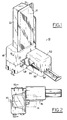
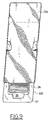
- a dispenser 10 designed to hold a dispensing tray 12 containing a stack of film packets 14.
- the film packets comprise x-ray film designed for use as is commonly used in the art.
- the tray comprises a bottom wall 16, an upper end wall 18, a lower end wall 20 which is substantially parallel to the upper end wall and a pair of substantially parallel side walls 22,24.
- the end walls 18,20 and side walls 22,24 merge at their juncture and extend from the bottom wall 16 terminating in an upper rim 26 to define an open top 28 and a recess 30 for receiving the stack of film packets 14.
- rim 26 has a substantially planar sealing surface 27.
- tray 12 is made of a plastic material which can be molded as a single unitary piece. In the particular embodiment illustrated, tray 12 is made of poly(ethylene terephalate) and is thermo-formed.
- the lower end wall 20 of tray 12 is provided with a pair of spaced support surfaces 32 which define an access opening 34 having a length L and a width W.
- the access opening 34 extends from the rim 26 to the bottom wall 16.
- the supporting surfaces 32 are designed to support the bottom packet of the stack of film packets 14.
- the support surfaces 32 are preferably disposed at a small angle ⁇ with respect to a plane perpendicular to the bottom wall 16 (see figure 7). In the particular embodiment illustrated angle ⁇ is 5 degrees. This small angle orientation assists in reducing the manufacturing cost of the tray 12.
- the access opening 34 is of a size which allows entry to access opening 32 either by the finger of a user or by other means for removing the bottom packet as is later discussed herein.
- the length L is 3/4 of an inch (1.905 cms) and the width W is 3/8 of an inch (.925 cms).
- the bottom section 35 of lower end wall 20, which forms part of access opening 34, is also inclined in a similar manner as support surfaces 32.
- Means are also provided on the bottom wall 16 for spacing the back edges 36 of the film packets 14 from the surface 38 of the bottom wall 16. In the particular embodiment illustrated, this is accomplished by providing the bottom wall 16 with a pair of spaced ribs 40 which are raised with respect to the bottom surface 38.
- the ribs 40 define a substantially central opening 41 which extends along the longitudinal length of the bottom wall 16 and form a rear space 42 behind the bottom packet.
- the ribs have a height so as to provide rear space 42 with a predetermined height H. In the particular embodiment illustrated, the ribs 40 provide a height H of 1/8 of an inch (0.3175 cms).
- the lower ends of the ribs 40 are flared out such that the width of the rear space 42 is substantially equal to the width of the access opening 34 at the point where they meet.
- the rear space 42 and access opening 34 allows access to the back edge 36 of the bottom packet 14.
- the corners 46 have a radius R such that the corners 46 extend below the surface of the adjacent support surfaces 32 so as to form supporting projections 47 disposed on both sides of access opening 34.
- radius R is 1/4 of an inch (0.635 cms).
- the dispenser 10 includes a shell support structure 48 which forms an internal chamber 49.
- shell support structure comprises a base 50 and a removable top 52 which combine to form the internal chamber 49.
- the base 50 and top 52 are made of a moldable material such as plastic for ease and low cost manufacture.
- base 50 and top 52 are made of a copolyester-polycarbonate material.
- the base 50 and top 52 may be made of any appropriate material.
- the base 50 and top 52 are shaped such that the internal chamber 49 comprises a rear section 56 for holding tray 12 in a substantially vertical orientation and a forward dispensing section 58 for allowing the dispensing of the packets in seriatim from the tray 12.
- the base 50 includes a bottom wall 64 having a pair of upwardly extending spaced projections 65, 67 for supporting the lower portion of the tray 12 in a substantially vertical position.
- the projections are positioned so that the upper end of projections 65, 67 is disposed at the forward corner areas of the lower end walls to provide a stable support surface.
- a rear projection 69 extends upwardly from the bottom wall 64 and is provided for assisting in maintaining the tray 12 in the substantially vertical position. Projection 69 is positioned such that it is adjacent the bottom wall 16 of the tray 12 when the tray 12 is placed in the dispenser 10.
- the bottom wall 64 of base 50 is preferably inclined at an angle ⁇ with respect to a plane which is perpendicular to the bottom wall 16 of the tray 12 when the tray 12 is mounted in the dispenser 10 in the substantially vertical position (see figures 6A-6C). As is discussed in greater detail later herein, orienting the bottom wall 64 in this manner assists in the removal of the bottom packet.
- the top 52 may be removably mounted to base 50 in any desired manner.
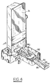
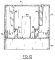
- the top 52 is secured to base 50 by a pair of downward extending latch members 60 which lock into openings 62 provided in projections 66, 68 which extends upwardly from the bottom wall 64, as best seen by reference to figure 10.
- a plurality of aligning pins 79 are also provided on base 50 which mate against the inside wall of top 52.
- An opening 74 is provided in top 52 for receiving tray 12.
- the opening 74 has a configuration which corresponds generally to the outer cross sectional configuration of the tray 12.
- the opening 74 is located in the rear section 56 such that when the lower portion of the tray 12 is placed through the opening 74 into the dispenser 10.
- the opening 74 and projections 65,67 and 69 work together to hold the tray 12 securely in the substantially vertical position as illustrated in figure 1.
- the opening 74 has a pair of narrow sections 75 designed to receive the generally planar rim 26 and is also located so that the rim 26 will be adjacent the front wall 77 of top 52. The positioning of rim 26 adjacent front wall 77 assists in maintaining the tray 12 in the substantially vertical position, maintaining the packets 14 in the tray 12 and dispensing only the bottom packet as is discussed later herein.
- the forward dispensing section 58 of the dispenser is provided with means for removing the film packets 14 from tray 12 in seriatim.
- the means for removing the film packets comprises a stripper mechanism 82 having a dispensing member 84.
- dispensing member 84 is made of a plastic material.
- the dispensing member 84 may be made of any appropriate material.
- a clip 86 is disposed at one end of the dispensing member 84 for insertion into access opening 34 in the bottom of lower end wall 20 of the tray 12.
- the clip 86 comprises a support surface 87 for supporting a single packet and dispensing the packet from the dispenser 10.
- the support surface 87 is shaped such that a packet 14 will remain thereon when removed from the dispenser or will fall off in a predetermined direction.
- the surface has a generally rectangular shape having a length L1 of 3/8 inches (.9525 cms) and a width W1 of 3/4 inches (1.905 cms) so as to accommodate a film packet having size of 1 1/4 inches by 1 3/4 inches (3.175 by 4.445 cms).
- the particular size and shape of support surface 87 may be varied to accommodate any size or shape film packet.
- Clip 86 is provided with a generally planar retaining finger 88 at its forward terminal end 90 for placement behind the back edge 36 of the bottom packet 14.
- the retaining finger 88 has a configuration such that only the bottom packet will be captured between the retaining finger 88 and clip 86.
- the retaining finger 88 is disposed at an angle ⁇ of 45° with respect to the top surface of the clip 86 and extends a distance such that the terminal end 91 of the retaining finger 88 is spaced a distance H2 above the surface 87 of clip 86. It is to be understood that the retaining finger 88 may be modified so as to accommodate any size or type film packet.
- the dispensing member 84 further includes an arm 92 having one end connected to the rear end of clip 86.
- the arm 92 is displaced a distance D1 below the top surface of the clip 86 so as not to interfere with the stack of film packets and the dispensing of the film packet on support surface 87.
- the distance D1 is preferably of 1/4 of an inch (0.636 cms) or greater. In the particular embodiment illustrated, the distance D1 is approximately 1/4 inches (0.635 cms).
- Dispensing member 84 further includes a gripping section 94 located at the rear of arm 92 which is slideably mounted to the base 50 by a pair of spaced parallel channels 96 formed in the bottom wall 64 of base 50 which are designed to receive and retain the side edges 95 of the gripping section 94. It is to be understood that the dispensing member 84 may be slideably mounted to the dispenser in any desired manner.
- Channels 96 are disposed such that the dispenser member 84 moves in a direction substantially perpendicular to the tray 12 so as to allow the clip 86 to pass through access opening 34 and go into the rear space 42 behind the bottom packet and allow dispensing of the bottom packet from the tray 12.
- the hand gripping section 94 extends through an appropriately placed and sized opening 97 provided in dispenser 10 between the top 52 and base 50.
- a dispensing opening 99 of an appropriate size and shape is provided in dispenser 10 for allowing dispensing of the bottom packet after it has been removed from the tray 12 by dispensing member 84.
- the dispensing and rear sections 56, 58 have a configuration such that opening 99 allows dispensing of the bottom packet on one side of dispensing section 58 as illustrated in figure 1.
- the opening 99 in front wall 77 is positioned such that only the bottom packet of the stack may pass therethrough. The packets above the bottom packet are prevented from any forward movement by front wall 77.
- a return spring 98 is provided so as to maintain the dispensing member 84 at a predetermined position.
- spring 98 is designed to bias the clip 86 in the dispensing position as illustrated in figure 6A.
- the return spring 98 has one end 100 secured to the base 50 and a second end 102 secured to the dispensing member 84 at any convenient location so that the clip 86 and retaining finger 88 are normally positioned in front of the bottom packet as shown in figures 6A.
- spring 98 is illustrated as a compression spring.
- a tension spring or any desired means may be provided to bias the dispensing member at the desired position. While the spring 98 is desirable for biasing the dispensing member 84 at a predetermined position, if desired, the spring 98 may be omitted leaving the operator to move dispensing member 84.
- a back plate 104 is secured to the base 50 and top 52 and is designed to engage a mounting plate 106.
- the mounting plate 106 is designed to be mounted to a wall or other fixture.
- the mounting plate 106 is provided with a pair of vertically spaced openings 108 designed to receive mounting projections (not shown) provided on back plate 104.
- the dispenser 10 is mounted to the mounting plate 106 by simply moving the dispenser in a downward direction so as to lock the dispenser thereon. In order to remove the dispenser, the dispenser is simply lifted upward and then removed from the mounting plate 96.
- an optional shield 110 designed to be placed on the dispenser 10 such that the packets 14 within the tray 12 are protected from stray x-ray radiation.
- the shield 110 is secured to the base 50 by a plurality of projections 112 provided on the shield which mate into corresponding slot or openings 114 provided on the outer surface of the peripheral wall of base 50.
- the shield 110 may be secured to the dispenser 10 in any desired manner.
- a tray 12 having a stack of film packets 14 is provided.
- the packets in the particular embodiment illustrated are dental x-ray film packets designed to be used in the mouth of a patient.
- the peelable cover 31 adjacent the lower end wall is peeled back a sufficient distance so as to expose at least the bottom packet. Typically, the cover would first be peeled off so as to expose 5 to 10 packets in the lower portion of the tray 12. The cover 31 should not be peeled back too far so as to expose the packets above the front wall 77 when the tray is positioned within the dispenser 10.
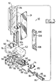
- the tray 12 with the exposed packets 14 is then placed through opening 74 into the dispenser 10 and properly seated, as illustrated in Figure 2.
- the stripper member is pushed forward so as to cause the clip 84 to engage the bottom packet from the stack of packets and allow removal of the bottom packet out of opening 99 and dispensing of the packet to the user.
- FIGS 6A-6C there is illustrated the relative position of the clip 86 as it moves from the dispensing position illustrated in figure 6A to the film packet engaging position illustrated in Figure 6C.
- the spring 98 biases the dispensing member 84 such that the clip 86 is normally positioned in the dispensing position.
- the operator pushes on the gripping section 84 of the stripper member so as to cause the clip 86 to move through the access opening 34, as shown in figure 6B, and back into rear space 42 as shown in figure 6C where it engages the bottom packet.
- the operator then allows the spring, if present, to move the stripper member to the dispensing position.
- the forward section 58 of the dispenser is designed such that the packet being dispensed will be in the position as illustrated in Figure 2.
- the side wall 81 of forward dispensing section 58 is located such that a sufficient amount of the packet will extend out of the opening 99 adjacent side wall 81 so as to allow easy access to the packet.
- the side wall 81 of forward dispensing section is located at about the mid-center line 111 of the tray 12 or above the mid-center line 111 as viewed in figure 2.
- the packet may be removed by hand or optionally, the clip 86 can be designed such that when a packet is in the dispensing position it will easily fall off the clip 86.
- the cross-sectional area of the surface 87 of the clip 86 is designed such that when the gripping section 94 of the dispensing member 84 is pulled outwardly in a quick manner, the jarring force of the gripping member reaching the dispensing position will cause the packet to fall from the clip 86 into a cup or other container positioned underneath by the user.
- Applicants have found that by properly designing the shape and size of clip 86 and opening 99 only a small amount of jarring is required to cause the packet to fall off the clip 86.
- the clip 86 is designed such that it will have an interference travel as it moves to the engaging position.
- the bottom wall 64 of the base 50 is disposed at an angle ⁇ of 6° with respect to a plane substantially perpendicular to the bottom surface of the tray 12. This will cause the clip 86 to move at a 6° angle as it is moved from the dispensing position to the engaging position.
- the lower end wall of the tray 12, as previously discussed, is disposed at an angle ⁇ of approximately 5° with respect to the bottom wall.
- This interference movement assists the retaining finger in properly seating behind the bottom packet by generating a spring force in the arm 92 as it travels to the engaging position. This spring force is applied to the bottom of the packet to ensure that the clip and retaining finger properly engages the bottom packet.
- the tray 12 may be place in a drawer or other confined area where the packets 14 can be removed individually by hand.
- the peelable cover 31 is at least partially removed and the bottom wall 16 of the tray placed on a supporting surface.
- a first packet can be removed by placing the finger within the access opening 34 and pulling out a first packet. The remaining packets are removed in like manner.
- the ribs 40 may be eliminated.
- the ribs 40 assist in removing a packet when it is lying flat on the bottom wall 16 by allowing the finger of the user to reach beneath the packet.
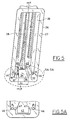
- a modified tray 120 made in accordance with the present invention.
- Tray 120 is similar to tray 12, like numerals indicating like parts.
- a slideable cover 124 is provided which is designed to engage rim 26.
- the sides of the cover 124 is simply folded over so as to capture the rim 26 as shown by the broken away sections.
- the slideable cover 124 is opened and closed as required by the user.
- the cover 124 is simply slid an appropriate distance to allow the bottom packets to be exposed. If the tray 120 is placed in a drawer and the packets removed directly therefrom, the cover 124 is simply slid open the required distance so that the desired number of packets can be removed. The cover 124 can then be closed so as to maintain the cleanliness of the packets.
- the invention is summerized as follows:
Landscapes
- Engineering & Computer Science (AREA)
- Physics & Mathematics (AREA)
- General Physics & Mathematics (AREA)
- Microelectronics & Electronic Packaging (AREA)
- Health & Medical Sciences (AREA)
- General Health & Medical Sciences (AREA)
- Oral & Maxillofacial Surgery (AREA)
- Mechanical Engineering (AREA)
- Containers And Packaging Bodies Having A Special Means To Remove Contents (AREA)
- Automatic Analysis And Handling Materials Therefor (AREA)
- De-Stacking Of Articles (AREA)
- Apparatus For Radiation Diagnosis (AREA)
Applications Claiming Priority (2)
| Application Number | Priority Date | Filing Date | Title |
|---|---|---|---|
| US893186 | 1992-06-03 | ||
| US07/893,186 US5265760A (en) | 1992-06-03 | 1992-06-03 | Individual film packet dispenser and tray dispenser |
Publications (1)
| Publication Number | Publication Date |
|---|---|
| EP0572899A1 true EP0572899A1 (fr) | 1993-12-08 |
Family
ID=25401161
Family Applications (1)
| Application Number | Title | Priority Date | Filing Date |
|---|---|---|---|
| EP93108391A Withdrawn EP0572899A1 (fr) | 1992-06-03 | 1993-05-25 | Distributeur de paquets utilisant un emballage de paquets |
Country Status (4)
| Country | Link |
|---|---|
| US (2) | US5265760A (fr) |
| EP (1) | EP0572899A1 (fr) |
| JP (1) | JPH0664754A (fr) |
| CA (1) | CA2097241A1 (fr) |
Cited By (2)
| Publication number | Priority date | Publication date | Assignee | Title |
|---|---|---|---|---|
| NL1015658C2 (nl) * | 2000-07-07 | 2002-01-08 | Vdv Innovatietechniek B V | Distributieinrichting en cassette daarvoor. |
| WO2005007533A1 (fr) * | 2003-07-16 | 2005-01-27 | Il Young Enterprise Co., Ltd. | Recipient distributeur de pastilles avec dispositif distributeur dans la partie inferieure |
Families Citing this family (13)
| Publication number | Priority date | Publication date | Assignee | Title |
|---|---|---|---|---|
| DE4314696C2 (de) * | 1993-05-04 | 1996-12-19 | Uhlmann Pac Systeme Gmbh & Co | Magazinvorrichtung für Faltschachteln bei Verpackungsmaschinen mit verstellbarem Magazinschacht |
| US5503298A (en) * | 1994-11-21 | 1996-04-02 | Herman; Richard J. | Bagel dispenser |
| US6141942A (en) * | 1997-11-28 | 2000-11-07 | Diebold, Incorporated | Apparatus and method for loading medical items in a dispenser module |
| US6234343B1 (en) * | 1999-03-26 | 2001-05-22 | Papp Enterprises, Llc | Automated portable medication radial dispensing apparatus and method |
| US7063234B2 (en) * | 2000-12-29 | 2006-06-20 | Csp Technologies, Inc. | Meter strip dispenser assembly |
| WO2003030112A2 (fr) * | 2001-10-01 | 2003-04-10 | Frank Runnels | Distributeur d'articles plats |
| US20050183391A1 (en) * | 2004-02-19 | 2005-08-25 | Chouinard Richard J. | Wrap device to facilitate handling of stacked slides or other stackable flat objects |
| US8019471B2 (en) | 2004-04-24 | 2011-09-13 | Inrange Systems, Inc. | Integrated, non-sequential, remote medication management and compliance system |
| US7828147B2 (en) | 2004-04-24 | 2010-11-09 | Inrange Systems, Inc. | Multi-layer medication carrier |
| CN1953915A (zh) * | 2004-04-24 | 2007-04-25 | 鹰锐系统股份有限公司 | 通用药物承载器 |
| US20110017768A1 (en) * | 2009-07-20 | 2011-01-27 | Antonio Vardaro | Vertical small packet dispenser |
| US9049948B2 (en) | 2012-01-27 | 2015-06-09 | Us Foods, Inc. | Utensil dispenser |
| GB2529667B (en) * | 2014-08-28 | 2020-06-24 | Pyramid Innovation Ltd | A device and method for delivering a laboratory sample carrier from a stack of sample carriers |
Citations (3)
| Publication number | Priority date | Publication date | Assignee | Title |
|---|---|---|---|---|
| US2286010A (en) * | 1941-03-14 | 1942-06-09 | Rabkin William | Supply container for photographic plates |
| DE1226484B (de) * | 1964-11-16 | 1966-10-06 | Dow Chemical Co | Verteilervorrichtung |
| FR2215819A5 (fr) * | 1973-01-26 | 1974-08-23 | Michel Marcel |
Family Cites Families (31)
| Publication number | Priority date | Publication date | Assignee | Title |
|---|---|---|---|---|
| US402374A (en) * | 1889-04-30 | Vending apparatus | ||
| US949223A (en) * | 1909-03-06 | 1910-02-15 | James L Dunning | Match-safe. |
| US1723232A (en) * | 1925-09-02 | 1929-08-06 | Philip A Fischer | Sanitary package for drinking cups and dispensing device |
| US1751169A (en) * | 1927-06-23 | 1930-03-18 | Ohio Match Company | Vending machine |
| US1888314A (en) * | 1931-01-30 | 1932-11-22 | Arthur M Framke | Make-up applicator |
| US1973867A (en) * | 1932-12-27 | 1934-09-18 | Frank M Cook | Dispensing device |
| US2282036A (en) * | 1938-11-07 | 1942-05-05 | Cobbs John James | Cigarette case |
| US2247834A (en) * | 1940-02-26 | 1941-07-01 | Jr Charles A Davis | Cracker dispenser |
| US2434785A (en) * | 1945-08-23 | 1948-01-20 | Max E Blumenstein | Picture slide feeding mechanism |
| US2626192A (en) * | 1950-06-29 | 1953-01-20 | Westinghouse Electric Corp | Oil-pot for vertical-shaft machines |
| US2626197A (en) * | 1950-08-31 | 1953-01-20 | George J Kollock | Photographic slide ejectorreceptacle |
| US2707066A (en) * | 1953-12-07 | 1955-04-26 | Stegeman Wilson | Reversible ejector-type article dispenser |
| US3168965A (en) * | 1961-09-22 | 1965-02-09 | Rinn Corp | Dental film pack dispensers, and the like |
| US3161320A (en) * | 1962-07-30 | 1964-12-15 | Clifford D Swanson | Article dispenser having article withdrawing means |
| US3224822A (en) * | 1963-11-08 | 1965-12-21 | Bi Fresh Dispenser Co | Reusable display and dispensing container |
| US3412895A (en) * | 1965-12-20 | 1968-11-26 | Kwik Lok | Dispenser for closure device with price tag |
| US3351233A (en) * | 1966-02-21 | 1967-11-07 | Lawrence H Chanoch | Refrigerated food dispenser having a reciprocating ejector |
| US4032485A (en) * | 1975-02-27 | 1977-06-28 | Miyoshi Yushi Kabushiki Kaisha | Polyurethane foams based on mixed itaconic acid polyesters |
| DE7535699U (de) * | 1975-11-10 | 1976-03-04 | Siemens Ag, 1000 Berlin Und 8000 Muenchen | Filmpackung fuer intraorale zahnroentgenaufnahmen |
| US4043485A (en) * | 1976-08-09 | 1977-08-23 | Honeywell Information Systems, Inc. | Magazine for a plurality of fixtures holding integrated circuit chips |
| JPS60143398U (ja) * | 1984-03-05 | 1985-09-24 | 三菱電線工業株式会社 | 遮蔽材 |
| US4795654A (en) * | 1984-11-05 | 1989-01-03 | Innofinance Altalanos Innovacios Penzintezet | Structure for shielding X-ray and gamma radiation |
| US4805201A (en) * | 1985-04-22 | 1989-02-14 | Strong Grainger Vonda | Intraoral dental radiographic film packet pad |
| GB8529553D0 (en) * | 1985-11-30 | 1986-01-08 | Kuckelmann H | Ticket dispensing machine |
| JPH0410596Y2 (fr) * | 1986-06-17 | 1992-03-16 | ||
| US4767022A (en) * | 1986-10-31 | 1988-08-30 | Dennis Oldorf | Packet dispenser |
| US4791657A (en) * | 1987-11-06 | 1988-12-13 | Alan Kirsch | Intraoral radiographic film packet |
| US4912740A (en) * | 1988-08-19 | 1990-03-27 | Eastman Kodak Company | Intraoral dental radiographic film packet improvement |
| US4922511A (en) * | 1988-11-21 | 1990-05-01 | Eastman Kodak Company | Dental film packet |
| US4951305A (en) * | 1989-05-30 | 1990-08-21 | Eastman Kodak Company | X-ray grid for medical radiography and method of making and using same |
| US5077779A (en) * | 1991-01-24 | 1991-12-31 | Eastman Kodak Company | Dental film packet improvement and method for effecting same |
-
1992
- 1992-06-03 US US07/893,186 patent/US5265760A/en not_active Expired - Fee Related
-
1993
- 1993-05-25 EP EP93108391A patent/EP0572899A1/fr not_active Withdrawn
- 1993-05-28 CA CA002097241A patent/CA2097241A1/fr not_active Abandoned
- 1993-05-31 JP JP5128928A patent/JPH0664754A/ja active Pending
- 1993-07-26 US US08/103,361 patent/US5323920A/en not_active Expired - Fee Related
Patent Citations (3)
| Publication number | Priority date | Publication date | Assignee | Title |
|---|---|---|---|---|
| US2286010A (en) * | 1941-03-14 | 1942-06-09 | Rabkin William | Supply container for photographic plates |
| DE1226484B (de) * | 1964-11-16 | 1966-10-06 | Dow Chemical Co | Verteilervorrichtung |
| FR2215819A5 (fr) * | 1973-01-26 | 1974-08-23 | Michel Marcel |
Cited By (3)
| Publication number | Priority date | Publication date | Assignee | Title |
|---|---|---|---|---|
| NL1015658C2 (nl) * | 2000-07-07 | 2002-01-08 | Vdv Innovatietechniek B V | Distributieinrichting en cassette daarvoor. |
| EP1182623A1 (fr) * | 2000-07-07 | 2002-02-27 | VDV Innovatietechniek B.V. | Dispositif de distribution et sa cassette |
| WO2005007533A1 (fr) * | 2003-07-16 | 2005-01-27 | Il Young Enterprise Co., Ltd. | Recipient distributeur de pastilles avec dispositif distributeur dans la partie inferieure |
Also Published As
| Publication number | Publication date |
|---|---|
| JPH0664754A (ja) | 1994-03-08 |
| US5323920A (en) | 1994-06-28 |
| CA2097241A1 (fr) | 1993-12-04 |
| US5265760A (en) | 1993-11-30 |
Similar Documents
| Publication | Publication Date | Title |
|---|---|---|
| US5265760A (en) | Individual film packet dispenser and tray dispenser | |
| US5494162A (en) | Package and method for delivering a medical implant | |
| CN1318143C (zh) | 微量吸管容器 | |
| JP4146718B2 (ja) | 薄板支持容器 | |
| US6007779A (en) | Refill pack for pipette tip racks | |
| US5948362A (en) | Device for arranging a plurality of objects on a support | |
| US5100018A (en) | Probe cover dispenser | |
| US20050051454A1 (en) | Case with pill receiving sleeves for storing and dispensing pills | |
| US20110162325A1 (en) | Packing of boxed gloves | |
| JPS63272686A (ja) | 電子部品チツプ収納カセツト | |
| US5447253A (en) | Condom dispenser | |
| JP4296296B2 (ja) | 薄型ウエハー挿入体 | |
| US20090277816A1 (en) | Top Flange Protective Cover for Thin Plate Container and Thin Plate Container Provided Therewith | |
| EP0629554A1 (fr) | Appareils pour presser des objets hors d'un emballage blister | |
| WO1999039994A1 (fr) | Receptacle support de feuille | |
| US6640995B2 (en) | Contact lens dispensing system | |
| US7264140B1 (en) | System and method for dispensing pharmaceutical samples | |
| EP0549484B1 (fr) | Procédé et appareil flexible pour introduire des emballages de dimensions différentes dans des boîtes du type "manchon" | |
| US9221632B2 (en) | Media cassette loader | |
| JPH05507001A (ja) | 汚染防護性歯科矯正具ディスペンサー | |
| US3446543A (en) | Method of dispensing milk filter disks and apparatus therefor | |
| WO1999054209A1 (fr) | Distributeur de medicaments | |
| KR200369928Y1 (ko) | 약포지의 개구 단부 개방장치 | |
| JP2001007178A (ja) | ウエハ移載装置 | |
| US20250289642A1 (en) | Funnel storage systems and methods thereof |
Legal Events
| Date | Code | Title | Description |
|---|---|---|---|
| PUAI | Public reference made under article 153(3) epc to a published international application that has entered the european phase |
Free format text: ORIGINAL CODE: 0009012 |
|
| AK | Designated contracting states |
Kind code of ref document: A1 Designated state(s): CH DE FR GB IT LI |
|
| 17P | Request for examination filed |
Effective date: 19940511 |
|
| 17Q | First examination report despatched |
Effective date: 19960621 |
|
| GRAG | Despatch of communication of intention to grant |
Free format text: ORIGINAL CODE: EPIDOS AGRA |
|
| 18W | Application withdrawn |
Withdrawal date: 19970123 |