EP0572901A1 - Glissière pour tiroirs - Google Patents
Glissière pour tiroirs Download PDFInfo
- Publication number
- EP0572901A1 EP0572901A1 EP93108413A EP93108413A EP0572901A1 EP 0572901 A1 EP0572901 A1 EP 0572901A1 EP 93108413 A EP93108413 A EP 93108413A EP 93108413 A EP93108413 A EP 93108413A EP 0572901 A1 EP0572901 A1 EP 0572901A1
- Authority
- EP
- European Patent Office
- Prior art keywords
- drawer
- guide
- rollers
- swivel arms
- guide rails
- Prior art date
- Legal status (The legal status is an assumption and is not a legal conclusion. Google has not performed a legal analysis and makes no representation as to the accuracy of the status listed.)
- Granted
Links
Images


Classifications
-
- A—HUMAN NECESSITIES
- A47—FURNITURE; DOMESTIC ARTICLES OR APPLIANCES; COFFEE MILLS; SPICE MILLS; SUCTION CLEANERS IN GENERAL
- A47B—TABLES; DESKS; OFFICE FURNITURE; CABINETS; DRAWERS; GENERAL DETAILS OF FURNITURE
- A47B88/00—Drawers for tables, cabinets or like furniture; Guides for drawers
- A47B88/40—Sliding drawers; Slides or guides therefor
- A47B88/433—Drawers with a couple of pivotally retractable, roller-supporting arms at the rear of the drawer, e.g. for curved slides or guides
Definitions
- the invention relates to a drawer slide and in particular a drawer slide as a simple pull-out.
- Drawer guides as single pull-out have furniture-side guide rails and drawer-side pull-out rails.
- a support roller is attached to the guide rails at the front end, on which the drawer-side extension rail is supported. From the rear end of the drawer there are projections on which there are rollers that are guided in the guide rails.
- the drawer When the drawer is pulled out, it bumps against a stop if the rollers are still a bit in the guide rails. The weight of the drawer is then supported by the support rollers, while the rollers prevent the drawer from tipping down.
- the drawer When fully extended, the drawer is dimensioned such that the drawer box in its entire useful depth from the Furniture can be pulled out so that the inside of the drawer box is fully accessible from above, while a support structure attached to the drawers is still inside the cabinet.
- Such drawer runners are those in which the drawer can be pulled out of the cabinet so far that the rear wall of the drawer box is still in front of the cabinet cover.
- the further a drawer can be pulled out of the cabinet the longer the support structure protruding from the drawer must be.
- the cabinet depth must be such that it is equal to the depth of the drawer box plus the length of the support structure. This means that only part of the cabinet depth can be used.
- the preamble of claim 1 is based on a drawer guide as is known from DE 90 12 423 U.
- the support structure supporting the drawer when it is pulled out consists of swivel arms which are attached to the rear end of the drawer and which are pivoted inwards when the drawer is pushed in, in order to reduce the effective drawer length when pushed in, and thus also the required cabinet depth.
- the roller which is normally attached to a rigid rear extension of the drawer, is attached to a swivel arm.
- the swivel arms and the drawer have interlocking locking elements which keep the swivel arms locked in the stretched state when the rollers are guided within the guide rails.
- the swivel arms When the drawer is almost fully inserted, the swivel arms are unlocked by passing control cams. Then the swivel arms are transferred from the guide rails to guideways, which cause the swivel arms to pivot inwards in the end position of the drawer. When the swivel arms are swiveled inwards, the drawer is supported by additional auxiliary rollers at its end. The smooth movement of the drawer at the end of the insertion movement is impaired by the control cams, and it can happen that the drawer stops shortly before its end position. In this case, the drawer must be closed manually to reach the full insertion position.
- a further disadvantage is that the swivel arms can be moved within limits along their swivel axes or tilted in the vertical plane in order to effect the locking and unlocking.
- the swivel arms also have an additional degree of freedom. This reduces the stability of the drawer guide and makes it difficult to manufacture with the required tolerances.
- the invention has for its object to provide a drawer guide of the type specified in the preamble of claim 1, i.e. a drawer guide that requires a small cabinet depth when the drawer can be pulled out further, in which, despite the pivotability of the swivel arms carrying the castors, stable guide behavior when the drawer is pulled out is guaranteed.
- the drawer guide according to the invention is characterized in that the guide rails on their inside have an oblique guide web, the roller pulled outwards at least in the end region of the extension length.
- the swivel arms are pulled by the rollers against stops, so that the mobility of the swivel arms in the swivel plane is increasingly restricted.
- the distance between the center of gravity of the drawer and the support rollers increases, so that the rollers are pressed against the upper legs of the C-shaped guide rail from below with increasing force.
- the inner edge of the running surface of the roller is pressed outward against the stop, as a result of which the swivel arm is fixed in the extended state.
- the castors are not loaded and they are guided loosely in the guide rails.
- the swivel arms which generally point in the longitudinal direction of the drawer, are pressed against the stops by the oblique guide webs of the guide rails by the loading moment of the drawer and are thereby made rigid with respect to the drawer.
- Each of the swivel arms can be swiveled in the manner of a knee joint, i.e. it can only be swiveled inwards, but not beyond the stretched state.
- the outward swing is limited by the stop. If a horizontal transverse force acts on the drawer when the drawer is pulled out far, the drawer is blocked by the swivel arm which lies back in the direction of the force effect and which is pressed firmly against its stop under this load, while the swivel arm which is forward in the direction of force can yield.
- the pull-out rails preferably grip around the support rollers from above and they have inclined guide webs on both sides of the support rollers.
- the sloping guide bars also stabilize the drawer against lateral forces.
- the swivel arms are expediently slightly flexible or torsionally flexible, so that they are clamped between the stops and the inner leg of the guide rail when the drawer is pulled out.
- the swivel arms can also be rigid if the stops have a corresponding flexibility or elasticity.
- the swivel axes of the swivel arms are arranged obliquely on the drawer in such a way that they are pressed outwards against the stop when their rollers are loaded vertically. Due to the oblique arrangement of the The swivel arms are already pushed outwards by their own weight, so that they rest against the stops. This avoids pendulum movements of the unloaded roller in the track. If the castors and swivel arms are loaded when the drawer is pulled out, the pressing of the swivel arms against the stops is increased by the horizontal force component caused by the inclined position of the swivel axes.
- a particular advantage of the invention is that the swivel arms require only a single degree of freedom, namely the pivotability about their swivel axes, but that the swivel arms do not have to be displaceable along the swivel axes or tiltable in the vertical plane. As a result, the stability of the side guide can be increased with little production effort.
- the drawer guide according to the invention is particularly suitable for pharmacy drawers.
- Pharmacy drawers are characterized by a relatively large length with a usable depth in the range of approximately 1.00 m and a total length of approximately 1.25 m.
- Another special feature of pharmacy drawers is that the pull-out rails on the drawer box have to be arranged at a low height above the floor so that the side walls offer space for attaching card pockets for receiving label holders.
- Those drawers that are arranged at eye level usually have a transparent bottom.
- Another feature of pharmacy drawers is a slope in the drawer guide in order to achieve an automatic entry into the closed position.
- drawer guide according to the invention is not restricted to pharmacy cabinets.
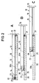
- the drawer guide shown in FIG. 1 has a drawer 12 with parallel side walls 13, a rear wall 14, a front wall to which an exchangeable panel 15 is attached, and a bottom wall 16.
- the interior of the drawer box 12 can be divided into compartments by means of displaceable dividing walls, which are used to hold various medicines.
- Along the side walls 13 each have a horizontal pull-out rail 19 which projects outwards.
- Two guide rails 20 with a laterally open C-profile are provided for each drawer and can be mounted in a cabinet (not shown).
- a support roller 21 is mounted on the front end of each guide rail 20.
- the pull-out rail 19 rests on the support roller 21 which projects upward above the guide rail.
- the side walls 13 are extended towards the rear beyond the rear wall 14 and they carry holders 22 there, on each of which a pivot arm 23 is attached so as to be pivotable about a vertical pivot axis 24.
- the pivot arms 23 are pivotable between a first position in which they extend in the longitudinal direction of the drawer and extend it to the rear, and a second position in which they are pivoted inwards, so that the holders 22 form the rear end of the drawer 12.
- a roller 25 is mounted on a protruding pin. This roller runs in a guide rail 20 and can therefore press from below against the upper running surface of this guide rail.
- the two guide rails 20 are connected to one another by a cross member 28 with guide tracks 26.
- Guide pieces 27 protrude from the inside of the swivel arms 23, which are arranged shortly in front of the rollers 25 and which can come into engagement with a guide track 26, shortly before the insertion movement of the drawer ends to pivot the pivot arms 23 against each other (inwards), so that the pivot arms assume a pivoted-in state when the drawer is inserted.
- the swivel arms here have a length which corresponds to approximately half the width of the drawer, but the length of the swivel arms can also be greater, the swivel arms then overlapping when folded. So that the rollers 25 can leave the C-shaped guide rails 20 shortly before the end of the insertion movement of the drawer, the guide rails have corresponding openings at the end region from which the rollers 25 can emerge laterally.
- auxiliary rollers 29 which are mounted on the extensions of the side walls 13 in the rear region of the drawer box .
- the auxiliary rollers 29 do not engage in the guide rails 20, but run on the upper leg 20a, which forms the upper of the two horizontal legs of the guide rail.
- the auxiliary rollers 29 thus run freely on the upper running leg 20a of the guide rail without being secured against being lifted off the running leg.
- rollers 25 only take on the load when the center of gravity of the drawer has exceeded the support rollers 21, which is the case in position C of FIG. 2. Then the rollers are pressed from below against the respective legs 20a of the guide rail 20 and the auxiliary rollers 29 lift off the legs. When the drawer is pulled out further, it is supported by the support rollers 21, while the rear end of the drawer is held down by the rollers 25.
- a deflector 31 is provided directly behind the support roller 21, which protrudes laterally obliquely towards the front and inwards from the outer wall of the guide rail 20.
- the deflector 31 thus projects into the interior of the guide rail, so that the roller 25 guided in the guide rail 20 abuts the deflector 31 when the drawer is removed from the guide.
- the guide rail 20 is open inwards, so that the roller 25 can leave the guide rail inwards.
- the pivot arm 23 is thereby pivoted inwards. In this way, the drawer can be easily removed from the guide.
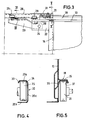
- the C-shaped guide rail 20 has an upper leg 20a and a lower leg 20b and a vertical base 20c.
- the upper running leg 20a has two inclined guide webs 33, 34, of which the guide web 34 forms the transition to the base 20c, while the guide web 33 encompasses the upper end of the roller 25.
- the lower running leg 20b runs horizontally, but it can also have a web that surrounds the running roller 25.
- the lateral track play of the roller 25 in the guide rail 20 is as narrow as is necessary for the roller 25 to run freely.
- the rollers 25 When the drawer is in the largely inserted state, the rollers 25 are relieved, so that they are at a distance from the two legs 20a and 20b.
- the rollers 25 When the drawer is pulled out, on the other hand, the rollers 25 are pressed against the legs 20a from below, the inner edge of the roller pressing against the inclined inner guide web 33 and the roller being pressed outwards by this guide web 33.
- the roller 25 pulls the swivel arm 23 outwards and thereby presses it firmly against the stop 30. As a result, the swivel arm 23 of the drawer is fixed in the extended state.
- the swivel arms 23 are expediently flexible or torsionally flexible and / or the stops 30 yield elastically in order to avoid jamming of the rollers in the guide rails.
- the swivel arms 23 can only be swiveled about their swivel axes 24, so they have no degree of freedom in a vertical plane.
- Each of the swivel arms is after Kind of a knee joint can only be pivoted inwards, ie it cannot be pivoted outward beyond the stretched state.
- the interaction of the guide web 33 and the stop 30 makes the knee stiff in the stretched state.
- FIG. 5 shows a side wall 13 of the drawer box 12 with the pull-out rail 19 protruding therefrom, which is carried by the support roller 21.
- the pull-out rail 19 is double-walled and bent out of the material of the side wall 13. It has a horizontal upper running leg 35 and two guide webs 36 and 37 projecting obliquely downward on both sides thereof.
- the pull-out rail 19 engages around the support roller 21 from above, i.e. it is wider than the support roller.
- the horizontal part of the underside of the running leg 35 has a width which essentially corresponds to the width of the support roller 21.
- Fig. 6 shows a rear view of a modified drawer 12.
- This embodiment differs from the previous one in that the pivot axes 24 are not arranged vertically, but are inclined in a transverse plane of the drawer.
- the pivot axes 24 are arranged in a V-shape, ie they converge downwards. 4 is pressed from below against the running leg 20a of the guide rail 20 when the drawer is pulled out, an outward force component acts on the swivel arm 23 due to the inclined position of its swivel axis 24, which additionally presses the swivel arm against the Stop 30 presses.
Landscapes
- Drawers Of Furniture (AREA)
- Vehicle Step Arrangements And Article Storage (AREA)
Applications Claiming Priority (2)
| Application Number | Priority Date | Filing Date | Title |
|---|---|---|---|
| DE9207462U | 1992-06-03 | ||
| DE9207462U DE9207462U1 (de) | 1992-06-03 | 1992-06-03 | Schubladenführung |
Publications (2)
| Publication Number | Publication Date |
|---|---|
| EP0572901A1 true EP0572901A1 (fr) | 1993-12-08 |
| EP0572901B1 EP0572901B1 (fr) | 1996-09-11 |
Family
ID=6880153
Family Applications (1)
| Application Number | Title | Priority Date | Filing Date |
|---|---|---|---|
| EP93108413A Expired - Lifetime EP0572901B1 (fr) | 1992-06-03 | 1993-05-25 | Glissière pour tiroirs |
Country Status (4)
| Country | Link |
|---|---|
| EP (1) | EP0572901B1 (fr) |
| AT (1) | ATE142445T1 (fr) |
| DE (2) | DE9207462U1 (fr) |
| ES (1) | ES2093879T3 (fr) |
Cited By (1)
| Publication number | Priority date | Publication date | Assignee | Title |
|---|---|---|---|---|
| DE20312396U1 (de) * | 2003-08-12 | 2004-12-23 | Gebr. Willach Gmbh | Schubladenführung |
Citations (1)
| Publication number | Priority date | Publication date | Assignee | Title |
|---|---|---|---|---|
| EP0473060A1 (fr) * | 1990-08-30 | 1992-03-04 | GEBR. WILLACH GmbH | Dispositif de guidage pour tiroirs |
Family Cites Families (5)
| Publication number | Priority date | Publication date | Assignee | Title |
|---|---|---|---|---|
| AT323364B (de) * | 1972-12-22 | 1975-07-10 | Fulterer Karl Dr | Auszug mit laufrollen für ausziehbare möbelteile |
| DE2420307A1 (de) * | 1974-04-26 | 1976-03-25 | Wilhelm Pollmaier Fa | Rollenfuehrung fuer moebelschubkaesten |
| DE3640253A1 (de) * | 1986-11-28 | 1988-06-09 | Hagenhenrich Gmbh & Co Kg | Seitengefuehrte auszugfuehrung |
| DE3703051A1 (de) * | 1987-02-03 | 1988-08-11 | Lautenschlaeger Kg Karl | Ausziehfuehrung |
| DE8803088U1 (de) * | 1988-03-08 | 1988-06-23 | Ziehl, Gustav, 5000 Köln | Schubkasten |
-
1992
- 1992-06-03 DE DE9207462U patent/DE9207462U1/de not_active Expired - Lifetime
-
1993
- 1993-05-25 ES ES93108413T patent/ES2093879T3/es not_active Expired - Lifetime
- 1993-05-25 EP EP93108413A patent/EP0572901B1/fr not_active Expired - Lifetime
- 1993-05-25 AT AT93108413T patent/ATE142445T1/de not_active IP Right Cessation
- 1993-05-25 DE DE59303718T patent/DE59303718D1/de not_active Expired - Lifetime
Patent Citations (1)
| Publication number | Priority date | Publication date | Assignee | Title |
|---|---|---|---|---|
| EP0473060A1 (fr) * | 1990-08-30 | 1992-03-04 | GEBR. WILLACH GmbH | Dispositif de guidage pour tiroirs |
Cited By (1)
| Publication number | Priority date | Publication date | Assignee | Title |
|---|---|---|---|---|
| DE20312396U1 (de) * | 2003-08-12 | 2004-12-23 | Gebr. Willach Gmbh | Schubladenführung |
Also Published As
| Publication number | Publication date |
|---|---|
| ATE142445T1 (de) | 1996-09-15 |
| DE59303718D1 (de) | 1996-10-17 |
| DE9207462U1 (de) | 1993-10-07 |
| EP0572901B1 (fr) | 1996-09-11 |
| ES2093879T3 (es) | 1997-01-01 |
Similar Documents
| Publication | Publication Date | Title |
|---|---|---|
| AT407473B (de) | Vollauszug für schubladen | |
| DE4124512C2 (de) | Schließvorrichtung für Schubladen | |
| EP0545329B1 (fr) | Accessoire pour glissière de tiroir | |
| DE9007385U1 (de) | Schließvorrichtung für Schubladen | |
| WO1992013473A1 (fr) | Guide de sortie pour tiroirs | |
| EP3941310B1 (fr) | Mécanisme de coulissement et de pivotement d'une tablette d'un meuble ou d'un appareil électroménager, et meuble ou appareil électroménager | |
| EP0473060B1 (fr) | Dispositif de guidage pour tiroirs | |
| EP0790022A2 (fr) | Glissière pour tiroirs placée sous le fond du tiroir | |
| DE4224281A1 (de) | Auszugsvorrichtung für Schrankauszüge | |
| AT406438B (de) | Schubladenführung | |
| EP0572901B1 (fr) | Glissière pour tiroirs | |
| EP0546201B1 (fr) | Glissière pour tiroirs | |
| DE9102828U1 (de) | Schubkastenführung, insbesondere für Schubkästen aus Metall | |
| EP0809956A2 (fr) | Dispositif à tiroirs pour un élément coulissant, encastrable dans une unité d'armoire | |
| EP0523428B1 (fr) | Dispositif de guidage pour tiroir | |
| AT400795B (de) | Schublade | |
| EP0779230B1 (fr) | Récipient à ordures destiné à être intégré dans un meuble | |
| EP2353444B1 (fr) | Tiroir d'armoire | |
| DE19540056C1 (de) | Kombinierter Bett-Nachttisch | |
| EP0523424B1 (fr) | Dispositif de guidage pour tiroir | |
| DE9012423U1 (de) | Schubladenführung | |
| DE4410340A1 (de) | Ausziehführung für Schubladen | |
| DE853049C (de) | Moebel mit Schubladen | |
| DE29504430U1 (de) | Schulranzen | |
| DE2914374C2 (de) | Vorrichtung zum Verstellen eines schwenkbaren Bettrahmenteils |
Legal Events
| Date | Code | Title | Description |
|---|---|---|---|
| PUAI | Public reference made under article 153(3) epc to a published international application that has entered the european phase |
Free format text: ORIGINAL CODE: 0009012 |
|
| AK | Designated contracting states |
Kind code of ref document: A1 Designated state(s): AT BE CH DE ES FR GB IT LI NL SE |
|
| 17P | Request for examination filed |
Effective date: 19940114 |
|
| 17Q | First examination report despatched |
Effective date: 19950713 |
|
| GRAH | Despatch of communication of intention to grant a patent |
Free format text: ORIGINAL CODE: EPIDOS IGRA |
|
| GRAA | (expected) grant |
Free format text: ORIGINAL CODE: 0009210 |
|
| AK | Designated contracting states |
Kind code of ref document: B1 Designated state(s): AT BE CH DE ES FR GB IT LI NL SE |
|
| REF | Corresponds to: |
Ref document number: 142445 Country of ref document: AT Date of ref document: 19960915 Kind code of ref document: T |
|
| REG | Reference to a national code |
Ref country code: CH Ref legal event code: NV Representative=s name: TROESCH SCHEIDEGGER WERNER AG |
|
| ITF | It: translation for a ep patent filed | ||
| GBT | Gb: translation of ep patent filed (gb section 77(6)(a)/1977) |
Effective date: 19960913 |
|
| ET | Fr: translation filed | ||
| REF | Corresponds to: |
Ref document number: 59303718 Country of ref document: DE Date of ref document: 19961017 |
|
| REG | Reference to a national code |
Ref country code: ES Ref legal event code: FG2A Ref document number: 2093879 Country of ref document: ES Kind code of ref document: T3 |
|
| PLBE | No opposition filed within time limit |
Free format text: ORIGINAL CODE: 0009261 |
|
| 26N | No opposition filed | ||
| REG | Reference to a national code |
Ref country code: GB Ref legal event code: IF02 |
|
| PGFP | Annual fee paid to national office [announced via postgrant information from national office to epo] |
Ref country code: GB Payment date: 20100324 Year of fee payment: 18 |
|
| PGFP | Annual fee paid to national office [announced via postgrant information from national office to epo] |
Ref country code: NL Payment date: 20100520 Year of fee payment: 18 Ref country code: AT Payment date: 20100520 Year of fee payment: 18 |
|
| PGFP | Annual fee paid to national office [announced via postgrant information from national office to epo] |
Ref country code: CH Payment date: 20100525 Year of fee payment: 18 Ref country code: BE Payment date: 20100525 Year of fee payment: 18 |
|
| PGFP | Annual fee paid to national office [announced via postgrant information from national office to epo] |
Ref country code: SE Payment date: 20100521 Year of fee payment: 18 |
|
| PGFP | Annual fee paid to national office [announced via postgrant information from national office to epo] |
Ref country code: FR Payment date: 20110603 Year of fee payment: 19 Ref country code: ES Payment date: 20110524 Year of fee payment: 19 |
|
| PGFP | Annual fee paid to national office [announced via postgrant information from national office to epo] |
Ref country code: IT Payment date: 20110527 Year of fee payment: 19 |
|
| BERE | Be: lapsed |
Owner name: GEBR. *WILLACH G.M.B.H. Effective date: 20110531 |
|
| PGFP | Annual fee paid to national office [announced via postgrant information from national office to epo] |
Ref country code: DE Payment date: 20110727 Year of fee payment: 19 |
|
| REG | Reference to a national code |
Ref country code: NL Ref legal event code: V1 Effective date: 20111201 |
|
| REG | Reference to a national code |
Ref country code: CH Ref legal event code: PL |
|
| REG | Reference to a national code |
Ref country code: SE Ref legal event code: EUG |
|
| GBPC | Gb: european patent ceased through non-payment of renewal fee |
Effective date: 20110525 |
|
| PG25 | Lapsed in a contracting state [announced via postgrant information from national office to epo] |
Ref country code: LI Free format text: LAPSE BECAUSE OF NON-PAYMENT OF DUE FEES Effective date: 20110531 Ref country code: NL Free format text: LAPSE BECAUSE OF NON-PAYMENT OF DUE FEES Effective date: 20111201 Ref country code: CH Free format text: LAPSE BECAUSE OF NON-PAYMENT OF DUE FEES Effective date: 20110531 |
|
| REG | Reference to a national code |
Ref country code: AT Ref legal event code: MM01 Ref document number: 142445 Country of ref document: AT Kind code of ref document: T Effective date: 20110525 |
|
| PG25 | Lapsed in a contracting state [announced via postgrant information from national office to epo] |
Ref country code: AT Free format text: LAPSE BECAUSE OF NON-PAYMENT OF DUE FEES Effective date: 20110525 |
|
| PG25 | Lapsed in a contracting state [announced via postgrant information from national office to epo] |
Ref country code: BE Free format text: LAPSE BECAUSE OF NON-PAYMENT OF DUE FEES Effective date: 20110531 |
|
| PG25 | Lapsed in a contracting state [announced via postgrant information from national office to epo] |
Ref country code: GB Free format text: LAPSE BECAUSE OF NON-PAYMENT OF DUE FEES Effective date: 20110525 |
|
| PG25 | Lapsed in a contracting state [announced via postgrant information from national office to epo] |
Ref country code: IT Free format text: LAPSE BECAUSE OF NON-PAYMENT OF DUE FEES Effective date: 20120525 |
|
| REG | Reference to a national code |
Ref country code: FR Ref legal event code: ST Effective date: 20130131 |
|
| REG | Reference to a national code |
Ref country code: DE Ref legal event code: R119 Ref document number: 59303718 Country of ref document: DE Effective date: 20121201 |
|
| PG25 | Lapsed in a contracting state [announced via postgrant information from national office to epo] |
Ref country code: SE Free format text: LAPSE BECAUSE OF NON-PAYMENT OF DUE FEES Effective date: 20110526 Ref country code: FR Free format text: LAPSE BECAUSE OF NON-PAYMENT OF DUE FEES Effective date: 20120531 |
|
| PG25 | Lapsed in a contracting state [announced via postgrant information from national office to epo] |
Ref country code: DE Free format text: LAPSE BECAUSE OF NON-PAYMENT OF DUE FEES Effective date: 20121201 |
|
| REG | Reference to a national code |
Ref country code: ES Ref legal event code: FD2A Effective date: 20130820 |
|
| PG25 | Lapsed in a contracting state [announced via postgrant information from national office to epo] |
Ref country code: ES Free format text: LAPSE BECAUSE OF NON-PAYMENT OF DUE FEES Effective date: 20120526 |