EP0572967B1 - Drahtloses, automatisiertes und rechnergesteuertes Lager- und Transportsystem - Google Patents
Drahtloses, automatisiertes und rechnergesteuertes Lager- und Transportsystem Download PDFInfo
- Publication number
- EP0572967B1 EP0572967B1 EP93108773A EP93108773A EP0572967B1 EP 0572967 B1 EP0572967 B1 EP 0572967B1 EP 93108773 A EP93108773 A EP 93108773A EP 93108773 A EP93108773 A EP 93108773A EP 0572967 B1 EP0572967 B1 EP 0572967B1
- Authority
- EP
- European Patent Office
- Prior art keywords
- self
- powered vehicle
- storage
- computer
- members
- Prior art date
- Legal status (The legal status is an assumption and is not a legal conclusion. Google has not performed a legal analysis and makes no representation as to the accuracy of the status listed.)
- Expired - Lifetime
Links
Images


Classifications
-
- B—PERFORMING OPERATIONS; TRANSPORTING
- B65—CONVEYING; PACKING; STORING; HANDLING THIN OR FILAMENTARY MATERIAL
- B65G—TRANSPORT OR STORAGE DEVICES, e.g. CONVEYORS FOR LOADING OR TIPPING, SHOP CONVEYOR SYSTEMS OR PNEUMATIC TUBE CONVEYORS
- B65G1/00—Storing articles, individually or in orderly arrangement, in warehouses or magazines
- B65G1/02—Storage devices
- B65G1/04—Storage devices mechanical
- B65G1/137—Storage devices mechanical with arrangements or automatic control means for selecting which articles are to be removed
- B65G1/1371—Storage devices mechanical with arrangements or automatic control means for selecting which articles are to be removed with data records
-
- B—PERFORMING OPERATIONS; TRANSPORTING
- B65—CONVEYING; PACKING; STORING; HANDLING THIN OR FILAMENTARY MATERIAL
- B65G—TRANSPORT OR STORAGE DEVICES, e.g. CONVEYORS FOR LOADING OR TIPPING, SHOP CONVEYOR SYSTEMS OR PNEUMATIC TUBE CONVEYORS
- B65G1/00—Storing articles, individually or in orderly arrangement, in warehouses or magazines
- B65G1/02—Storage devices
- B65G1/04—Storage devices mechanical
- B65G1/0485—Check-in, check-out devices
Definitions
- the present invention relates to a wireless computer controlled system for automatically loading, unloading and storing articles from a store unit, and for transporting them into a work area, particularly for preparing colouring agents in textile industry by means of which it is possible to programmably control the operation of the store and of computer controlled self-powered vehicles or trolleys to fully free the system from the need for intervention by any operator.
- US-A- 4.669.047 suggest the use of computer-controlled, self-powered vehicles provided with loading means for an automated supply system, in which storage modules are used as passive back-up supply source movable on the same transporting vehicles of the system; no possibility exist to actively and independently modify the management program of the storage modules by an operator, unless from a central control unit.
- Rotary stores are also know which advantageously comprise a rack type supporting structure, small in size, suitable for being placed inside a work area to be served. Although management of these stores is both generally automated and linked to a specific software, it nevertheless requires the intervention of an operator for loading and unloading articles or objects stored, which have to be removed or stored manually or by mechanical means actuated in any way by an operator, who each time must cause the rotation of the rack to select the required shelf, acting on a control keyboard on the same store unit.
- self-powered vehicles are travelling around a tracking network to stop near a vertically extending storing rack; the rack storing device is computer-controlled to rotate and to stop selected shelves at the same level as a programmed vehicle arrives at the particular storage location.
- the vehicle is provided with a pick-up device to load or unload articles from the selected shelf.
- This arrangement therefore comprises different parts which co-operate with each other, but which are separately controlled to select and to gain access to a particular storing area of the store unit; a central program unit must separately feed co-related program data to the vehicle and to the storage unit by suitable wire connections or network; therefore no interactive working conditions are possible for the central program unit, the programmed vehicle and the storing rack.
- the present invention is directed to an integrated system for storing, loading, unloading and transporting articles from rotary stores of the rack type in which the shelves of the store move along a vertically extending annular path, and in which the store may be managed by a remote control unit through a wireless connecting system making the store easily accessible for operations of loading and unloading which are performed automatically.
- the present invention is furtherly directed to a system for storing, loading, unloading and transporting articles from rotary stores, whose running is extremely versatile and relatively low in cost compared to traditional storage systems.
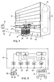
- Reference 10 in figure 1 denotes a rotary store provided with a plurality of shelves 11 having storing areas in which the shelves are hinged to endless chains 12 appropriately driven to rotate by a drive motor, to move said shelves along an annular path which extends substantially upwards in a vertical direction.
- the store 10 is operated by a computer-controlled system, schematically represented in figure 2, in which storing data may be input manually by means of a keyboard or automatically by means of a programmable on-board computer of a self-powered trolley 13, as explained hereinunder, and in which it is possible to bring any one of the shelves 11 into an appropriate loading and unloading position which is accessible to the trolley at the front of the store, as represented schematically in figure 1.
- the self-powered trolley 13 is provided with an on-board computer controlled system, schematically represented in figure 3, able to dialog with a central control unit 16 (fig. 1) to receive storage data, respectively with the computer-control system of the store 10 to provide the same with programmed storing data received by the control unit 16 through wireless connections comprising appropriate directional receiving and transmitting units 22, 23, for example of infrared ray type, provided at predetermined positions frontally along a lower band of the store 10 on the unit 16 and on one or both sides of the trolley 13 respectively, as shown.
- a central control unit 16 (fig. 1) to receive storage data, respectively with the computer-control system of the store 10 to provide the same with programmed storing data received by the control unit 16 through wireless connections comprising appropriate directional receiving and transmitting units 22, 23, for example of infrared ray type, provided at predetermined positions frontally along a lower band of the store 10 on the unit 16 and on one or both sides of the trolley 13 respectively, as shown.
- the self-powered trolley 13 which may be of any suitable type, moves along a guide path 14 defined by a built-in electromagnetic track which extends inside a work area.
- Magnetic sensors 15' are provided on the trolley 13 to sense the track 14 and if necessary magnetic plates 15 provided for indicating reference positions for the trolley 13 along the path 14, to guide the same along its path.
- dialog stations of the central control unit 16 may also be provided by means of which on-board computer 19 of the trolley 13 can communicate and dialog with the computer of a control unit 16 to receive orders and instructions which it must subsequently perform, as well as programmed storage data which must be provided to the computer 18 of the store.
- the trolley 13 on its upper surface is provided with means for gripping articles, for example in the form of a pair of extendable and retractable forks 17, suitable for projecting inside the individual loading cells or storing areas of a shelf 11, in the open condition of the store 10, as shown schematically in figure 1.
- the trolley 13 may moreover be provided with other fittings, such as for example scales for weighing the articles transported, especially useful in preparing colouring agents in textile printing.
- the scales, with the forks may if necessary be supported by the upper mobile table which can be raised and lowered automatically by a pantograph system, in itself known and not forming part of the present invention.
- the computerised control system for the store 10 comprises a CPU 18 which supervises all the control and drive functions.
- the CPU 18 must be able to dialog with a corresponding CPU 19 for guiding and controlling the self-powered trolley 13, via a suitable system for communicating and exchanging data and information.
- the CPU 18 of the store 10 through an interface 20, for example an inverter, moreover controls a motor 21 for driving the endless chains 12 and shelves 11 of the store, in a manner programmed by the same CPU.
- the control systems, both of the trolley 13 of the central unit 16 and of the store 10 are provided with wireless intercommunication units, for example of the infrared ray type, which have at least one directional transceiver 22 on the trolley 13 connected to the CPU 19 as explained hereinunder, or a corresponding transceiver on the central unit 16, as well as a plurality of directional transceivers 23 aligned in parallel along the guide path 14 on the front side of the store at each position or storing area in which the trolley 13 must stop for the loading and unloading operations.
- wireless intercommunication units for example of the infrared ray type, which have at least one directional transceiver 22 on the trolley 13 connected to the CPU 19 as explained hereinunder, or a corresponding transceiver on the central unit 16, as well as a plurality of directional transceivers 23 aligned in parallel along the guide path 14 on the front side of the store at each position or storing area in which the trolley 13 must stop for the loading and unloading operations.
- Each receiving and transmitting device 23 consists for example of a photodiode connected to the CPU 18 via an ON/OFF communication card, able to convert the two light levels of the optical transducers 23 into corresponding voltage levels and vice versa; similarly for the transducers 22 of the self-powered trolley or central unit 16.
- Figure 3 of the drawings shows a logic diagram for the computerised system controlling the self-powered trolley 13, able to dialog and exchange data and instructions with the computerised systems of control unit 16 and the store 10.
- the computerised system of the trolley comprises a CPU 19 connected to the various functional blocks of the system.
- the CPU 19 which supervises and controls all the functions of the self-powered trolley 13, communicates with the optical transducers 22 of the trolley via respective ON/OFF communication cards 25, similar to those of the store 10.
- the CPU is connected, by means of a control card 27 of the loading and unloading system of the trolley, to an interface 28, and to a supply circuit 29 and respectively an encoder or signal generator 30 which control the motor 31 for driving the forks 17.
- the trolley 13 forms part of a programmable storage and transport system, in which the trolley is totally independent from the functional point of view but integrated with the computerised control and operational system of the store 10, performing an interactive and programmable function.
- the trolley is provided with a pair of fork members 17 which telescopically slide on suitable support guides, in turn sliding in relation to a table or plane 47 of the carriage.
- the forks 17 are attached to two opposite guides 48 and 49 which can slide along a set of double wheels 50, 50' whose axes 51 are supported by a movable assembly 52 in the manner shown.
- Each movable assembly 52 is composed of two metal sections crossed by the axes 51 of the wheels 50, 50'; the wheels 50' in turn slide along opposite guides 53, 54 attached by means of a plate 55 to the table 47 of the trolley.
- a link chain 56 is attached with which cogged wheels 57 engage, the latter being connected by means a coupling shafts 58 and a transmission 59 to the drive motor 31.
- each movable assembly 52 for guiding the forks drives the movement of the latter by means of cogged wheels 60 and an endless chain 61 which is attached on one side to the forks 17 and on the other side to the table 47 in central positions to the chains themselves.
Landscapes
- Engineering & Computer Science (AREA)
- Mechanical Engineering (AREA)
- Warehouses Or Storage Devices (AREA)
- Forklifts And Lifting Vehicles (AREA)
Claims (5)
- Automatisiertes System zum Transportieren, Laden, Entladen und Lagern von Gegenständen in einem Arbeitsbereich, insbesondere zum Vorbereiten von Färbemitteln in der Textilindustrie, wobei das System in Kombination enthält:eine computergesteuerte Lagereinrichtung (10) zum Lagern von Gegenständen, wobei die Lagereinrichtung (10) Fachelemente (11) enthält, die längs eines vertikalen Wegs beweglich unterstützt sind, wobei jedes der Fachelemente (11) nebeneinander angeordnete Lagerbereiche definiert;eine elektromagnetische Spur, die im Arbeitsbereich einen Fahrweg (14) definiert, wobei die Spur einen zur Lagereinrichtung (10) parallel angeordneten Abschnitt besitzt;wenigstens ein computergesteuertes, batteriebetriebenes Fahrzeug (13) zum Transportieren der Gegenstände längs des Fahrwegs, wobei das batteriebetriebene Fahrzeug eine Greifeinrichtung (17) zum Laden und Entladen von Gegenständen in die Lagerbereiche bzw. aus den Lagerbereichen eines ausgewählten der Fachelemente (11) besitzt und einen programmierbaren Bordcomputer (19) enthält;eine zentrale Steuereinheit (16), die mit Fahrinformationen für das batteriebetriebene Fahrzeug (13) sowie mit Lagerdaten zum Lagern und Entnehmen von Gegenständen in den Lagerbereichen bzw. aus den Lagerbereichen der Fachelemente (11),ein optisches, drahtloses Kommunikationssystem (22; 25; 23, 24) zum Übertragen von Lagerdaten und Fahrinformationen zwischen der Hauptsteuereinheit (16) und dem Bordcomputer 19 des batteriebetriebenen Fahrzeugs (13) und zum Übertragen von Lagerdaten zwischen dem Bordcomputer (19) des Fahrzeugs (13) und dem Computer (18) der Lagereinrichtung (10), wobei das optische Kommunikationssystem Lichtsende- und Lichterfassungsvorrichtungen an der zentralen Steuereinheit (16), am batteriebetriebenen Fahrzeug (13) sowie an Haltepositionen (23) für das batteriebetriebene Fahrzeug (13), die auf die Lagerbereiche der Fachelemente (11) längs des parallel zur Lagereinrichtung (10) angeordneten Abschnitts des Fahrwegs ausgerichtet sind, umfaßt;wobei der Bordcomputer (19) des batteriebetriebenen Fahrzeugs (13) durch die Hauptsteuereinheit (16) mit den Fahrinformationen und den Lagerdaten für ein ausgewähltes Fachelement (11) programmierbar ist;wobei der Computer (18) der Lagereinrichtung (10) durch den Bordcomputer (19) des batteriebetriebenen Fahrzeugs (13) mit den Lagerdaten des ausgewählten der Fachelemente (11) der Lagereinrichtung (10) programmierbar ist.
- Automatisiertes System nach Anspruch 1, dadurch gekennzeichnet, daß das batteriebetriebene Fahrzeug (13) eine Steuereinrichtung (29, 30) für die Greifeinrichtung (17) enthält, die mit dem Bordcomputer (19) des batteriebetriebenen Fahrzeugs (13) in der Weise funktional verbunden ist, daß sie eine programmierte Bewegung der Greifeinrichtung (17) zwischen eingefahrenen und ausgefahrenen Stellungen in bezug auf den ausgewählten Lagerbereich eines Fachelements (11) der Lagereinrichtung (10) steuert.
- Automatisiertes System nach Anspruch 2, dadurch gekennzeichnet, daß das batteriebetriebene Fahrzeug (13) eine Skaleneinheit zum Wiegen der von der Greifeinrichtung (17) gegriffenen Gegenstände enthält, die so angeschlossen ist, daß sie dem Bordcomputer (19) des batteriebetriebenen Fahrzeugs (13) die Gewichtsdaten der von der Greifeinrichtung (17) gegriffenen Gegenstände liefert.
- Automatisiertes System nach Anspruch 2, dadurch gekennzeichnet, daß die Greifeinrichtung (17) versehen ist mit teleskopartig ausfahrenden Gabelelementen (17), wovon jedes an einer Führungsbaueinheit (52) gleitend beweglich ist, wobei die Führungsbaueinheit (52) am batteriebetriebenen Fahrzeug (13) durch gegenüberliegende Führungselemente (53, 54) gleitend unterstützt ist, sowie mit einer Antriebseinrichtung (58, 61), die zwischen jedem der Gabelelemente (17) und der Führungsbaueinheit (52) vorgesehen ist.
- Automatisiertes System nach Anspruch 4, dadurch gekennzeichnet, daß die Antriebseinrichtung (58, 61) ein Zahnstangenelement (56, 47) zwischen jeder Führungsbaueinheit (52) der Gabelelemente (17), einen Antriebsmotor (31) und ein flexibles, ringförmiges Kraftübertragungselement (61) enthält, wobei sich das flexible, ringförmige Kraftübertragungselement (61) parallel zur Führungsbaueinheit (52) erstreckt, um die Gabelelemente (17) zu verbinden, und Zahnräder (60) an der Führungsbaueinheit (52) miteinander in Eingriff bringt.
Applications Claiming Priority (2)
| Application Number | Priority Date | Filing Date | Title |
|---|---|---|---|
| ITMI921410A IT1258954B (it) | 1992-06-05 | 1992-06-05 | Sistema per prelevare oggetti da un magazzino rotante mediante un carrello semovente programmato per trasportarli in un'area di lavoro |
| ITMI921410 | 1992-06-05 |
Publications (2)
| Publication Number | Publication Date |
|---|---|
| EP0572967A1 EP0572967A1 (de) | 1993-12-08 |
| EP0572967B1 true EP0572967B1 (de) | 1997-08-13 |
Family
ID=11363472
Family Applications (1)
| Application Number | Title | Priority Date | Filing Date |
|---|---|---|---|
| EP93108773A Expired - Lifetime EP0572967B1 (de) | 1992-06-05 | 1993-06-01 | Drahtloses, automatisiertes und rechnergesteuertes Lager- und Transportsystem |
Country Status (6)
| Country | Link |
|---|---|
| US (1) | US5409342A (de) |
| EP (1) | EP0572967B1 (de) |
| AT (1) | ATE156769T1 (de) |
| DE (1) | DE69313020T2 (de) |
| ES (1) | ES2105007T3 (de) |
| IT (1) | IT1258954B (de) |
Families Citing this family (15)
| Publication number | Priority date | Publication date | Assignee | Title |
|---|---|---|---|---|
| FR2730980B1 (fr) * | 1995-02-27 | 1997-04-04 | Oreal | Procede de preparation de commandes, chariot de collecte pour la mise en oeuvre de ce procede et systeme de preparation de commandes |
| US5980185A (en) * | 1997-07-30 | 1999-11-09 | Vita Auto Stack, Inc. | Vehicle parking structure |
| JPH1159829A (ja) * | 1997-08-08 | 1999-03-02 | Mitsubishi Electric Corp | 半導体ウェハカセット搬送装置、半導体ウェハカセット搬送装置で用いられるストッカ、ならびに半導体ウェハカセット搬送装置で用いられるストッカ入庫作業制御方法、ストッカ出庫作業制御方法、自動搬送車制御方法、およびストッカ在庫照合方法 |
| DE10050097A1 (de) * | 2000-10-09 | 2002-06-20 | Roland Man Druckmasch | Gummizylinderhülse für Offsetdruckmaschinen |
| US6584375B2 (en) * | 2001-05-04 | 2003-06-24 | Intellibot, Llc | System for a retail environment |
| WO2004087558A2 (de) * | 2003-04-04 | 2004-10-14 | Swisslog Ag | Verfahren zur übernahme und/oder übergabe und zum transport von waren |
| US7147154B2 (en) * | 2003-04-29 | 2006-12-12 | International Business Machines Corporation | Method and system for assisting a shopper in navigating through a store |
| US20060051190A1 (en) * | 2004-09-08 | 2006-03-09 | Kazuhiro Taguchi | Article storage system |
| CN100464263C (zh) * | 2004-10-18 | 2009-02-25 | 徐益忠 | 无线控制密集柜的移动系统及其装置 |
| DE102007029308A1 (de) * | 2007-06-22 | 2008-12-24 | Bellheimer Metallwerk Gmbh | Automatisches Handling von Mehrfachlagergutträgern |
| FR3009880B1 (fr) * | 2013-08-20 | 2017-07-14 | Globe Interfin S A | Systeme de commande en ligne et de livraison |
| WO2019090196A1 (en) | 2017-11-03 | 2019-05-09 | Box Bot Inc. | Package receiving and delivery system |
| CA3083095A1 (en) * | 2017-11-21 | 2019-05-31 | Fulfil Solutions, Inc. | Product handling and packaging system |
| IT202000011974A1 (it) * | 2020-05-21 | 2021-11-21 | Immobiliare Metalprogetti S R L | Magazzino automatizzato |
| CN118025699A (zh) * | 2024-03-28 | 2024-05-14 | 北京京东乾石科技有限公司 | 供包分播机构、系统、装置、计算机可读存储介质及方法 |
Family Cites Families (23)
| Publication number | Priority date | Publication date | Assignee | Title |
|---|---|---|---|---|
| FR1394414A (fr) * | 1964-04-14 | 1965-04-02 | Appareil élévateur pour l'enfournement des pâtons à pain de boulangerie | |
| US3796327A (en) * | 1972-07-14 | 1974-03-12 | R Meyer | Manufacturing system |
| US4388033A (en) * | 1981-03-16 | 1983-06-14 | Eaton Corporation | Shuttle assembly |
| JPS57194863A (en) * | 1981-05-24 | 1982-11-30 | Murata Mach Ltd | Automatic workpiece exchanger |
| DE3219459C2 (de) * | 1981-05-19 | 1987-01-15 | Murata Kikai K.K., Kyoto | Automatische Förderanlage zum Transportieren einer Normpalette |
| JPS57194861A (en) * | 1981-05-25 | 1982-11-30 | Murata Mach Ltd | Automatic transfer system of workpiece in machine shop |
| EP0110547A1 (de) * | 1982-11-05 | 1984-06-13 | Plessey Overseas Limited | Förder- und Speichersystem |
| CA1224425A (en) * | 1983-05-31 | 1987-07-21 | Keith E. Hanford | Warehouse system with pan extractor mechanism |
| JPS60262701A (ja) * | 1984-06-11 | 1985-12-26 | Daifuku Co Ltd | 移動棚からの小物品ピツキングシステム |
| US4801236A (en) * | 1985-04-06 | 1989-01-31 | Karl Mengele & Sohne Gmbh & Co. | Mechanical inventory storage and delivery cabinet |
| IT1187368B (it) * | 1985-05-10 | 1987-12-23 | Gd Spa | Sistema di alimentazione automatizzata di materiale di produzione e/o confezionamento da un magazzino a linee di lavoro |
| US4691385A (en) * | 1985-09-05 | 1987-09-01 | Caterpillar Industrial Inc. | Optical communication apparatus for a vehicle |
| SE449989B (sv) * | 1985-10-15 | 1987-06-01 | Mecanum Ab | Sett att vid fordon med en lyftanordning kompensera avvikelser hos leget pa last pa lyftanordningen i forhallande till fordonsunderredet |
| IT1186117B (it) * | 1985-11-29 | 1987-11-18 | Snia Fibre | Struttura di magazzino per bobine di filato |
| JPS62251125A (ja) * | 1986-04-25 | 1987-10-31 | Bridgestone Corp | 成型・加硫工程間の生タイヤ自動搬送設備 |
| JPH0717244B2 (ja) * | 1986-04-30 | 1995-03-01 | 富士電機株式会社 | 集品装置 |
| FR2599017B1 (fr) * | 1986-05-26 | 1988-09-02 | Productique Cie Gle | Equipement pour appareil de manutention de charges permettant la sortie d'une charge du cote oppose a sa prehension. |
| DE3632448A1 (de) * | 1986-09-24 | 1988-04-07 | Pharma Rechenzentrum Gmbh | Verfahren zur rechnergesteuerten zusammenstellung von verschiedenen artikeln von auftraegen und vorrichtung zur durchfuehrung des verfahrens |
| WO1988005018A1 (fr) * | 1986-12-25 | 1988-07-14 | Kabushikikaisha Itoki Kosakusho | Dispositif automatique de stockage et recuperation d'articles |
| US5113349A (en) * | 1988-03-26 | 1992-05-12 | Fuji Electric Co. Ltd. | Method and system for storing/removing and distributing articles of manufacture |
| JPH02152898A (ja) * | 1988-12-06 | 1990-06-12 | Komatsu Forklift Co Ltd | 荷役車両における在庫管理方法 |
| JPH0747403B2 (ja) * | 1990-05-22 | 1995-05-24 | インベストロニカ・ソシエダッド・アノニマ | プログラム制御による箱、コンテナ等の操作・移送装置 |
| JPH0542913A (ja) * | 1991-07-26 | 1993-02-23 | Ishida Scales Mfg Co Ltd | 包装装置 |
-
1992
- 1992-06-05 IT ITMI921410A patent/IT1258954B/it active IP Right Grant
-
1993
- 1993-06-01 DE DE69313020T patent/DE69313020T2/de not_active Expired - Fee Related
- 1993-06-01 EP EP93108773A patent/EP0572967B1/de not_active Expired - Lifetime
- 1993-06-01 AT AT93108773T patent/ATE156769T1/de not_active IP Right Cessation
- 1993-06-01 ES ES93108773T patent/ES2105007T3/es not_active Expired - Lifetime
- 1993-06-02 US US08/071,386 patent/US5409342A/en not_active Expired - Fee Related
Also Published As
| Publication number | Publication date |
|---|---|
| EP0572967A1 (de) | 1993-12-08 |
| IT1258954B (it) | 1996-03-11 |
| US5409342A (en) | 1995-04-25 |
| ES2105007T3 (es) | 1997-10-16 |
| DE69313020D1 (de) | 1997-09-18 |
| DE69313020T2 (de) | 1997-12-04 |
| ITMI921410A0 (it) | 1992-06-05 |
| ATE156769T1 (de) | 1997-08-15 |
| ITMI921410A1 (it) | 1993-12-05 |
Similar Documents
| Publication | Publication Date | Title |
|---|---|---|
| US5409342A (en) | Wireless automated computer-controlled storing and articles transporting system | |
| US11034532B2 (en) | Picking device for picking from a storage container into an order container, and corresponding method | |
| CN111278753B (zh) | 用于处理物体的包括移动矩阵载体系统的移动系统和方法 | |
| US5211523A (en) | Assembly for programmed controlled handling and transporting of boxes, containers or the like | |
| JP2021091404A (ja) | 搬送ロボット | |
| US5226782A (en) | Automatic storage and retrieval system | |
| US4492504A (en) | Materials handling system | |
| CN105636883B (zh) | 自动货架系统 | |
| US4664590A (en) | Transportable robot system | |
| US3978995A (en) | Mobile tier picking apparatus for a warehousing system | |
| US6450318B1 (en) | Overhead monorail system | |
| US3866767A (en) | Mobile tier picking apparatus for a warehousing system | |
| CN211944871U (zh) | 一种智能仓储系统 | |
| KR20080022040A (ko) | 물품 수납 설비와 그 제어 방법 | |
| JP3436334B2 (ja) | 物品搬送設備 | |
| JP5170536B2 (ja) | 物品処理設備 | |
| CN102233527A (zh) | 工序间柔性自动搬送系统 | |
| US3093252A (en) | Automatic warehouse | |
| CN215709078U (zh) | 堆垛机、运输系统及仓储系统 | |
| JP2003267518A (ja) | 物流設備 | |
| CN114084849A (zh) | 一种料箱搬运机器人 | |
| FI89699B (fi) | Anordning foer hantering av pappersrullar i en anlaeggning, saosom tryckeri | |
| CN113619988A (zh) | 一种箱式物流中转站控制系统及其控制方法 | |
| CN111451156A (zh) | 一种分拣传输系统及分拣传输方法 | |
| JPH09315520A (ja) | 物品保管棚用の物品搬送装置 |
Legal Events
| Date | Code | Title | Description |
|---|---|---|---|
| PUAI | Public reference made under article 153(3) epc to a published international application that has entered the european phase |
Free format text: ORIGINAL CODE: 0009012 |
|
| AK | Designated contracting states |
Kind code of ref document: A1 Designated state(s): AT BE CH DE ES FR GB LI NL |
|
| 17P | Request for examination filed |
Effective date: 19940428 |
|
| 17Q | First examination report despatched |
Effective date: 19950601 |
|
| GRAG | Despatch of communication of intention to grant |
Free format text: ORIGINAL CODE: EPIDOS AGRA |
|
| RAP1 | Party data changed (applicant data changed or rights of an application transferred) |
Owner name: INDUSTRIAL AUTOMATION SYSTEM S.R.L. |
|
| RAP3 | Party data changed (applicant data changed or rights of an application transferred) |
Owner name: INDUSTRIAL AUTOMATION SYSTEM S.R.L. |
|
| GRAH | Despatch of communication of intention to grant a patent |
Free format text: ORIGINAL CODE: EPIDOS IGRA |
|
| GRAH | Despatch of communication of intention to grant a patent |
Free format text: ORIGINAL CODE: EPIDOS IGRA |
|
| GRAA | (expected) grant |
Free format text: ORIGINAL CODE: 0009210 |
|
| AK | Designated contracting states |
Kind code of ref document: B1 Designated state(s): AT BE CH DE ES FR GB LI NL |
|
| PG25 | Lapsed in a contracting state [announced via postgrant information from national office to epo] |
Ref country code: LI Free format text: LAPSE BECAUSE OF FAILURE TO SUBMIT A TRANSLATION OF THE DESCRIPTION OR TO PAY THE FEE WITHIN THE PRESCRIBED TIME-LIMIT Effective date: 19970813 Ref country code: CH Free format text: LAPSE BECAUSE OF FAILURE TO SUBMIT A TRANSLATION OF THE DESCRIPTION OR TO PAY THE FEE WITHIN THE PRESCRIBED TIME-LIMIT Effective date: 19970813 Ref country code: AT Effective date: 19970813 |
|
| REF | Corresponds to: |
Ref document number: 156769 Country of ref document: AT Date of ref document: 19970815 Kind code of ref document: T |
|
| REG | Reference to a national code |
Ref country code: CH Ref legal event code: EP |
|
| ET | Fr: translation filed | ||
| REF | Corresponds to: |
Ref document number: 69313020 Country of ref document: DE Date of ref document: 19970918 |
|
| REG | Reference to a national code |
Ref country code: ES Ref legal event code: FG2A Ref document number: 2105007 Country of ref document: ES Kind code of ref document: T3 |
|
| REG | Reference to a national code |
Ref country code: CH Ref legal event code: PL |
|
| PG25 | Lapsed in a contracting state [announced via postgrant information from national office to epo] |
Ref country code: GB Free format text: LAPSE BECAUSE OF NON-PAYMENT OF DUE FEES Effective date: 19980601 |
|
| PLBE | No opposition filed within time limit |
Free format text: ORIGINAL CODE: 0009261 |
|
| STAA | Information on the status of an ep patent application or granted ep patent |
Free format text: STATUS: NO OPPOSITION FILED WITHIN TIME LIMIT |
|
| PG25 | Lapsed in a contracting state [announced via postgrant information from national office to epo] |
Ref country code: BE Free format text: LAPSE BECAUSE OF NON-PAYMENT OF DUE FEES Effective date: 19980630 |
|
| 26N | No opposition filed | ||
| BERE | Be: lapsed |
Owner name: INDUSTRIAL AUTOMATION SYSTEM S.R.L. Effective date: 19980630 |
|
| GBPC | Gb: european patent ceased through non-payment of renewal fee |
Effective date: 19980601 |
|
| PGFP | Annual fee paid to national office [announced via postgrant information from national office to epo] |
Ref country code: FR Payment date: 19990526 Year of fee payment: 7 |
|
| PGFP | Annual fee paid to national office [announced via postgrant information from national office to epo] |
Ref country code: ES Payment date: 19990616 Year of fee payment: 7 |
|
| PGFP | Annual fee paid to national office [announced via postgrant information from national office to epo] |
Ref country code: NL Payment date: 19990630 Year of fee payment: 7 |
|
| PGFP | Annual fee paid to national office [announced via postgrant information from national office to epo] |
Ref country code: DE Payment date: 19990728 Year of fee payment: 7 |
|
| PG25 | Lapsed in a contracting state [announced via postgrant information from national office to epo] |
Ref country code: ES Free format text: THE PATENT HAS BEEN ANNULLED BY A DECISION OF A NATIONAL AUTHORITY Effective date: 20000602 |
|
| PG25 | Lapsed in a contracting state [announced via postgrant information from national office to epo] |
Ref country code: NL Free format text: LAPSE BECAUSE OF NON-PAYMENT OF DUE FEES Effective date: 20010101 |
|
| PG25 | Lapsed in a contracting state [announced via postgrant information from national office to epo] |
Ref country code: FR Free format text: LAPSE BECAUSE OF NON-PAYMENT OF DUE FEES Effective date: 20010228 |
|
| NLV4 | Nl: lapsed or anulled due to non-payment of the annual fee |
Effective date: 20010101 |
|
| REG | Reference to a national code |
Ref country code: FR Ref legal event code: ST |
|
| PG25 | Lapsed in a contracting state [announced via postgrant information from national office to epo] |
Ref country code: DE Free format text: LAPSE BECAUSE OF NON-PAYMENT OF DUE FEES Effective date: 20010403 |
|
| REG | Reference to a national code |
Ref country code: ES Ref legal event code: FD2A Effective date: 20020204 |