EP0573028A2 - Chambre de combustion, en particulier pour la régénération d'un filtre à particules dans un dispositif d'échappement d'un véhicule à moteur - Google Patents
Chambre de combustion, en particulier pour la régénération d'un filtre à particules dans un dispositif d'échappement d'un véhicule à moteur Download PDFInfo
- Publication number
- EP0573028A2 EP0573028A2 EP93108911A EP93108911A EP0573028A2 EP 0573028 A2 EP0573028 A2 EP 0573028A2 EP 93108911 A EP93108911 A EP 93108911A EP 93108911 A EP93108911 A EP 93108911A EP 0573028 A2 EP0573028 A2 EP 0573028A2
- Authority
- EP
- European Patent Office
- Prior art keywords
- combustion chamber
- supply device
- combustion
- fuel
- jacket
- Prior art date
- Legal status (The legal status is an assumption and is not a legal conclusion. Google has not performed a legal analysis and makes no representation as to the accuracy of the status listed.)
- Granted
Links
Images

Classifications
-
- F—MECHANICAL ENGINEERING; LIGHTING; HEATING; WEAPONS; BLASTING
- F01—MACHINES OR ENGINES IN GENERAL; ENGINE PLANTS IN GENERAL; STEAM ENGINES
- F01N—GAS-FLOW SILENCERS OR EXHAUST APPARATUS FOR MACHINES OR ENGINES IN GENERAL; GAS-FLOW SILENCERS OR EXHAUST APPARATUS FOR INTERNAL-COMBUSTION ENGINES
- F01N3/00—Exhaust or silencing apparatus having means for purifying, rendering innocuous, or otherwise treating exhaust
- F01N3/02—Exhaust or silencing apparatus having means for purifying, rendering innocuous, or otherwise treating exhaust for cooling, or for removing solid constituents of, exhaust
- F01N3/021—Exhaust or silencing apparatus having means for purifying, rendering innocuous, or otherwise treating exhaust for cooling, or for removing solid constituents of, exhaust by means of filters
- F01N3/023—Exhaust or silencing apparatus having means for purifying, rendering innocuous, or otherwise treating exhaust for cooling, or for removing solid constituents of, exhaust by means of filters using means for regenerating the filters, e.g. by burning trapped particles
- F01N3/025—Exhaust or silencing apparatus having means for purifying, rendering innocuous, or otherwise treating exhaust for cooling, or for removing solid constituents of, exhaust by means of filters using means for regenerating the filters, e.g. by burning trapped particles using fuel burner or by adding fuel to exhaust
-
- F—MECHANICAL ENGINEERING; LIGHTING; HEATING; WEAPONS; BLASTING
- F23—COMBUSTION APPARATUS; COMBUSTION PROCESSES
- F23C—METHODS OR APPARATUS FOR COMBUSTION USING FLUID FUEL OR SOLID FUEL SUSPENDED IN A CARRIER GAS OR AIR
- F23C7/00—Combustion apparatus characterised by arrangements for air supply
- F23C7/002—Combustion apparatus characterised by arrangements for air supply the air being submitted to a rotary or spinning motion
-
- F—MECHANICAL ENGINEERING; LIGHTING; HEATING; WEAPONS; BLASTING
- F23—COMBUSTION APPARATUS; COMBUSTION PROCESSES
- F23D—BURNERS
- F23D11/00—Burners using a direct spraying action of liquid droplets or vaporised liquid into the combustion space
- F23D11/36—Details
- F23D11/42—Starting devices
Definitions
- the present invention relates to a combustion chamber, in particular for a burner used to regenerate a particle filter in a motor vehicle exhaust system.
- a safe starting behavior of the combustion chamber has proven to be essential so that the burner operated by the combustion chamber can regenerate the filter in good time by burning the soot particles deposited in a soot filter, for example to prevent a reduction in performance of the motor vehicle due to an added soot filter.
- combustion chambers previously used in the burners mentioned have not always proven to be reliable with regard to their starting properties. In addition, increasing combustion chamber efficiency to reduce fuel consumption is also desirable.
- the present invention is therefore based on the object of creating a combustion chamber which is distinguished by good starting properties and a high combustion chamber efficiency.
- a nozzle is provided in the combustion chamber base, which serves on the one hand for receiving an electrical ignition device and on the other hand opens into a first fuel supply device and a first combustion air supply device.
- the arrangement of the nozzle in the combustion chamber floor ensures that both the fuel introduced into the nozzle and the combustion air flow axially outward from the nozzle into the combustion chamber interior. Due to the axially oriented, low-turbulence flow of the ignitable gas mixture introduced in the nozzle area, its flammability has proven to be particularly reliable.
- the special design of the combustion air supply device in the combustion chamber jacket ensures that an at least partially tangentially oriented combustion air flow hits and swirls the fuel quantity introduced through the combustion chamber jacket. Due to the swirling, a particularly homogeneous formation of the mixture is achieved, which is easily and uniformly ignitable by the pilot flame generated by the ignition mixture formed in the nozzle.
- the homogeneous formation of the main mixture formed by the fuel and the combustion air which are supplied through the combustion chamber jacket not only ensures rapid and uniform flammability, but also high combustion chamber efficiency.
- the fuel supply device can be designed as a fuel wall application device, in which the fuel is fed into the combustion chamber by means of supply openings in the combustion chamber jacket, through which the combustion chamber inner wall can be wetted with fuel.
- the main mixture is formed in the combustion chamber essentially by evaporation of the fuel applied to the inner wall of the combustion chamber. It proves to be expedient to provide the corresponding feed openings as close as possible to the bottom of the combustion chamber so that the pilot flame formed by the ignition mixture in the nozzle can contribute to the evaporation of the fuel. As a result, the evaporation can take place essentially without prior heating of the combustion chamber.
- Another possibility of supplying fuel through the combustion chamber jacket is to design the fuel supply device as a fuel space introduction device, by means of which it is possible to introduce the fuel into the combustion chamber interior in a directed manner.
- the introduction of the fuel this takes place at a distance from the inner wall of the combustion chamber, since the fuel can thus be introduced directly into the highly turbulent zone of the combustion chamber formed by the inner wall of the combustion chamber through an essentially laminar or less turbulent edge zone. This allows good mixing to be achieved as quickly as possible.
- the combustion air supply device in the combustion chamber casing is formed by an annular combustion chamber casing element which is provided with at least one tangentially oriented supply opening.
- the combustion chamber jacket element can be designed as an integral part of the combustion chamber jacket or also independently. In the latter case, a modular construction of the combustion chamber according to the invention is possible, so that, for example, a conventional combustion chamber element can be supplemented with the combustion chamber jacket element to form a combustion chamber according to the invention.
- the second or a further combustion air supply device from an annular combustion chamber jacket element which has at least one tangential into the combustion chamber jacket element is provided, the second or a further fuel supply device opens into the supply pipe. This makes it possible to form the combustion mixture or at least part of the combustion mixture outside the combustion chamber jacket.
- the feed pipe of the combustion air supply device is provided with at least two feed openings opening into the combustion chamber interior at a distance from one another, so that an inflow of combustion air can be achieved at different inflow angles.
- the result of this is a particularly good mixing of the air flows that meet at different angles in the combustion chamber or a mixing of fuel gas already in the combustion chamber by means of the air flows that strike the fuel gas.
- the combustion air flow directed through the supply pipe to the combustion chamber interior is divided into a pure combustion air flow which, viewed in the flow direction, enters the combustion chamber interior in front of the fuel supply device, and a mixed combustion stream which, viewed in the flow direction, enters the combustion chamber interior behind the fuel supply device.
- the fuel feed device in Seen downstream flow direction an ignition device is provided.
- ignition of the combustion mixture in the feed pipe is possible outside the actual combustion chamber interior.
- the ignition device in the feed pipe can also be operated independently of the ignition device arranged in the combustion chamber bottom, and consequently a combustion chamber according to the invention can also be equipped without the ignition device in the combustion chamber floor, but only with the ignition device in the feed pipe.
- impact devices can be provided in the area of the combustion chamber jacket element, which lead to a throttling of the entry velocity of the air flow entering through the feed pipe and to an increase in turbulence formation in the area of the incoming combustion air flow. Both effects help to achieve a better mixture formation in the combustion chamber interior. Furthermore, the arrangement of the impact devices at the designated point contributes to the fact that flow noises are at least partially suppressed, in particular as a result of the throttling of the entry speed.
- baffle devices are arranged distributed over the inner circumference of the combustion chamber casing element, since this arrangement allows the baffle devices to be particularly effective.
- the efficiency of the combustion chamber according to the invention can be increased even further by providing a diffuser at the downstream end of the combustion chamber.
- the diffuser is with a additional fuel supply device, so that it is possible to use combustion air that has entered through the combustion air supply device in the combustion chamber jacket without being consumed for the combustion of the fuel supplied through the combustion chamber jacket in the diffuser for a kind of afterburning.
- By connecting the diffuser in total stoichiometric combustion can thus be achieved even in a combustion chamber designed as a vortex combustion chamber in the present case.
- a baffle device can be arranged opposite the inlet opening of the diffuser on the flow side as a measure to increase turbulence.
- An inlet screen can be arranged upstream of the combustion air supply device in the combustion chamber jacket.
- an outlet orifice can be provided downstream of the combustion air supply device and at the same time forms the inlet opening of the diffuser.
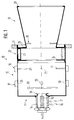
- combustion chamber 10 with a combustion chamber base 11, a combustion chamber jacket 12 and a diffuser 13 arranged opposite the combustion chamber base 11, which in the exemplary embodiment shown here forms the flow-side closure of the combustion chamber 10.
- a nozzle 14 which serves to receive an electrical ignition device 15 and into which a first fuel supply device 16 and a first combustion air supply device 17 open.
- the fuel supply device 16 and the combustion air supply device 17 open into the connecting piece 14 arranged transversely to the longitudinal axis of the combustion chamber 10.
- the fuel supply device 16 and the combustion air supply device 17 it is of course also possible for the fuel supply device 16 and the combustion air supply device 17 to be introduced into the connection piece parallel to the longitudinal axis of the combustion chamber 10, or for one of the two supply devices to open into the connection piece 14 transversely to the other.
- a further fuel supply device 18 or 19 is arranged on the combustion chamber jacket 12, which are shown here side by side in the drawing, but can also be provided individually, that is to say independently of one another, on the combustion chamber jacket 12.
- the fuel supply device 18 is designed as a fuel wall application device, in which the fuel is arranged through one or more feed openings 20 arranged around the circumference for wetting the combustion chamber inner wall.
- the fuel supply device 19 is designed as a fuel space introduction device, in which supply nozzles 21 projecting into the combustion chamber 10 are distributed over the circumference, through which the fuel can be introduced into the combustion chamber, for example by spraying.
- combustion air supply device 22 is provided in the combustion chamber casing 12.
- the combustion air supply device 22 has a plurality of supply openings 23 which are distributed over the circumference of the combustion chamber jacket and through which combustion air can be introduced into the combustion chamber 10 essentially tangentially.
- the combustion air supply device 22 is designed as a combustion chamber jacket element which is provided with an inlet panel 24 on or in the combustion chamber jacket 12.
- the downstream end of the combustion chamber 10 is formed by the diffuser 13, the inlet opening of which is designed as an outlet diaphragm 25, and which is inserted with it into the combustion chamber jacket 12 or the combustion chamber jacket element 22.
- the diffuser 13 is provided in the region of its inlet opening, that is to say the outlet diaphragm 25, with a further fuel feed device 26, here in the manner of the fuel feed device 19.
- the combustion chamber 10 is inserted into a receiving flange 27 of the burner housing.
- turbulence edge 28 at the junction of the nozzle 14 into the combustion chamber base 11 a turbulence edge 29 at the outlet of the diffuser 13 and an impact disk 30 inside the combustion chamber 10 provided.
- the baffle plate 30 becomes red-hot and therefore acts as a glow or ignition element.
- an ignitable mixture can be formed in the nozzle space which, after ignition by the ignition device 15, enables the creation of a pilot flame. Since the ignition mixture is ignited in the nozzle chamber within a flow-restricted area, reliable ignition of the ignition mixture is independent of the flow rates supplied by the combustion air supply device 22 in the combustion chamber jacket 12 Main combustion air possible.
- the main combustion air entered tangentially into the combustion chamber 10 through the supply openings 23 forms, together with the main fuel fraction input through the fuel supply device 18 and / or 19, the main mixture which can be ignited by the pilot flame formed by means of the ignition mixture.
- the diffuser 13 downstream of the combustion air supply device 22 additional fuel is supplied by the fuel supply device 26, so that essentially all of the air introduced into the combustion chamber by the combustion air supply device 22 is used for combustion.
- FIG. 2 shows, in an alternative embodiment, a second combustion air supply device designed as a combustion chamber jacket element 31, into which a supply pipe 32 opens tangentially.
- the feed pipe 32 is provided in its mouth-side end area 33 with a fuel feed device 34 which opens laterally into the end area 33.
- two feed openings 35, 36 opening into the combustion chamber interior are located downstream of the fuel supply device 34.
- the arrows 37 and 38 shown in FIG. 2 are intended to indicate the directions of those entering the combustion chamber interior from the feed openings 35 and 36 To indicate currents. It is evident from this illustration that particularly good mixing is achieved by the flows entering the combustion chamber interior at different entry angles.
- both supply openings 35 and 36 are located downstream of the fuel supply device 34.
- An ignitable mixture therefore enters the combustion chamber interior through both supply openings.
- an ignition device (not shown in FIG. 2) can be provided downstream of the fuel supply device 34.
- impact devices in the form of webs 39 projecting into the combustion chamber interior are provided on the inside of the combustion chamber jacket element 31.
- the webs 39 cause a drop in speed and a swirling of the flow entering through the feed opening 36.
- the webs 39 are only distributed over a quarter circumference of the combustion chamber jacket element 31. However, a more extensive one, such as an arrangement over the entire circumference, can also be useful.
Landscapes
- Engineering & Computer Science (AREA)
- Chemical & Material Sciences (AREA)
- Combustion & Propulsion (AREA)
- Mechanical Engineering (AREA)
- General Engineering & Computer Science (AREA)
- Processes For Solid Components From Exhaust (AREA)
- Fluidized-Bed Combustion And Resonant Combustion (AREA)
- Pressure-Spray And Ultrasonic-Wave- Spray Burners (AREA)
Applications Claiming Priority (2)
| Application Number | Priority Date | Filing Date | Title |
|---|---|---|---|
| DE4218629 | 1992-06-05 | ||
| DE4218629A DE4218629A1 (de) | 1992-06-05 | 1992-06-05 | Brennkammer, insbesondere für die Partikelfilterregenerierung in einer Kraftfahrzeug-Abgasanlage |
Publications (3)
| Publication Number | Publication Date |
|---|---|
| EP0573028A2 true EP0573028A2 (fr) | 1993-12-08 |
| EP0573028A3 EP0573028A3 (fr) | 1994-03-09 |
| EP0573028B1 EP0573028B1 (fr) | 1996-12-27 |
Family
ID=6460500
Family Applications (1)
| Application Number | Title | Priority Date | Filing Date |
|---|---|---|---|
| EP93108911A Expired - Lifetime EP0573028B1 (fr) | 1992-06-05 | 1993-06-03 | Chambre de combustion, en particulier pour la régénération d'un filtre à particules dans un dispositif d'échappement d'un véhicule à moteur |
Country Status (3)
| Country | Link |
|---|---|
| EP (1) | EP0573028B1 (fr) |
| AT (1) | ATE146869T1 (fr) |
| DE (2) | DE4218629A1 (fr) |
Cited By (1)
| Publication number | Priority date | Publication date | Assignee | Title |
|---|---|---|---|---|
| EP0631039A1 (fr) * | 1993-06-09 | 1994-12-28 | Firma J. Eberspächer | Brûleur pour réchauffer rapidement et de façon indépendante du moteur un catalyseur d'échappement |
Families Citing this family (4)
| Publication number | Priority date | Publication date | Assignee | Title |
|---|---|---|---|---|
| DE19812561C5 (de) * | 1998-03-21 | 2006-02-16 | J. Eberspächer GmbH & Co. KG | Mit Flüssigbrennstoff betriebenes Heizgerät, insbesondere für Kraftfahrzeuge |
| DE10221495B4 (de) * | 2002-05-14 | 2004-03-11 | Webasto Thermosysteme International Gmbh | Brenner für ein Heizgerät |
| DE10227810B4 (de) * | 2002-06-21 | 2004-08-26 | Webasto Thermosysteme International Gmbh | Brenner für ein Heizgerät mit einer Prallscheibe |
| DE102016116687B4 (de) | 2016-09-07 | 2019-12-05 | Eberspächer Climate Control Systems GmbH & Co. KG | Brennkammerbaugruppe für einen Verdampferbrenner |
Family Cites Families (5)
| Publication number | Priority date | Publication date | Assignee | Title |
|---|---|---|---|---|
| JPS5214373B1 (fr) * | 1971-06-02 | 1977-04-21 | ||
| US4383411A (en) * | 1981-08-10 | 1983-05-17 | General Motors Corporation | Diesel exhaust cleaner with burner vortex chamber |
| DE3410716A1 (de) * | 1984-03-23 | 1985-10-03 | Fa. J. Eberspächer, 7300 Esslingen | Brennkammer fuer heizeinrichtungen |
| DE3728712A1 (de) * | 1987-08-28 | 1989-03-09 | Webasto Ag Fahrzeugtechnik | Brenner fuer schwer-zuendliche gemische |
| DE4130377A1 (de) * | 1991-09-12 | 1993-03-18 | Eberspaecher J | Brenner fuer dieselmotorenabgas-partikelfilter |
-
1992
- 1992-06-05 DE DE4218629A patent/DE4218629A1/de not_active Withdrawn
-
1993
- 1993-06-03 EP EP93108911A patent/EP0573028B1/fr not_active Expired - Lifetime
- 1993-06-03 DE DE59304860T patent/DE59304860D1/de not_active Expired - Fee Related
- 1993-06-03 AT AT93108911T patent/ATE146869T1/de not_active IP Right Cessation
Cited By (1)
| Publication number | Priority date | Publication date | Assignee | Title |
|---|---|---|---|---|
| EP0631039A1 (fr) * | 1993-06-09 | 1994-12-28 | Firma J. Eberspächer | Brûleur pour réchauffer rapidement et de façon indépendante du moteur un catalyseur d'échappement |
Also Published As
| Publication number | Publication date |
|---|---|
| ATE146869T1 (de) | 1997-01-15 |
| DE4218629A1 (de) | 1993-12-16 |
| EP0573028B1 (fr) | 1996-12-27 |
| EP0573028A3 (fr) | 1994-03-09 |
| DE59304860D1 (de) | 1997-02-06 |
Similar Documents
| Publication | Publication Date | Title |
|---|---|---|
| EP0438682B1 (fr) | Système d'échappement avec filtre à particules et brûleur de régénération | |
| DE2131490C2 (de) | Brenner-Mischdüse | |
| DE2918416C2 (de) | Vergasungsölbrenner | |
| DE69210715T2 (de) | Brenner mit geringer NOx-Produktion | |
| EP0213329A2 (fr) | Dispositif de pulverisation | |
| DE2460740A1 (de) | Brennkammer fuer gasturbinentriebwerke | |
| DE3430010C2 (fr) | ||
| DE102016116687B4 (de) | Brennkammerbaugruppe für einen Verdampferbrenner | |
| DE4440716C2 (de) | Rußfilteranlage für Verbrennungsmotor | |
| EP0573028B1 (fr) | Chambre de combustion, en particulier pour la régénération d'un filtre à particules dans un dispositif d'échappement d'un véhicule à moteur | |
| DE69618914T2 (de) | Brennstoff-Einspritzvorrichtung und -verfahren | |
| EP0348646A2 (fr) | Brûleur | |
| EP3655701B1 (fr) | Brûleur | |
| DE3532779C2 (de) | Vorrichtung zum Beimischen eines Gasstromes in die Verbrennungsgase eines Öl- oder Gasbrenners, insbesondere für die Regenerierung von Rußfiltern | |
| DE19507088B4 (de) | Vormischbrenner | |
| DE4435640C2 (de) | Brenner zur Verbrennung von staubförmigem Brennstoff | |
| DE19733768C2 (de) | Brenngas-Einleitungsvorrichtung für einen Gas-Vormischbrenner | |
| DE4325906C2 (de) | Vorrichtung zur Regenerierung eines im Abgastrakt einer Brennkraftmaschine eingesezten Partikelfilters | |
| DE19542373B4 (de) | Brennerkopf für Gasbrenner | |
| EP1752633B1 (fr) | Appareil pour la génération de gaz chaud dans un système d'échappement d'un moteur thermique | |
| DE2819075A1 (de) | Atmosphaerischer zuend-gasbrenner | |
| EP0789189B1 (fr) | Brûleur pour combustible fluide ou gazeux, en particulier pour mazout | |
| DE19824719A1 (de) | Brenner, insbesondere Ölbrenner | |
| DE3801679C1 (en) | Burner for gaseous or liquid fuel | |
| DE4329236C1 (de) | Verfahren zum Betrieb eines Ejektor-Stufenluft-Wirbelbrenners für eine Kohlenstaubfeuerung und Ejektor-Stufenluft-Wirbelbrenner |
Legal Events
| Date | Code | Title | Description |
|---|---|---|---|
| PUAI | Public reference made under article 153(3) epc to a published international application that has entered the european phase |
Free format text: ORIGINAL CODE: 0009012 |
|
| AK | Designated contracting states |
Kind code of ref document: A2 Designated state(s): AT DE FR GB IT NL SE |
|
| PUAL | Search report despatched |
Free format text: ORIGINAL CODE: 0009013 |
|
| AK | Designated contracting states |
Kind code of ref document: A3 Designated state(s): AT DE FR GB IT NL SE |
|
| 17P | Request for examination filed |
Effective date: 19940127 |
|
| 17Q | First examination report despatched |
Effective date: 19950914 |
|
| GRAG | Despatch of communication of intention to grant |
Free format text: ORIGINAL CODE: EPIDOS AGRA |
|
| GRAH | Despatch of communication of intention to grant a patent |
Free format text: ORIGINAL CODE: EPIDOS IGRA |
|
| GRAH | Despatch of communication of intention to grant a patent |
Free format text: ORIGINAL CODE: EPIDOS IGRA |
|
| GRAA | (expected) grant |
Free format text: ORIGINAL CODE: 0009210 |
|
| AK | Designated contracting states |
Kind code of ref document: B1 Designated state(s): AT DE FR GB IT NL SE |
|
| PG25 | Lapsed in a contracting state [announced via postgrant information from national office to epo] |
Ref country code: NL Free format text: LAPSE BECAUSE OF FAILURE TO SUBMIT A TRANSLATION OF THE DESCRIPTION OR TO PAY THE FEE WITHIN THE PRESCRIBED TIME-LIMIT Effective date: 19961227 Ref country code: IT Free format text: LAPSE BECAUSE OF FAILURE TO SUBMIT A TRANSLATION OF THE DESCRIPTION OR TO PAY THE FEE WITHIN THE PRESCRIBED TIME-LIMIT;WARNING: LAPSES OF ITALIAN PATENTS WITH EFFECTIVE DATE BEFORE 2007 MAY HAVE OCCURRED AT ANY TIME BEFORE 2007. THE CORRECT EFFECTIVE DATE MAY BE DIFFERENT FROM THE ONE RECORDED. Effective date: 19961227 Ref country code: GB Effective date: 19961227 Ref country code: FR Effective date: 19961227 |
|
| REF | Corresponds to: |
Ref document number: 146869 Country of ref document: AT Date of ref document: 19970115 Kind code of ref document: T |
|
| REF | Corresponds to: |
Ref document number: 59304860 Country of ref document: DE Date of ref document: 19970206 |
|
| PG25 | Lapsed in a contracting state [announced via postgrant information from national office to epo] |
Ref country code: SE Effective date: 19970327 |
|
| EN | Fr: translation not filed | ||
| NLV1 | Nl: lapsed or annulled due to failure to fulfill the requirements of art. 29p and 29m of the patents act | ||
| PG25 | Lapsed in a contracting state [announced via postgrant information from national office to epo] |
Ref country code: AT Free format text: LAPSE BECAUSE OF NON-PAYMENT OF DUE FEES Effective date: 19970603 |
|
| GBV | Gb: ep patent (uk) treated as always having been void in accordance with gb section 77(7)/1977 [no translation filed] |
Effective date: 19961227 |
|
| PLBE | No opposition filed within time limit |
Free format text: ORIGINAL CODE: 0009261 |
|
| STAA | Information on the status of an ep patent application or granted ep patent |
Free format text: STATUS: NO OPPOSITION FILED WITHIN TIME LIMIT |
|
| 26N | No opposition filed | ||
| PGFP | Annual fee paid to national office [announced via postgrant information from national office to epo] |
Ref country code: DE Payment date: 20040630 Year of fee payment: 12 |
|
| PG25 | Lapsed in a contracting state [announced via postgrant information from national office to epo] |
Ref country code: DE Free format text: LAPSE BECAUSE OF NON-PAYMENT OF DUE FEES Effective date: 20060103 |