EP0573181A2 - Eckenschutzeinrichtung - Google Patents
Eckenschutzeinrichtung Download PDFInfo
- Publication number
- EP0573181A2 EP0573181A2 EP93303926A EP93303926A EP0573181A2 EP 0573181 A2 EP0573181 A2 EP 0573181A2 EP 93303926 A EP93303926 A EP 93303926A EP 93303926 A EP93303926 A EP 93303926A EP 0573181 A2 EP0573181 A2 EP 0573181A2
- Authority
- EP
- European Patent Office
- Prior art keywords
- limb
- clip
- panel unit
- corner
- clips
- Prior art date
- Legal status (The legal status is an assumption and is not a legal conclusion. Google has not performed a legal analysis and makes no representation as to the accuracy of the status listed.)
- Granted
Links
Images



Classifications
-
- B—PERFORMING OPERATIONS; TRANSPORTING
- B65—CONVEYING; PACKING; STORING; HANDLING THIN OR FILAMENTARY MATERIAL
- B65D—CONTAINERS FOR STORAGE OR TRANSPORT OF ARTICLES OR MATERIALS, e.g. BAGS, BARRELS, BOTTLES, BOXES, CANS, CARTONS, CRATES, DRUMS, JARS, TANKS, HOPPERS, FORWARDING CONTAINERS; ACCESSORIES, CLOSURES, OR FITTINGS THEREFOR; PACKAGING ELEMENTS; PACKAGES
- B65D81/00—Containers, packaging elements, or packages, for contents presenting particular transport or storage problems, or adapted to be used for non-packaging purposes after removal of contents
- B65D81/02—Containers, packaging elements, or packages, for contents presenting particular transport or storage problems, or adapted to be used for non-packaging purposes after removal of contents specially adapted to protect contents from mechanical damage
- B65D81/05—Containers, packaging elements, or packages, for contents presenting particular transport or storage problems, or adapted to be used for non-packaging purposes after removal of contents specially adapted to protect contents from mechanical damage maintaining contents at spaced relation from package walls, or from other contents
- B65D81/053—Corner, edge or end protectors
- B65D81/057—Protectors contacting four surfaces of the packaged article, e.g. four-sided corner protectors
-
- B—PERFORMING OPERATIONS; TRANSPORTING
- B65—CONVEYING; PACKING; STORING; HANDLING THIN OR FILAMENTARY MATERIAL
- B65D—CONTAINERS FOR STORAGE OR TRANSPORT OF ARTICLES OR MATERIALS, e.g. BAGS, BARRELS, BOTTLES, BOXES, CANS, CARTONS, CRATES, DRUMS, JARS, TANKS, HOPPERS, FORWARDING CONTAINERS; ACCESSORIES, CLOSURES, OR FITTINGS THEREFOR; PACKAGING ELEMENTS; PACKAGES
- B65D2581/00—Containers, packaging elements, or packages, for contents presenting particular transport or storage problems, or adapted to be used for non-packaging purposes after removal of contents
- B65D2581/02—Containers, packaging elements, or packages, for contents presenting particular transport or storage problems, or adapted to be used for non-packaging purposes after removal of contents specially adapted to protect contents from mechanical damage
- B65D2581/05—Containers, packaging elements, or packages, for contents presenting particular transport or storage problems, or adapted to be used for non-packaging purposes after removal of contents specially adapted to protect contents from mechanical damage maintaining contents at spaced relation from package walls, or from other contents
- B65D2581/051—Details of packaging elements for maintaining contents at spaced relation from package walls, or from other contents
- B65D2581/052—Materials
- B65D2581/055—Plastic in general, e.g. foamed plastic, molded plastic, extruded plastic
Definitions
- the present invention relates to a device for use in protecting a corner of a panel unit in transit, for example, a corner of a double-glazed window unit which may be of plastics.
- a known way of protecting a window unit in transit is to wrap corrugated cardboard around the edges and corners of the window unit and to fix the cardboard in place with adhesive tape.
- the corrugated cardboard is not simple to apply since it comes as a sheet not adapted to the shape of the corners of the window unit and has to be folded and then held in position whilst the tape is applied.
- GB-A-2221942 describes a window-unit corner protection device for use in protecting a corner of a window unit in transit, the device being generally L-shaped and made of a resilient plastics material, each limb of the L-shape having at least one clip formed integrally therewith adapted for releasable connection to complementary features provided on a window unit.
- This device does not, however, lock to the window unit with sufficient strength to guarantee security during handling of the window unit.
- the grip between the protection device and the window unit is limited by the low friction between these parts. Attempts to strengthen the moulded clips generally result in damage to the clips during insetion into the complementary features on the window unit, or damage when being removed, which means that the protection device may not be reused.
- the present invention provides a panel unit corner projection device for use in protecting a corner of a panel unit in transit, the device being made of a resilient plastics material and comprising two limbs which form a generally L-shaped device, each limb of the L-shape havng at least one primary locking clip formed integrally therewith adapted for releasable connection to complementary features provided on a panel unit, each clip having associates therewith a secondary locking wedge which, in use, is adapted to lock the primary locking clip into position on the panel unit.
- Such a device can be easy to fit, as it does not require a separate means such as adhesive tape to secure it.
- the device With a suitable choice of the plastics material, the device is strong and not easily damaged, in particular it will not deteriorate when wet.
- a polypropylene co-polymer has been found to be a suitable plastics material which is not so rigid that the device tends to shatter and not so soft that it tends to flick off.
- the protection device of the present invention is particularly designed for use with window unit corners, for example double glazed window units, but it will be understood that the device could be used to provide protection to other panel units, such as pictures and the like.
- each clip preferably comprises a plastic spring.
- the device can be simply offered up to the panel-unit and connected thereto.
- the device of the invention may comprise two limbs which are joined together by means of a hinge formed integrally therewith, the two limbs being pivotable about the hinge to form the generally L-shaped device.
- Each clip may comprise an upstanding portion which is connected at either end thereof to the respective limb of the device, an elongate slot thus being formed between the clip and the portion of the limb to which it is attached.
- This construction is suitable for panel units having grooves or recesses in their faces for the projections to engage in.
- the projections on the clips have pawls formed therein. This allows the projections to be located in undercut grooves formed in the panel unit and pushed into locking engagement with the groove by means of the secondary locking wedge or wedges.
- the secondary locking wedges are associated one with each of the primary locking clips in order to lock the clips into position on the panel unit.
- the secondary locking wedges are preferably formed integrally with the protection device.
- the secondary locking wedges are hinged to the outer face of each limb, one locking wedge being associated with each clip. In use of the device, the locking wedges are pivoted around the hinges thereof and are pushed into the elongate slots formed between the primary locking clips and the portions of the limbs to which the primary locking clips are attached.
- the secondary locking wedges are preferably of triangular shape which assists in the location of the wedges to lock the primary locking clips into position.
- the two corresponding secondary locking wedges are formed as a hinged pair, which facilitates the fitting of the device to the corner unit.
- Each limb may be elastically flexed so that it is bowed in cross-section.
- the resilience of the limbs facilitates the fitting of the device to a corner unit, allowing, for example, clips to be made stronger since it is the limb which flexes and not the clip.
- each limb has two longitudinally extending and transversely spaced arms.
- each limb has at least one projection on its outer face. This feature facilitates movement of the window unit and provides a measure of protection of the window unit when being stored since the projections, at least one on each device at the corners, raises the window unit clear of the ground surface.
- each limb may be at least two projections on each limb longitudinally spaced from each other and, preferably, the projections extend transversely and are rounded in cross-section.
- each limb has longitudinally extending side walls transversely spaced from the integral connection means, the walls being cut away adjacent the integrally formed hinge.
- the side walls allow the window units to be stacked flat without actually contacting each other.
- the protection device of the present invention is illustrated in the accompanying drawings as a window unit corner protection device.
- This device is made in one piece from a resilient plastics material, such as a polypropylene copolymer.
- a corner of a window unit is generally shown at 1 and the corner protection device generally shown at 2.
- the corner protection device comprises two limbs 3 and 4 which are hinged together at 5.
- Each limb comprises longitudinally extending side walls, limb 3 having longitudinally extending side walls 6 and 7.
- the walls 6 and 7 adjacent the hinge 5 are angled so that when limbs 3 and 4 are pivoted about hinge 5 a device of generally L-shaped construction is formed.
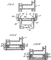
- the limb 3 has upstanding projections 8 and 9 formed intergrally therewith, these projections having pawls 14 and 15 formed thereon as is best shown in Figure 4.
- the projections 8 and 9 are connected at either end to the limb 3 of the device and thus form springs.
- Each limb of the device has a hinged pair 10 and 11 of secondary locking wedges hinged to the outer surface of each limb.
- the hinged locking wedges 10 are hinged at points 20 and 21 to the limb 3.
- the hinged unit 10 comprises secondary locking wedges 12 and 13 which are generally of triangular shape.
- the window frame 1 has grooves 18 and 19 formed in the underneath thereof, these grooves being adapted to receive not only the primary locking clips 8 and 9, but also the secondary locking wedges 12 and 13.
- the primary locking wedges 8 and 9 are pushed into the grooves 18 and 19 formed in the window frame unit 1.
- the primary clips 8 and 9 are pushed into position in the grooves merely by applying a reasonable amount of finger pressure.
- the primary locking clips 8 and 9 in position in grooves 18 and 19 can best be seen in Figure 6.
- the hinged unit 10 is then pivoted about hinges 20 and 21 so that the secondary locking wedges 12 and 13 pass through the elongate slots 16 and 17, respectively, adjacent the primary locking clips 8 and 9 and are then pushed into the grooves 18 and 19 to lock the primary locking clips 18 and 19 in position.
- the grooves 18 and 19 as shown in the drawings are undercut and thus the pawls 14 and 15 formed on the primary locking clips 8 and 9 are pushed into the grooves, thus helping to lock them into position.
- the reverse procedure can be adapted in order to remove the corner protetion unit 2 from the window frame 1.
- each limb 3 and 4 On its outer face, each limb 3 and 4 has two transversely extending projections 22 which are longitudinally spaced from each other. Each projection 22 is rounded in cross-section. These projections, together with the walls 6 and 7, provide support for the device when it is stored upon the ground. Furthermore, the rounded projections 22 assist in enabling a protected window frame to be slid along the ground surface quite smoothly. Construction of the device is such that the corner protection unit is locked in position, so that if the free end of one limb 3 or 4 were to catch on something, the device would not readily peel off from the window frame.
- the corner protection device has been described with reference to a frame with undercut grooves 18 and 19, the device in the present invention is adaptable for use with grooves which are not undercut. In these circumstances, a friction fit is achieved which locks the clips into position on the window frame. In this variation, the pawls 14 and 15 which located the undercut grooves are removed and the wedging action between the primary and secondary locking members is relied upon to achieve the necessary locking action by interference fit.
Landscapes
- Engineering & Computer Science (AREA)
- Mechanical Engineering (AREA)
- Securing Of Glass Panes Or The Like (AREA)
- Clamps And Clips (AREA)
Applications Claiming Priority (2)
| Application Number | Priority Date | Filing Date | Title |
|---|---|---|---|
| GB9211224 | 1992-05-27 | ||
| GB929211224A GB9211224D0 (en) | 1992-05-27 | 1992-05-27 | A corner protection device |
Publications (3)
| Publication Number | Publication Date |
|---|---|
| EP0573181A2 true EP0573181A2 (de) | 1993-12-08 |
| EP0573181A3 EP0573181A3 (de) | 1994-12-28 |
| EP0573181B1 EP0573181B1 (de) | 1996-12-04 |
Family
ID=10716096
Family Applications (1)
| Application Number | Title | Priority Date | Filing Date |
|---|---|---|---|
| EP93303926A Expired - Lifetime EP0573181B1 (de) | 1992-05-27 | 1993-05-20 | Eckenschutzeinrichtung |
Country Status (3)
| Country | Link |
|---|---|
| EP (1) | EP0573181B1 (de) |
| DE (1) | DE69306311D1 (de) |
| GB (1) | GB9211224D0 (de) |
Cited By (5)
| Publication number | Priority date | Publication date | Assignee | Title |
|---|---|---|---|---|
| US5848865A (en) * | 1997-09-08 | 1998-12-15 | Ireco, Inc. | Lading tie-down strap protector |
| WO2001053166A1 (en) * | 2000-01-24 | 2001-07-26 | Forrest Smith | Unitary product cushioning structure |
| KR102306529B1 (ko) * | 2020-03-26 | 2021-09-30 | 주식회사 샤바스 | 코너 모서리 보호구 |
| CN114803137A (zh) * | 2022-04-14 | 2022-07-29 | 江苏吉祥瑞合幕墙科技有限公司 | 一种铝单板生产用边角保护装置及保护方法 |
| GB2617860A (en) * | 2022-04-22 | 2023-10-25 | Truframe Ltd | A corner protector |
Families Citing this family (1)
| Publication number | Priority date | Publication date | Assignee | Title |
|---|---|---|---|---|
| CN102152892B (zh) * | 2011-05-25 | 2012-07-04 | 长春阔尔科技股份有限公司 | 窗扇固定垫块 |
Family Cites Families (2)
| Publication number | Priority date | Publication date | Assignee | Title |
|---|---|---|---|---|
| DE2426723C3 (de) * | 1974-06-01 | 1978-04-20 | Hans-Werner 4830 Guetersloh Duepree | Mit Folienscharnier klappbar ausgebildeter Eckverbinder für brettförmige Bauteile |
| GB2221942B (en) * | 1988-08-18 | 1992-07-01 | Glazpart Ltd | A window-unit corner protection device |
-
1992
- 1992-05-27 GB GB929211224A patent/GB9211224D0/en active Pending
-
1993
- 1993-05-20 EP EP93303926A patent/EP0573181B1/de not_active Expired - Lifetime
- 1993-05-20 DE DE69306311T patent/DE69306311D1/de not_active Expired - Lifetime
Cited By (8)
| Publication number | Priority date | Publication date | Assignee | Title |
|---|---|---|---|---|
| US5848865A (en) * | 1997-09-08 | 1998-12-15 | Ireco, Inc. | Lading tie-down strap protector |
| WO2001053166A1 (en) * | 2000-01-24 | 2001-07-26 | Forrest Smith | Unitary product cushioning structure |
| US6520337B2 (en) | 2000-01-24 | 2003-02-18 | Forrest Smith | Unitary product cushioning structure |
| KR102306529B1 (ko) * | 2020-03-26 | 2021-09-30 | 주식회사 샤바스 | 코너 모서리 보호구 |
| CN114803137A (zh) * | 2022-04-14 | 2022-07-29 | 江苏吉祥瑞合幕墙科技有限公司 | 一种铝单板生产用边角保护装置及保护方法 |
| CN114803137B (zh) * | 2022-04-14 | 2023-12-19 | 江苏吉祥瑞合幕墙科技有限公司 | 一种铝单板生产用边角保护装置及保护方法 |
| GB2617860A (en) * | 2022-04-22 | 2023-10-25 | Truframe Ltd | A corner protector |
| GB2617860B (en) * | 2022-04-22 | 2025-04-16 | Truframe Ltd | A corner protector |
Also Published As
| Publication number | Publication date |
|---|---|
| EP0573181A3 (de) | 1994-12-28 |
| DE69306311D1 (de) | 1997-01-16 |
| GB9211224D0 (en) | 1992-07-08 |
| EP0573181B1 (de) | 1996-12-04 |
Similar Documents
| Publication | Publication Date | Title |
|---|---|---|
| US11731824B2 (en) | Package comprising means for retaining an object | |
| CA2019189C (en) | Resealable enclosure | |
| US3446345A (en) | Sash protectors | |
| CN107148301B (zh) | 运输容器和插入件 | |
| US5090568A (en) | Glass slide mailer | |
| EP0573181B1 (de) | Eckenschutzeinrichtung | |
| HUP9902865A2 (hu) | Zárható doboz és dobozpalást | |
| US4774779A (en) | Holder for a stack of pictures | |
| US4167230A (en) | Disposable receiver | |
| WO2005021403A1 (en) | Sheet packaging apparatus | |
| GB2079726A (en) | Self-locking tape cassette box | |
| US4587730A (en) | Sleeve for disposable safety razor | |
| US20070126248A1 (en) | Door propping method and device | |
| US4761935A (en) | Device for retaining carton flaps in closed or open position | |
| GB2236048A (en) | Foldable valance | |
| AU662799B2 (en) | Clamp for paper sheets | |
| GB2221942A (en) | A window-unit corner protection device | |
| WO1997005354A1 (en) | Theftproof container | |
| US5460268A (en) | Band apparatus for reel assembly | |
| CN222592030U (zh) | 产品包装盒 | |
| FI100788B (fi) | Tarranauha ja turvapussi | |
| JP3080144U (ja) | 通い箱の折畳み構造 | |
| WO1996012654A1 (en) | Tamper-proof cargo seal | |
| EP0810605A2 (de) | Behälter für Plattenkassette | |
| RU193815U1 (ru) | Односторонняя клейкая лента для упаковки пачек стекла |
Legal Events
| Date | Code | Title | Description |
|---|---|---|---|
| PUAI | Public reference made under article 153(3) epc to a published international application that has entered the european phase |
Free format text: ORIGINAL CODE: 0009012 |
|
| AK | Designated contracting states |
Kind code of ref document: A2 Designated state(s): DE FR GB |
|
| PUAL | Search report despatched |
Free format text: ORIGINAL CODE: 0009013 |
|
| AK | Designated contracting states |
Kind code of ref document: A3 Designated state(s): DE FR GB |
|
| 17P | Request for examination filed |
Effective date: 19950627 |
|
| GRAG | Despatch of communication of intention to grant |
Free format text: ORIGINAL CODE: EPIDOS AGRA |
|
| GRAH | Despatch of communication of intention to grant a patent |
Free format text: ORIGINAL CODE: EPIDOS IGRA |
|
| 17Q | First examination report despatched |
Effective date: 19960502 |
|
| GRAH | Despatch of communication of intention to grant a patent |
Free format text: ORIGINAL CODE: EPIDOS IGRA |
|
| GRAA | (expected) grant |
Free format text: ORIGINAL CODE: 0009210 |
|
| AK | Designated contracting states |
Kind code of ref document: B1 Designated state(s): DE FR GB |
|
| PG25 | Lapsed in a contracting state [announced via postgrant information from national office to epo] |
Ref country code: FR Effective date: 19961204 |
|
| RIN1 | Information on inventor provided before grant (corrected) |
Inventor name: RHODES, DAVID Inventor name: HOWE, NICHOLAS JOHN |
|
| REF | Corresponds to: |
Ref document number: 69306311 Country of ref document: DE Date of ref document: 19970116 |
|
| PG25 | Lapsed in a contracting state [announced via postgrant information from national office to epo] |
Ref country code: DE Effective date: 19970305 |
|
| EN | Fr: translation not filed | ||
| PLBE | No opposition filed within time limit |
Free format text: ORIGINAL CODE: 0009261 |
|
| STAA | Information on the status of an ep patent application or granted ep patent |
Free format text: STATUS: NO OPPOSITION FILED WITHIN TIME LIMIT |
|
| 26N | No opposition filed | ||
| REG | Reference to a national code |
Ref country code: GB Ref legal event code: IF02 |
|
| PGFP | Annual fee paid to national office [announced via postgrant information from national office to epo] |
Ref country code: GB Payment date: 20100525 Year of fee payment: 18 |
|
| GBPC | Gb: european patent ceased through non-payment of renewal fee |
Effective date: 20110520 |
|
| PG25 | Lapsed in a contracting state [announced via postgrant information from national office to epo] |
Ref country code: GB Free format text: LAPSE BECAUSE OF NON-PAYMENT OF DUE FEES Effective date: 20110520 |