EP0573222A1 - Heizgeräte - Google Patents
Heizgeräte Download PDFInfo
- Publication number
- EP0573222A1 EP0573222A1 EP93304162A EP93304162A EP0573222A1 EP 0573222 A1 EP0573222 A1 EP 0573222A1 EP 93304162 A EP93304162 A EP 93304162A EP 93304162 A EP93304162 A EP 93304162A EP 0573222 A1 EP0573222 A1 EP 0573222A1
- Authority
- EP
- European Patent Office
- Prior art keywords
- gas
- pilot
- burner
- main
- gas valve
- Prior art date
- Legal status (The legal status is an assumption and is not a legal conclusion. Google has not performed a legal analysis and makes no representation as to the accuracy of the status listed.)
- Withdrawn
Links
Images
Classifications
-
- F—MECHANICAL ENGINEERING; LIGHTING; HEATING; WEAPONS; BLASTING
- F23—COMBUSTION APPARATUS; COMBUSTION PROCESSES
- F23N—REGULATING OR CONTROLLING COMBUSTION
- F23N5/00—Systems for controlling combustion
- F23N5/02—Systems for controlling combustion using devices responsive to thermal changes or to thermal expansion of a medium
- F23N5/022—Systems for controlling combustion using devices responsive to thermal changes or to thermal expansion of a medium using electronic means
-
- F—MECHANICAL ENGINEERING; LIGHTING; HEATING; WEAPONS; BLASTING
- F23—COMBUSTION APPARATUS; COMBUSTION PROCESSES
- F23N—REGULATING OR CONTROLLING COMBUSTION
- F23N5/00—Systems for controlling combustion
- F23N5/20—Systems for controlling combustion with a time program acting through electrical means, e.g. using time-delay relays
- F23N5/203—Systems for controlling combustion with a time program acting through electrical means, e.g. using time-delay relays using electronic means
-
- F—MECHANICAL ENGINEERING; LIGHTING; HEATING; WEAPONS; BLASTING
- F23—COMBUSTION APPARATUS; COMBUSTION PROCESSES
- F23N—REGULATING OR CONTROLLING COMBUSTION
- F23N2227/00—Ignition or checking
- F23N2227/22—Pilot burners
-
- F—MECHANICAL ENGINEERING; LIGHTING; HEATING; WEAPONS; BLASTING
- F23—COMBUSTION APPARATUS; COMBUSTION PROCESSES
- F23N—REGULATING OR CONTROLLING COMBUSTION
- F23N2227/00—Ignition or checking
- F23N2227/22—Pilot burners
- F23N2227/24—Pilot burners the pilot burner not burning continuously
-
- F—MECHANICAL ENGINEERING; LIGHTING; HEATING; WEAPONS; BLASTING
- F23—COMBUSTION APPARATUS; COMBUSTION PROCESSES
- F23N—REGULATING OR CONTROLLING COMBUSTION
- F23N2227/00—Ignition or checking
- F23N2227/28—Ignition circuits
- F23N2227/30—Ignition circuits for pilot burners
-
- F—MECHANICAL ENGINEERING; LIGHTING; HEATING; WEAPONS; BLASTING
- F23—COMBUSTION APPARATUS; COMBUSTION PROCESSES
- F23N—REGULATING OR CONTROLLING COMBUSTION
- F23N2227/00—Ignition or checking
- F23N2227/36—Spark ignition, e.g. by means of a high voltage
-
- F—MECHANICAL ENGINEERING; LIGHTING; HEATING; WEAPONS; BLASTING
- F23—COMBUSTION APPARATUS; COMBUSTION PROCESSES
- F23N—REGULATING OR CONTROLLING COMBUSTION
- F23N2229/00—Flame sensors
-
- F—MECHANICAL ENGINEERING; LIGHTING; HEATING; WEAPONS; BLASTING
- F23—COMBUSTION APPARATUS; COMBUSTION PROCESSES
- F23N—REGULATING OR CONTROLLING COMBUSTION
- F23N2233/00—Ventilators
- F23N2233/06—Ventilators at the air intake
-
- F—MECHANICAL ENGINEERING; LIGHTING; HEATING; WEAPONS; BLASTING
- F23—COMBUSTION APPARATUS; COMBUSTION PROCESSES
- F23N—REGULATING OR CONTROLLING COMBUSTION
- F23N2235/00—Valves, nozzles or pumps
- F23N2235/12—Fuel valves
- F23N2235/14—Fuel valves electromagnetically operated
-
- F—MECHANICAL ENGINEERING; LIGHTING; HEATING; WEAPONS; BLASTING
- F23—COMBUSTION APPARATUS; COMBUSTION PROCESSES
- F23N—REGULATING OR CONTROLLING COMBUSTION
- F23N2235/00—Valves, nozzles or pumps
- F23N2235/12—Fuel valves
- F23N2235/18—Groups of two or more valves
-
- F—MECHANICAL ENGINEERING; LIGHTING; HEATING; WEAPONS; BLASTING
- F23—COMBUSTION APPARATUS; COMBUSTION PROCESSES
- F23N—REGULATING OR CONTROLLING COMBUSTION
- F23N5/00—Systems for controlling combustion
- F23N5/18—Systems for controlling combustion using detectors sensitive to rate of flow of air or fuel
Definitions
- This invention relates to heating appliances, and more especially to gas fired heating appliances such as hot water boilers for gas central heating systems. It is especially concerned with control systems for use in such heating appliances.
- the Permanent Pilot system already widely used on gas boilers has the advantage of being cost effective and rapid in its response to a demand for heat. Unfortunately, the system possesses a significant disadvantage in that the pilot consumes costly gas continuously.
- the Full Sequence Control system does not waste pilot gas when there is no heat demand, but invariably takes longer to initiate a light up when a call is made. Also the system is much more complicated and costly to produce.
- a gas fired heating appliance comprising a main burner and a pilot burner, a main gas valve for controlling the supply of gas to said main gas burner, a pilot gas valve for controlling the supply of gas to said pilot gas burner, and a control system operable in response to an external signal for causing said pilot gas burner to be lit, and when lit for causing an output signal to be generated for application to said main gas valve, said appliance including an internal thermostat for connecting said output signal to said main gas valve whereby said pilot gas valve operates to supply gas to said pilot gas burner only in response to said external signal, and said main gas valve operates to supply gas to said main burner only in response to said external signal and the operation of said internal thermostat.
- said control system incorporates a full sequence control.
- said main gas valve is supplied with gas from said pilot gas valve.
- a heating appliance in accordance with the preferred form of the invention offers all of the advantages of a full sequence control system AND a reduction in full sequence ignition attempts which cuts down noise, system wear, and electrical interference generation by, for example, the ignition spark generator.
- a control system may be described by the general term "Semi-Permanent Pilot".
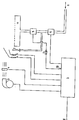
- FIG. 1 is a block schematic diagram of a control system for use in a heating appliance in accordance with the present invention.
- the control system shown in the drawing employs a full sequence control 2 which supervises the safe light-up of a pilot burner 7 and subsequently a main burner 10.
- the full sequence control is operated in conjunction with the components shown, such as a fan 3 to provide the air supply for combustion, an air pressure switch 4 to signal to the control 2 that the fan 3 is operating adequately, and an igniting electrode or filament 5 for the lighting the pilot burner 7 and which may or may not be combined in function with a flame sensor 6 for sensing the presence of a flame on the pilot burner 7.
- the output at point 13 would normally be applied directly to the main gas valve 8 which feeds gas to the main gas burner 10, which is subsequently caused to be lit by the pilot burner 7.
- the main burner 10 remains lit until the call for heat 1 is removed.
- the call for heat 1 applied to the full sequence control 2 may typically be derived from a time switch, an external e.g. room thermostat, or an internal appliance thermostat. In this way, whenever there is a call for heat 1 applied to the full sequence control 2, whether this be derived externally or internally, a full light-up routine is used to light the main burner 10.
- the pilot burner 7 is caused to be lit, and when the flame thereof has been sensed by the flame sensor 6, an output is afforded at point 13 of the control 2.
- the appliance thermostat 12 is closed, i.e. calling for heat after this point, the signal from point 13 will be applied to the main gas valve 8 to feed gas to the main burner 10 to enable full operation of the appliance.
- the appliance thermostat 12 is open at this point, i.e. the appliance temperature is above its minimum limit, no signal will be applied to the main gas valve 8, and the light-up routine which would normally have been expected is obviated.
- the semi-permanent pilot system here described produces less electrical and audible noise, is faster in response to internal thermostat heat demands and produces less wear on the controls than a conventional full sequence system where each internal demand instigates a full light-up routine. Also, the use of fuel gas is reduced from that consumed by the permanent pilot system.
- heating appliance control system which has been described is particularly applicable to heating appliances incorporating full system control, it should be appreciated that all aspects of a conventional full sequence control are not essential for implementing the invention.
- the fan 3 and air pressure switch 4 may be dispensed with.
Landscapes
- Engineering & Computer Science (AREA)
- Chemical & Material Sciences (AREA)
- Combustion & Propulsion (AREA)
- Mechanical Engineering (AREA)
- General Engineering & Computer Science (AREA)
- Control Of Combustion (AREA)
- Regulation And Control Of Combustion (AREA)
Applications Claiming Priority (2)
| Application Number | Priority Date | Filing Date | Title |
|---|---|---|---|
| GB929211825A GB9211825D0 (en) | 1992-05-30 | 1992-05-30 | Heating appliances |
| GB9211825 | 1992-05-30 |
Publications (1)
| Publication Number | Publication Date |
|---|---|
| EP0573222A1 true EP0573222A1 (de) | 1993-12-08 |
Family
ID=10716525
Family Applications (1)
| Application Number | Title | Priority Date | Filing Date |
|---|---|---|---|
| EP93304162A Withdrawn EP0573222A1 (de) | 1992-05-30 | 1993-05-28 | Heizgeräte |
Country Status (2)
| Country | Link |
|---|---|
| EP (1) | EP0573222A1 (de) |
| GB (2) | GB9211825D0 (de) |
Cited By (3)
| Publication number | Priority date | Publication date | Assignee | Title |
|---|---|---|---|---|
| EP0727613A1 (de) * | 1995-02-20 | 1996-08-21 | John Stuart Fleming | Verfahren und Vorrichtung zur Regelung eines Heizgerätes für entflammbares Fluidum |
| EP0837283A1 (de) * | 1996-10-16 | 1998-04-22 | SIT LA PRECISA S.r.l. | Selbsttätiges Regelsystem mit doppeltem Sicherheitsschutz für einen intermittierend funktionierenden Gasbrenner |
| CN106196163A (zh) * | 2016-08-02 | 2016-12-07 | 贵州钢绳股份有限公司 | 用于酸洗槽浸槽加热的燃烧器电气控制系统 |
Families Citing this family (1)
| Publication number | Priority date | Publication date | Assignee | Title |
|---|---|---|---|---|
| GB2283565B (en) * | 1993-11-04 | 1997-10-15 | Blue Circle Heating Ltd | Fuel burning appliances |
Citations (3)
| Publication number | Priority date | Publication date | Assignee | Title |
|---|---|---|---|---|
| JPS5849827A (ja) * | 1981-09-19 | 1983-03-24 | Rinnai Corp | 燃焼制御装置 |
| JPS5875620A (ja) * | 1981-10-29 | 1983-05-07 | Matsushita Electric Ind Co Ltd | 燃焼制御回路 |
| JPH01318809A (ja) * | 1988-06-17 | 1989-12-25 | Matsushita Electric Ind Co Ltd | 火力切換装置 |
Family Cites Families (2)
| Publication number | Priority date | Publication date | Assignee | Title |
|---|---|---|---|---|
| GB589963A (en) * | 1944-07-05 | 1947-07-04 | Robertshaw Thermostat Co | Improvements in or relating to safety control systems for heating apparatus |
| CA1051768A (en) * | 1974-10-07 | 1979-04-03 | Elmer A. Carlson | Spark ignited recycling ignition system with interlocking gas valve control |
-
1992
- 1992-05-30 GB GB929211825A patent/GB9211825D0/en active Pending
-
1993
- 1993-05-28 EP EP93304162A patent/EP0573222A1/de not_active Withdrawn
- 1993-05-28 GB GB9311019A patent/GB2267336B/en not_active Expired - Fee Related
Patent Citations (3)
| Publication number | Priority date | Publication date | Assignee | Title |
|---|---|---|---|---|
| JPS5849827A (ja) * | 1981-09-19 | 1983-03-24 | Rinnai Corp | 燃焼制御装置 |
| JPS5875620A (ja) * | 1981-10-29 | 1983-05-07 | Matsushita Electric Ind Co Ltd | 燃焼制御回路 |
| JPH01318809A (ja) * | 1988-06-17 | 1989-12-25 | Matsushita Electric Ind Co Ltd | 火力切換装置 |
Non-Patent Citations (3)
| Title |
|---|
| PATENT ABSTRACTS OF JAPAN vol. 007, no. 133 (M - 221) 10 June 1983 (1983-06-10) * |
| PATENT ABSTRACTS OF JAPAN vol. 007, no. 169 (M - 231) 26 July 1983 (1983-07-26) * |
| PATENT ABSTRACTS OF JAPAN vol. 014, no. 121 (M - 946) 7 March 1990 (1990-03-07) * |
Cited By (4)
| Publication number | Priority date | Publication date | Assignee | Title |
|---|---|---|---|---|
| EP0727613A1 (de) * | 1995-02-20 | 1996-08-21 | John Stuart Fleming | Verfahren und Vorrichtung zur Regelung eines Heizgerätes für entflammbares Fluidum |
| EP0837283A1 (de) * | 1996-10-16 | 1998-04-22 | SIT LA PRECISA S.r.l. | Selbsttätiges Regelsystem mit doppeltem Sicherheitsschutz für einen intermittierend funktionierenden Gasbrenner |
| CN106196163A (zh) * | 2016-08-02 | 2016-12-07 | 贵州钢绳股份有限公司 | 用于酸洗槽浸槽加热的燃烧器电气控制系统 |
| CN106196163B (zh) * | 2016-08-02 | 2018-06-12 | 贵州钢绳股份有限公司 | 用于酸洗槽浸槽加热的燃烧器电气控制系统 |
Also Published As
| Publication number | Publication date |
|---|---|
| GB9311019D0 (en) | 1993-07-14 |
| GB2267336A (en) | 1993-12-01 |
| GB2267336B (en) | 1994-05-18 |
| GB9211825D0 (en) | 1992-07-15 |
Similar Documents
| Publication | Publication Date | Title |
|---|---|---|
| US5787874A (en) | Gas-fired ceramic-cooktop burner | |
| US4457692A (en) | Dual firing rate flame sensing system | |
| US3887325A (en) | Control method and apparatus for burners | |
| US4086048A (en) | Spark ignited recycling ignition system with interlocking gas valve control | |
| US4190414A (en) | Fail-safe gas feed and ignition sequence control apparatus and method for a gas-fired appliance | |
| GB2240841A (en) | Igniting a vitreous ceramic hotplate of a cooking appliance | |
| ES465727A1 (es) | Perfeccionamientos en sistemas de gobierno para quemadores oradiadores electricos. | |
| US4581697A (en) | Controller for combustible fuel burner | |
| CA1238392A (en) | Adaptive low fire hold control system | |
| GB2267336A (en) | Control of heating appliance | |
| GB2249382A (en) | Flame responsive gas burner ignition | |
| US4168949A (en) | Flame signal stabilization circuit | |
| US5453002A (en) | Fuel saving pilot control valve | |
| KR0157231B1 (ko) | 소음감소를 위한 보일러 제어방법 | |
| JP2933876B2 (ja) | 多缶設置ボイラの運転制御方法 | |
| GB2401930A (en) | A method and device for igniting an oil burner | |
| US4102630A (en) | Burner control system | |
| IES960473A2 (en) | A control system for gas cooker | |
| EP0340032A3 (de) | Gaskocher | |
| KR920005387Y1 (ko) | 가스 연소기 | |
| JPH0252920A (ja) | 給湯器の排気ファン回転速度制御装置 | |
| US4451227A (en) | Flame safeguard sequencer having switch test functions | |
| GB2283565A (en) | Fuel burning appliance | |
| EP1130320A1 (de) | Regelanlage für Kessel | |
| JPS636609Y2 (de) |
Legal Events
| Date | Code | Title | Description |
|---|---|---|---|
| PUAI | Public reference made under article 153(3) epc to a published international application that has entered the european phase |
Free format text: ORIGINAL CODE: 0009012 |
|
| AK | Designated contracting states |
Kind code of ref document: A1 Designated state(s): DE FR GB IT NL |
|
| 17P | Request for examination filed |
Effective date: 19940513 |
|
| STAA | Information on the status of an ep patent application or granted ep patent |
Free format text: STATUS: THE APPLICATION IS DEEMED TO BE WITHDRAWN |
|
| 18D | Application deemed to be withdrawn |
Effective date: 19951201 |