EP0573300A2 - Verbrennungsverfahren mit niedrigem NOx-Gehalt und Brennervorrichtung zur Durchführung des Verfahrens - Google Patents
Verbrennungsverfahren mit niedrigem NOx-Gehalt und Brennervorrichtung zur Durchführung des Verfahrens Download PDFInfo
- Publication number
- EP0573300A2 EP0573300A2 EP93304333A EP93304333A EP0573300A2 EP 0573300 A2 EP0573300 A2 EP 0573300A2 EP 93304333 A EP93304333 A EP 93304333A EP 93304333 A EP93304333 A EP 93304333A EP 0573300 A2 EP0573300 A2 EP 0573300A2
- Authority
- EP
- European Patent Office
- Prior art keywords
- burner
- combustion air
- fuel
- throat
- primary
- Prior art date
- Legal status (The legal status is an assumption and is not a legal conclusion. Google has not performed a legal analysis and makes no representation as to the accuracy of the status listed.)
- Granted
Links
Images


Classifications
-
- F—MECHANICAL ENGINEERING; LIGHTING; HEATING; WEAPONS; BLASTING
- F23—COMBUSTION APPARATUS; COMBUSTION PROCESSES
- F23C—METHODS OR APPARATUS FOR COMBUSTION USING FLUID FUEL OR SOLID FUEL SUSPENDED IN A CARRIER GAS OR AIR
- F23C6/00—Combustion apparatus characterised by the combination of two or more combustion chambers or combustion zones, e.g. for staged combustion
- F23C6/04—Combustion apparatus characterised by the combination of two or more combustion chambers or combustion zones, e.g. for staged combustion in series connection
- F23C6/045—Combustion apparatus characterised by the combination of two or more combustion chambers or combustion zones, e.g. for staged combustion in series connection with staged combustion in a single enclosure
- F23C6/047—Combustion apparatus characterised by the combination of two or more combustion chambers or combustion zones, e.g. for staged combustion in series connection with staged combustion in a single enclosure with fuel supply in stages
-
- F—MECHANICAL ENGINEERING; LIGHTING; HEATING; WEAPONS; BLASTING
- F23—COMBUSTION APPARATUS; COMBUSTION PROCESSES
- F23D—BURNERS
- F23D14/00—Burners for combustion of a gas, e.g. of a gas stored under pressure as a liquid
- F23D14/20—Non-premix gas burners, i.e. in which gaseous fuel is mixed with combustion air on arrival at the combustion zone
- F23D14/22—Non-premix gas burners, i.e. in which gaseous fuel is mixed with combustion air on arrival at the combustion zone with separate air and gas feed ducts, e.g. with ducts running parallel or crossing each other
-
- F—MECHANICAL ENGINEERING; LIGHTING; HEATING; WEAPONS; BLASTING
- F23—COMBUSTION APPARATUS; COMBUSTION PROCESSES
- F23D—BURNERS
- F23D14/00—Burners for combustion of a gas, e.g. of a gas stored under pressure as a liquid
- F23D14/46—Details
- F23D14/72—Safety devices, e.g. operative in case of failure of gas supply
- F23D14/74—Preventing flame lift-off
-
- F—MECHANICAL ENGINEERING; LIGHTING; HEATING; WEAPONS; BLASTING
- F23—COMBUSTION APPARATUS; COMBUSTION PROCESSES
- F23C—METHODS OR APPARATUS FOR COMBUSTION USING FLUID FUEL OR SOLID FUEL SUSPENDED IN A CARRIER GAS OR AIR
- F23C2201/00—Staged combustion
- F23C2201/20—Burner staging
-
- F—MECHANICAL ENGINEERING; LIGHTING; HEATING; WEAPONS; BLASTING
- F23—COMBUSTION APPARATUS; COMBUSTION PROCESSES
- F23C—METHODS OR APPARATUS FOR COMBUSTION USING FLUID FUEL OR SOLID FUEL SUSPENDED IN A CARRIER GAS OR AIR
- F23C2201/00—Staged combustion
- F23C2201/30—Staged fuel supply
Definitions
- the present invention relates to a method of low-NOx combustion and a burner device for effecting the same. More particularly, the invention is directed to an improvement of a two-stage low-NOx combustion method and a two stage firing burner device for carrying out the method.
- a two-stage method comprising two fuel supply stages for doing the combustion at two stages, as disclosed, for instance, from the Japanese Patent No. 1104160.
- this method will be referred to as "two-stage fuel combustion method”.
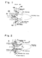
- Such two-stage fuel combustion method is normally executed by a burner device as shown in Fig. 1.
- a burner device BD' which has a burner throat 103 formed therein and one piece of primary fuel nozzle 101 disposed within the burner throat 103. Further, a plurality of secondary fuel nozzles 102 are provided around the outside opening of the burner throat 103.
- Each of those secondary fuel nozzles 102 is oriented toward a primary flame which is to be flowed out from the burner throat 103.
- a whole amount of combustion air (as designated by "Air” in Fig. 1) is supplied in the throat 103, and a primary fuel is injected from the primary fuel nozzle 101 toward the combustion air, such that the primary fuel is embraced or circumscribed by the air, to thereby effect a combustion and create the primary flame.
- a secondary fuel is injected from the secondary fuel nozzles 102 toward the thus-created primary flame, creating thus a secondary flame.
- the first combustion stage uses the whole amount of combustion air to burn the primary fuel under a proper excess air condition set by an suitable excess air ratio (i.e. the so-called "air rich” condition), and then, the secondary fuel is injected to such first combustion, reducing a part of NOx existing in the primary flame and thereafter bringing the primary fuel in contact with the downstream portion of combustion air which remains not burned through the primary flame, so as to effect a second combustion, creating a secondary flame.
- a proper excess air condition set by an suitable excess air ratio
- the above-described conventional method and burner device inject out the combustion air from the burner throat 103, in such a way that the primary flame is surrounded by the air, which has been found defective in that the combustion air, which flows in the thin-arrow direction in Fig. 1, results in expanding its stream at the exit of burner throat 103 as indicated by the arrow A2, and the expanded portion of air directly contacts the secondary fuel injected from the secondary fuel nozzles 102, causing a combustion in this particular area.
- a part of the secondary fuel is directly contacted with such leaked air (A2) before contact with the primary flame, starting thus a secondary combustion in advance. Consequently, the combustion air is not fully used to reduce the NOx in the primary flame and there is a problem of insufficient NOx reduction.
- this prior-art technique serves the low NOx purpose based on the thick and thin fuel combustion principle, more effectively than most of ordinary combustion techniques, yet there is a room of improvement for the reason above.
- a burner device for the low-NOx combustion which comprises: a burner throat means through which a substantially whole amount of combustion air is injected; a first injection means for injecting a primary fuel towards said combustion air, which first injection means is provided in the burner throat means and having an injection axis oriented towards a central axis of the burner throat; a secondary injection means for injecting a secondary fuel in a direction towards the primary fuel from outside thereof.
- the injection axis of the first injection means is oriented at an angle in a direction towards a downstream with respect to the combustion air in order to inject the primary fuel to the combustion air in such direction.
- the injection axis of the first injection means may be oriented in a direction tangential to the inner surface of the burner throat means, to thereby inject the primary fuel to the combustion air it that tangential direction so as to create a generally cylindrical primary flame in a vortex manner.
- the burner throat manes may be of a generally cylindrical shape and the first injection means may comprise a plurality of nozzles disposed along such cylindrical shape of burner throat means, so that the primary fuel is injected in a direction from the circumference of circle towards the combustion air, thereby creating a generally circular cylindrical shape of primary flame.
- the burner throat means may be of a rectangular cylindrical shape and the first injection means may comprise a plurality of nozzles along such rectangular cylindrical shape of burner throat means, so that the primary fuel is injected in a direction from the rectangular line towards the combustion air, thereby creating a flat configuration of primary flame having a generally rectangular cross-section.
- two or more first injection means may be provided equidistantly in the inner surface of the burner throat means, and also two or more second injection means be provided adjacent to the exit of the burner throat means.
- the burner throat means may a burner tile throat disposed at at downstream side with respect to the combustion air, and inner throat member disposed at an upstream side with respect to the same air, the inner throat member extending towards the inside of burner tile throat in registry with an inner surface of the same burner tile throat, and further the first injection means may be provided between those burner tile throat and inner throat member.
- the second injection means may be provided adjacent the exit of burner tile throat such as to be oriented towards the central axis of those burner throat elements.
- a baffle plate may preferably be provide adjacent to the injection holes of the first injection means and further disposed at an upstream side relative to the combustion air.
- an air velocity adjustment means be provided within the burner throat means such as to be disposed coaxially relative to the central axis of burner throat means, whereby a velocity distribution of the combustion air injected through the burner throat means may be adjusted properly in order to insure a better formation of the cylindrical primary flame.
- the formation of generally cylindrical primary flame serves to cover or encircle the combustion air, earlier than the injection of the secondary fuel to the air, to thereby shield the air form the secondary fuel while at the same time, the NOx in the primary flame is reduced by the secondary fuel. Thereafter, a second combustion is effected by bringing the secondary fuel to contact with the portion of combustion air at the downstream side.
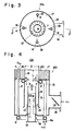
- Fig. 2 schematically shows a principle of low-NOx combustion in the present invention. Basically, this is similar to the previously described prior-art two-stage fuel combustion method in terms of the first and second fuel supply stages involving injection of primary fuel to the combustion air and subsequent injection of secondary fuel to the downstream portion of the air.
- a substantially whole amount of combustion air A is supplied and subject to a first combustion by a primary fuel F1 being injected thereto, and then, the downstream portion of the same air A (adjacent to the inside of combustion chamber CH) is subject to a second combustion by injection of a secondary fuel F2 thereto.
- a substantially whole amount of combustion air A is intended to entail the case where a part of the air A may be utilized as a cooling air for cooling the secondary nozzles 4. But, in the actual combustion process, it can be regarded as a whole amount of combustion air A to which the primary fuel F1 is injected.
- the ratio of distribution between the primary and secondary fuels F1, F2 with respect to the combustion air A may be set at any proper degree, which is not limitative, but for example, may be set by a proper ratio out of 90 - 30% by volume of secondary fuel F2 against 10 - 70% by volume of primary fuel F1.
- Designations 1, 4 and 19 denote a primary fuel nozzle for injecting the primary fuel F1, a secondary fuel nozzle or injecting the secondary fuel F2 and a burner throat, respectively.
- the low-NOx combustion method in the present invention essentially includes a first stage where the primary fuel F1 is injected in a direction from the periphery of stream of the combustion air A flowing in the burner throat 19, towards the air A per se, and ignited by a pilot burner (not shown) or the like to start a combustion and create a generally cylindrical shape of primary flame B1 confirming generally to the inner surfaces of burner throat 19, so that the primary flame B1 surrounds or circumscribes the combustion air A.
- a pilot burner not shown
- at least two or more primary fuel nozzles 1 should be provided in order to produce such cylindrical primary flame B1 and preferably those plural nozzles 1 be disposed equidistantly along the inner surfaces of or circumferentially of the burner throat 19.
- the secondary fuel F2 is contacted with the remaining combustion air A' penetrating through that primary flame B1, to thereby perform a second combustion.
- a secondary flame as designated by B2 is created at the side of combustion chamber CH.
- combustion air A injection from the burner throat 19 is shielded on the peripheral region by the primary flame B1 from the secondary so as to insure that the NOx in the primary flame B1 is reduced by the secondary fuel F2, and thereafter the air is fully burned by the same secondary fuel F2.
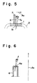
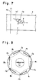
- FIGs. 3 through 6 there is illustrated a first embodiment of burner device for effecting the above-described low-NOx combustion method.
- a cylindrical burner device BD1 having a cylindrical burner casing 15.
- Both burner tile throat 19 and inner throat member 8 form a burner throat in this particular device BD1, which also refers to the throat 19 schematically in the aforementioned method.
- the burner tile throat 19 is formed cylindrically in the center of the burner tile 17, facing towards the combustion chamber CH.
- the inner throat member 8 has cylindrical wall extending in registry with the inner surface of the burner tile throat 19 in a direction inwardly of the casing 15.
- annular header 2 is arranged between the above-stated burner tile throat 19 and inner throat member 8 in a manner surrounding the circumference of those two elements.
- the primary fuel nozzles 1 are connected to this annular header 2, as will be explained later.
- More than one or preferably more plural secondary nozzles 4 are disposed via lance pipe holes 18 outwardly of the burner tile throat 19.
- four secondary nozzles 4 are arranged in the burner tile 17 such that they are disposed equidistantly along the circumference of a circle in a coaxial manner relative to the central axis of burner tile throat 19.
- the number of such secondary fuel nozzles 4 is not limited thereto, but the experiments show that such equidistant disposition of 4 to 6 secondary fuel nozzles is most effective in reducing NOx in the primary flame B1.
- the secondary fuel nozzles 4 may be disposed at the burner tile front 20 or in the neighborhood thereof, for instance, and adopted to inject a predetermined amount of the secondary fuel F2 toward the inside of combustion chamber CH.
- each of the secondary fuel nozzles 4 has an injection hole 4a which is oriented at a given angle toward a central axis of the burner throat (19, 8) so that the secondary fuel F2 is injected at an angle ⁇ 2 toward the primary flame B1.
- injection angle a 2 may be set from the range between 0 to 60 degrees, but this is not necessarily limitative.
- those secondary fuel nozzles 4 are normally connected to a fuel supply header 6 located outside the casing 15, via their respective fuel supply pipes or the so-called lance pipes 5.
- the fuel supply header 6, as shown in Fig. 4 is formed in an annular shape, having a connecting pipe portion 6a provided therein.
- This annular header 6 is communicated with the four lance pipes 5 as understandable from Figs. 3 and 4 and further communicated with the upper annular header 2 via a pipe 3.
- the connecting pipe portion 6a though not shown, is connected to an external fuel supply system.
- a full amount of fuel supplied from such supply system is introduced through the connecting pipe portion 6a into each of the upper and lower headers 2, 6 as can be seen in Fig. 4, whereby the fuel is distributed into each of the primary and secondary fuel nozzles 1, 4.
- each lance pipe hole 18, through which each lance pipe 5 extends may be so formed to have an inner diameter slightly greater than the outer diameter of the lance pipe 5, providing thus a slight clearance between the lance pipe 5 and the inner surface of hole 18 in order to allow a part (a few percent) of the combustion air A to pass through that clearance, thereby cooling each secondary fuel nozzle 4.
- an air supply connecting pipe 14 is formed on the lateral wall of the burner casing 15.
- This pipe 14 has, provided therein, a rotary air damper member 13 which is rotatable to permit adjusting the opening degree of the pipe 14.
- the pipe 14 works as an air damper device.
- an external air supply system is connected to such connecting pipe 14, allowing supply of the combustion air into the burner casing 15. The amount of combustion air to be supplied into the casing 15 may be adjusted by operation of the rotary air damper member 13.
- the primary fuel nozzles 1, in this embodiment, are located between the burner tile throat 19 and inner throat member 8, the arrangement thereof being such that the nozzles 1 are disposed along the circumference of a circle generally equal in diameter to the diameter of those two throat elements 19, 8 and that each of the same nozzles 1 is oriented such as to inject the primary fuel F1 in the direction from the periphery of the stream of combustion air A flowing in the burner throat (19, 8) towards that particular combustion air A.
- the primary fuel F1 is injected in the direction from the circumference of circle towards the combustion air A, to thereby create a generally circular cylindrical primary flame B1 having a generally annular cross-section.
- the illustrated primary fuel nozzles 1 are each formed with an injection hole 1a.
- the injection holes 1a are formed equidistantly in the inward surface of the annular header 2 and opened inwardly thereof, as understandable from Fig. 4 at the designation 1.
- the formation of each injection hole 1a is generally shown in Fig. 5.
- the injection hole 1 of primary fuel nozzle 1 is oriented at a given injection angle ⁇ 1 relative to the axis X orthogonal with the axis Ax of combustion air flow, directing its injection axis fx towards the downstream portion of the combustion air A or in a direction to intersect the combustion air flow axis Ax.
- the primary fuel F1 will be injected at that injection angle ⁇ 1 toward the primary flame B1 at the downstream side.
- the injection angle ⁇ 1 may preferably be set from the range within 0 to 60 degrees. Of course, this angle is not limited thereto.
- the inventors conducted experiments and found that more than eight injection holes 1a are most effective in setting the primary fuel injection points enough to create a complete cylindrical primary flame B1 which completely circumscribes the combustion air A as seen in Fig. 2. Needless to mention, the injection holes 1a may be formed in any number insofar as they achieve such complete cylindrical primary flame.
- a baffle plate 7 of a ring-like plate configuration is integrally formed on and along the inward peripheral surface of the header 2 such as to be located adjacent the foregoing injection holes 1a of primary fuel nozzles 1.
- the baffle plate 7 is situated at the downstream side within the burner throat, projecting a small distance inwardly thereof so as to provide a proper efficiency for protecting the primary flame B1 from direct blow of combustion air A at the injection holes 1a. Otherwise stated, the plate 7 serves to prevent a direct flow of the air A into the area in the proximity of the injection holes 1a, thereby holding stable the root portion of the primary flame B1.
- the present invention further contemplates a ratio of the diameter D of burner tile throat 19 against the distance L between the primary fuel nozzle injection holes 1a and burner tile front 20 in order to set an optimal position of the primary fuel nozzles 1 that insures expanding the primary flame F1 to a sufficient degree within the burner tile throat 19 and forming the intended complete cylindrical shape of primary flame F1.
- L/D ratio should be more than 0.5, but it may be set properly, depending on the structural dimensions of the burner device to be used and the like.
- an air velocity adjustment device 16 is provided inwardly of the inner throat member 8 and at the upstream side from the above-described primary fuel nozzles 1.
- the air velocity adjustment device 16 extends along the central axis of burner casing 15 or the axis of burner throat in the present burner device BD1 comprising a cylindrical shutter member 10 fixed on the inner surface of bottom wall of burner casing 15, and a tubular movable member 9 slidably fitted in the shutter member 10, the tubular movable member 9 penetrating through the bottom wall of burner casing 15 and being movable vertically along the burner throat axis.
- Such movable member 9 has, perforated in its peripheral surface, a pair of spaced-apart air inlet holes 11.
- the air inlet holes 11 are completely closed by the shutter member 10, but to push and move the movable member 9 upwardly as indicated by the two-dot chain line will open the air inlet holes 11 to allow a part of the combustion air A to flow through the holes 11 into the movable member 9, thereby flowing the air upwardly in the arrow direction towards the exit of burner tile throat 19.
- the air after passing through the inlet holes 11, is directed towards the center of burner throat, then injected in that direction along the axis of burner throat (8, 19), and jetted out towards the combustion chamber CH.
- an operator depresses and draws the movable member 9 in the longitudinal direction along the burner throat axis so as to adjust the opening degree of the air inlet holes 11 relative to the shutter member 10.
- a flange 12 is formed at the free end of the movable member 9 which projects from the bottom of burner casing 15, the flange 12 facilitating the ease with which an operator grasps the movable member 9 more positively to assure its movement.
- the cylindrical wall of the inner throat member 8 extends in the direction toward the upstream side away from the level at which the primary fuel nozzles 1 lie at the downstream side, with respect to the stream of combustion air or the burner throat axis, and terminates at a point spacing apart from the bottom wall of burner casing 15.
- This construction defines a main air inlet passage for allowing a substantially whole amount of the combustion air supplied from the connecting pipe 14 to smoothly flow into the upstream-side opening of inner throat member 8.
- the thus-introduced air is partly flowed into the above-stated movable member 9 of air adjustment device 16 through the two air inlet holes 11 thereof as indicated at 22, whereas other part of the air is flowed outside the movable member 9 as indicated by a designation 21.
- the combustion air is bifurcated into the above-mentioned two air streams designated by 21 and 22.
- the former 21 flows through the annular spacing between the inner throat member 8 and movable member 9, and the latter 22 flows within the movable member 9 along the central axis of burner throat.
- the central air stream 22 flows at a far greater velocity than the surrounding or peripheral air stream 21, whereupon it is possible by operation of the foregoing device 16 to adjust such velocity distribution so as to cause the central air stream 22 to penetrate through the primary flame B1 which is created mainly from the peripheral air stream 21.
- Fig. 7 shown another mode of injection hole of the primary fuel nozzle 1.
- this embodiment there are formed another primary fuel nozzles designated by 1' in the inward circular surface of annual header 2, although they are shown to be in a singular form.
- Each of these nozzles 1' in addition to being formed in the same manner with the one 1, is provided with a differently formed injection hole 1'a which is oriented in the direction tangential to a circle along which there extend the inner circular surfaces of burner throat (8, 19). More specifically, referring to Fig.
- the injection hole l'a is formed such that it is not only oriented at an angle equal to the above-noted angle ⁇ 1 in respect to the axis "z" orthogonal with the combustion air flow axis Ax, but also oriented at a certain angle in respect to the axis "x" which forms a tangent line touching the circle along which the inner circular surfaces of burner throat extend, so as to define a new primary fuel injection axis "fx'".
- experiments reveals that the primary flames B1 created from the foregoing new injection holes 1'a are curled or assume a vortex-like flow in the above-said tangential direction and jetted around the combustion air A with respect to the axis Ax thereof, as shown in Fig. 8. Further, the experiments teach that such vortex-like flow of air serves to expand the primary flames B1 circumferentially of the combustion air flow, more widely than the aforementioned first mode of injection holes 1a, and this is found to cover a sufficient cylindrical range of primary flames even if the associated primary fuel nozzles 1' are provided in a smaller number than eight.
- injection nozzles (1a or 1'a) may be increased on the contrary in an attempt to make smaller each of the primary flames B1 per nozzle while increasing the surface area of total flames, to thereby avoid the heat residing phenomenon within the flames B1. This is also naturally effective in lowering the generation of NOx. The same goes for the secondary fuel nozzles 4.
- a substantially whole amount of combustion air A is encircled or circumscribed by the primary fuel F1 injected from the primary fuel nozzles (1 or 1') and then jetted out from the burner tile throat 19, creating the cylindrical shape of primary flame B1 which conforms to the inward circular surfaces of the burner tile throat 19.
- the primary fuel F1 being injected from the nozzles (1 or 1') is forcibly changed its flowing direction by the momentum of combustion air A intersecting it, within the burner throat, and flowed in the downstream direction to the exit of burner tile throat 19.
- the primary fuel F1 upon coming out of the burner tile throat 19 is quickly burned with the peripheral portion of air A by a pilot burner (not shown) at the same time, creating thus a generally cylindrical shape of primary flame F1 which conforms generally to the inner circular surface of burner throat 19.
- the cylindrical primary flame B1 completely circumscribes the combustion air A, as in Fig. 2.
- the secondary fuel F2 is injected from the secondary nozzles 4 towards the primary flame B1, but the cylindrical flame wall formed by that primary flame B1 has already been emitted outwardly from the point before the position of secondary fuel nozzles 4, thereby initially encircling the combustion air prior to the next injection of secondary fuel F2 thereto and thus keeping the secondary fuel F2 away from contact with the central stream of combustion air penetrating through the primary flame B1.
- the secondary fuel F2 even though it may be injected towards the air immediately after the creation of primary flame B1, is inevitably contacted with the primary flame B1 and intercepted thereby from the stream of combustion air.
- the unburnt portion of the secondary fuel F2, not subject to combustion with the primary flame B1 is brought to contact with the central stream of combustion air penetrating through the primary flame B1, at the downstream side away from that primary flame B1, and performing a second combustion for creating the secondary flame B2.
- Fig. 12 shows an example of data obtained from an actual experiment, using the above-constructed burner device BD1.
- the fuel used was a city gas (Class 13A under the Japanese gas classification).
- the two-stage firing burner device BD1 was mounted in a water-cooled type furnace, and the experiments were done under the excess air ratio of 1.1. The result is shown from the graph of Fig. 12. It is observed that the burner device BD1 lowers the NOx reduction at 50% in the exhaust gas as compared with the conventional two-stage firing burner device.
- FIG. 9 there is shown a second embodiment of burner device in accordance with the present invention, which presents a rectangular shaped burner device BD2.
- This device BD2 forms a flat flame having a generally rectangular cross-section, which surrounds the combustion air A in that flame configuration and realizes the same low-NOx combustion as the foregoing burner device BD1.
- the burner housing 15 is formed in a rectangular shape, so that the burner tile 17, burner tile throat 19, inner throat member (not shown), and movable member 9 of air velocity adjustment device are all shaped in the likewise rectangular form.
- FIG. 10 there may be provided another burner device BD3 which differs only in the disposition of secondary fuel nozzles 4 from the above-described two burner devices BD1 and BD2.
- This embodiment suggests that the secondary fuel nozzles 4 be disposed on the inner surface of burner of burner tile throat 19.
- the secondary fuel nozzles 4 must be located adjacent to the exit of burner tile throat 19 or at a more downstream side than the primary fuel nozzles 1 in order to carry out the same combustion manner as in the foregoing burner device BD1 or BD2.
- the burner device may be constructed as a multi-fuel combustion type by providing a pilot burner and/or oil burner gun in the movable member 9 of air velocity adjustment device 16.
- the low-NOx combustion method and burner device therefore in accordance with the present invention produces the undermentioned advantageous features.
Landscapes
- Engineering & Computer Science (AREA)
- Chemical & Material Sciences (AREA)
- Combustion & Propulsion (AREA)
- Mechanical Engineering (AREA)
- General Engineering & Computer Science (AREA)
Applications Claiming Priority (2)
| Application Number | Priority Date | Filing Date | Title |
|---|---|---|---|
| JP169894/92 | 1992-06-05 | ||
| JP4169894A JP2638394B2 (ja) | 1992-06-05 | 1992-06-05 | 低NOx燃焼法 |
Publications (3)
| Publication Number | Publication Date |
|---|---|
| EP0573300A2 true EP0573300A2 (de) | 1993-12-08 |
| EP0573300A3 EP0573300A3 (de) | 1994-01-12 |
| EP0573300B1 EP0573300B1 (de) | 1996-11-20 |
Family
ID=15894940
Family Applications (1)
| Application Number | Title | Priority Date | Filing Date |
|---|---|---|---|
| EP93304333A Expired - Lifetime EP0573300B1 (de) | 1992-06-05 | 1993-06-03 | Verbrennungsverfahren mit niedrigem NOx-Gehalt und Brennervorrichtung zur Durchführung des Verfahrens |
Country Status (6)
| Country | Link |
|---|---|
| US (2) | US5403181A (de) |
| EP (1) | EP0573300B1 (de) |
| JP (1) | JP2638394B2 (de) |
| KR (1) | KR100230939B1 (de) |
| CA (1) | CA2097539C (de) |
| DE (1) | DE69306039T2 (de) |
Cited By (10)
| Publication number | Priority date | Publication date | Assignee | Title |
|---|---|---|---|---|
| EP0722065A3 (de) * | 1995-01-13 | 1997-06-04 | Europ Gas Turbines Ltd | Brennstoffeinspritzeinrictung für mit gasförmigem oder flüssigem Brennstoff betriebene Turbine |
| WO1997036134A1 (en) * | 1996-03-26 | 1997-10-02 | Combustion Tec, Inc. | IN-LINE METHOD OF BURNER FIRING AND NOx EMISSION CONTROL FOR GLASS MELTING |
| FR2777073A1 (fr) * | 1998-04-01 | 1999-10-08 | Axel Leona Georges M Thienpont | Procede de reduction de la quantite d'oxydes d'azote produite dans un four thermique |
| EP1335163A1 (de) * | 2002-01-31 | 2003-08-13 | Air Products And Chemicals, Inc. | Brenner für Prozessheizung mit sehr niedriger NOx Emission |
| FR2853959A1 (fr) * | 2003-04-18 | 2004-10-22 | Stein Heurtey | Procede de controle de l'homogeneite de temperature des produits dans un four de rechauffage de siderurgie, et four de rechauffage |
| WO2008023011A1 (en) * | 2006-08-22 | 2008-02-28 | Danieli & C. Officine Meccaniche S.P.A. | Burner |
| EP1916477A3 (de) * | 2006-10-24 | 2009-07-08 | Air Products and Chemicals, Inc. | Einspritzbrenner mit niedrigen NOx-Werten zur Erzeugung einer Pfropfenströmung |
| CN103471101A (zh) * | 2013-09-26 | 2013-12-25 | 长沙理工大学 | 一种多喷嘴分散燃烧的低NOx燃气燃烧器 |
| CN104266186A (zh) * | 2014-09-28 | 2015-01-07 | 力聚热力设备科技有限公司 | 一种燃气分级燃烧超低氮氧化物燃烧器 |
| US9909755B2 (en) * | 2013-03-15 | 2018-03-06 | Fives North American Combustion, Inc. | Low NOx combustion method and apparatus |
Families Citing this family (55)
| Publication number | Priority date | Publication date | Assignee | Title |
|---|---|---|---|---|
| US5527984A (en) * | 1993-04-29 | 1996-06-18 | The Dow Chemical Company | Waste gas incineration |
| JP3282944B2 (ja) * | 1994-07-18 | 2002-05-20 | トヨタ自動車株式会社 | 低NOxバーナ |
| US5636977A (en) * | 1994-10-13 | 1997-06-10 | Gas Research Institute | Burner apparatus for reducing nitrogen oxides |
| US5573391A (en) * | 1994-10-13 | 1996-11-12 | Gas Research Institute | Method for reducing nitrogen oxides |
| US5931653A (en) * | 1995-07-24 | 1999-08-03 | Tokyo Gas Co., Ltd. | Low nitrogen oxide burner and burning method |
| US5572956A (en) * | 1995-10-27 | 1996-11-12 | The Babcock & Wilcox Company | Cyclone after-burner for cyclone reburn NOx reduction |
| JP3557028B2 (ja) * | 1996-02-14 | 2004-08-25 | Jfeスチール株式会社 | 燃焼バーナ及びその炉内燃焼方法 |
| CN1130539C (zh) * | 1996-03-22 | 2003-12-10 | 丰田自动车株式会社 | 反射型熔解保持炉 |
| US5690039A (en) * | 1996-06-17 | 1997-11-25 | Rjm Corporation | Method and apparatus for reducing nitrogen oxides using spatially selective cooling |
| AU709979B2 (en) * | 1996-07-19 | 1999-09-09 | Mitsubishi Hitachi Power Systems, Ltd. | Combustion burner and combustion device provided with same |
| US6027330A (en) * | 1996-12-06 | 2000-02-22 | Coen Company, Inc. | Low NOx fuel gas burner |
| US6089170A (en) * | 1997-12-18 | 2000-07-18 | Electric Power Research Institute, Inc. | Apparatus and method for low-NOx gas combustion |
| US5993193A (en) * | 1998-02-09 | 1999-11-30 | Gas Research, Inc. | Variable heat flux low emissions burner |
| US6007325A (en) * | 1998-02-09 | 1999-12-28 | Gas Research Institute | Ultra low emissions burner |
| US5944503A (en) * | 1998-05-20 | 1999-08-31 | Selas Corporation Of America | Low NOx floor burner, and heating method |
| US5934892A (en) * | 1998-08-06 | 1999-08-10 | Institute Of Gas Technology | Process and apparatus for emissions reduction using partial oxidation of combustible material |
| DE19839085C2 (de) * | 1998-08-27 | 2000-06-08 | Siemens Ag | Brenneranordnung mit primärem und sekundärem Pilotbrenner |
| FR2784449B1 (fr) * | 1998-10-13 | 2000-12-29 | Stein Heurtey | Bruleur a combustible fluide notamment pour fours de rechauffage de produits siderurgiques |
| US6572912B1 (en) | 1998-12-30 | 2003-06-03 | Institute Of Gas Technology | Cooking process |
| JP3394500B2 (ja) | 1999-06-25 | 2003-04-07 | 三建産業株式会社 | 非鉄金属溶解炉 |
| KR100659678B1 (ko) * | 1999-08-17 | 2006-12-21 | 닛폰화네스코교 가부시기가이샤 | 연소 방법 및 버너 |
| GB9930562D0 (en) * | 1999-12-23 | 2000-02-16 | Boc Group Plc | Partial oxidation of hydrogen sulphide |
| US6240735B1 (en) * | 2000-02-18 | 2001-06-05 | Robertshaw Controls Company | Rotary damper assembly |
| US6575734B1 (en) * | 2000-08-30 | 2003-06-10 | Gencor Industries, Inc. | Low emissions burner with premix flame stabilized by a diffusion flame |
| US6544029B2 (en) | 2000-09-27 | 2003-04-08 | L'air Liquide - Societe' Anonyme A Directoire Et Conseil De Surveillance Pour L'etude Et L'exploitation Des Procedes Georges Claude | Methods and apparatus for combustion in high volatiles environments |
| US6616442B2 (en) * | 2000-11-30 | 2003-09-09 | John Zink Company, Llc | Low NOx premix burner apparatus and methods |
| US6790031B2 (en) | 2003-01-16 | 2004-09-14 | Rjm Corporation | Fuel staging methods for low NOx tangential fired boiler operation |
| CA2487146C (en) * | 2003-11-14 | 2009-01-20 | Air Products And Chemicals, Inc. | Fuel staging process for low nox operations |
| SE527766C2 (sv) | 2004-10-22 | 2006-05-30 | Sandvik Intellectual Property | Förfarande för förbränning med brännare för industriugnar, jämte brännare |
| US8100064B2 (en) * | 2005-01-31 | 2012-01-24 | Diesel & Combustion Technologies, Llc | Fuel staging methods for low NOx tangential fired boiler operation |
| JP4635636B2 (ja) * | 2005-02-10 | 2011-02-23 | 三浦工業株式会社 | ボイラおよび低NOx燃焼方法 |
| JP4645972B2 (ja) * | 2005-12-14 | 2011-03-09 | 修 廣田 | 噴射炎バーナー及び炉並びに火炎発生方法 |
| US20070269755A2 (en) * | 2006-01-05 | 2007-11-22 | Petro-Chem Development Co., Inc. | Systems, apparatus and method for flameless combustion absent catalyst or high temperature oxidants |
| US7901204B2 (en) * | 2006-01-24 | 2011-03-08 | Exxonmobil Chemical Patents Inc. | Dual fuel gas-liquid burner |
| US7909601B2 (en) * | 2006-01-24 | 2011-03-22 | Exxonmobil Chemical Patents Inc. | Dual fuel gas-liquid burner |
| US8075305B2 (en) * | 2006-01-24 | 2011-12-13 | Exxonmobil Chemical Patents Inc. | Dual fuel gas-liquid burner |
| ITMI20060155A1 (it) * | 2006-01-31 | 2007-08-01 | Techint Spa | Bruciatore di volta a fiamma piatta a basse emissioni inquinanti |
| US8696348B2 (en) * | 2006-04-26 | 2014-04-15 | Air Products And Chemicals, Inc. | Ultra-low NOx burner assembly |
| SE531788C2 (sv) * | 2006-06-22 | 2009-08-04 | Aga Ab | Förfarande vid förbränning med syrgas, jämte brännare |
| CN101627259B (zh) * | 2007-01-17 | 2011-09-07 | 国际壳牌研究有限公司 | 启动加压气化反应器的方法 |
| FR2914398B1 (fr) * | 2007-04-02 | 2009-12-18 | Pillard Chauffage | Bruleur a combustible gazeux |
| CN101430092B (zh) * | 2007-11-05 | 2010-09-08 | 中南大学 | 平面扩散燃烧燃气分配器 |
| KR100886190B1 (ko) * | 2007-11-12 | 2009-02-27 | 한국에너지기술연구원 | 탈질공정을 갖는 엔진 열병합발전소 배기가스 환원분위기조성용 버너 |
| KR100969857B1 (ko) * | 2008-11-21 | 2010-07-13 | 한국생산기술연구원 | 연료 연소장치 |
| US20100291492A1 (en) * | 2009-05-12 | 2010-11-18 | John Zink Company, Llc | Air flare apparatus and method |
| PL217825B1 (pl) | 2010-07-02 | 2014-08-29 | Ics Ind Comb Systems Spółka Z Ograniczoną Odpowiedzialnością | Sposób spalania paliwa w komorach spalania pieców hutniczych i stalowniczych oraz kotłów grzewczych i energetycznych oraz układ do stosowania tego sposobu |
| KR101230912B1 (ko) * | 2010-10-29 | 2013-02-06 | 주식회사 수국 | 저녹스형 버너 |
| JP5959224B2 (ja) * | 2012-02-20 | 2016-08-02 | 大阪瓦斯株式会社 | ガラス溶解炉用の燃焼装置 |
| KR101512352B1 (ko) * | 2013-11-12 | 2015-04-23 | 한국생산기술연구원 | 연소가스의 내부 재순환을 통한 초저질소산화물 연소장치 및 이의 운전방법 |
| US10281140B2 (en) | 2014-07-15 | 2019-05-07 | Chevron U.S.A. Inc. | Low NOx combustion method and apparatus |
| US10288291B2 (en) | 2014-08-15 | 2019-05-14 | General Electric Company | Air-shielded fuel injection assembly to facilitate reduced NOx emissions in a combustor system |
| JP6494329B2 (ja) * | 2015-03-02 | 2019-04-03 | 大阪瓦斯株式会社 | 加熱炉 |
| US9803552B2 (en) | 2015-10-30 | 2017-10-31 | General Electric Company | Turbine engine fuel injection system and methods of assembling the same |
| US11555612B2 (en) * | 2017-11-29 | 2023-01-17 | Babcock Power Services, Inc. | Dual fuel direct ignition burners |
| CN114459028A (zh) * | 2020-10-30 | 2022-05-10 | 芜湖美的厨卫电器制造有限公司 | 燃烧器及燃气设备 |
Family Cites Families (14)
| Publication number | Priority date | Publication date | Assignee | Title |
|---|---|---|---|---|
| US2222822A (en) * | 1937-06-04 | 1940-11-26 | Roberts Appliance Corp Gordon | Gas burner unit |
| US2822864A (en) * | 1953-09-28 | 1958-02-11 | Babcock & Wilcox Co | Combination fluid fuel burner |
| JPS51128032A (en) * | 1975-05-01 | 1976-11-08 | Nippon Furnace Kogyo Kaisha Ltd | Process of combustion |
| US4395223A (en) * | 1978-06-09 | 1983-07-26 | Hitachi Shipbuilding & Engineering Co., Ltd. | Multi-stage combustion method for inhibiting formation of nitrogen oxides |
| US4416620A (en) * | 1981-06-08 | 1983-11-22 | Selas Corporation Of America | Larger capacity Vortex burner |
| EP0076036B1 (de) * | 1981-09-28 | 1987-04-29 | John Zink Company | Verfahren und Vorrichtung zum Verbrennen von Brennstoff in Stufen |
| SU1179016A1 (ru) * | 1984-01-23 | 1985-09-15 | Gni Energetichesky Inst | Способ сжигания топлива |
| JPS6141808A (ja) * | 1984-08-04 | 1986-02-28 | Babcock Hitachi Kk | 低NOx燃焼方法 |
| JPH0344966Y2 (de) * | 1988-04-20 | 1991-09-24 | ||
| US5275554A (en) * | 1990-08-31 | 1994-01-04 | Power-Flame, Inc. | Combustion system with low NOx adapter assembly |
| US5073105A (en) * | 1991-05-01 | 1991-12-17 | Callidus Technologies Inc. | Low NOx burner assemblies |
| US5271729A (en) * | 1991-11-21 | 1993-12-21 | Selas Corporation Of America | Inspirated staged combustion burner |
| US5284438A (en) * | 1992-01-07 | 1994-02-08 | Koch Engineering Company, Inc. | Multiple purpose burner process and apparatus |
| US5195884A (en) * | 1992-03-27 | 1993-03-23 | John Zink Company, A Division Of Koch Engineering Company, Inc. | Low NOx formation burner apparatus and methods |
-
1992
- 1992-06-05 JP JP4169894A patent/JP2638394B2/ja not_active Expired - Fee Related
-
1993
- 1993-06-01 US US08/069,590 patent/US5403181A/en not_active Expired - Lifetime
- 1993-06-01 CA CA002097539A patent/CA2097539C/en not_active Expired - Fee Related
- 1993-06-03 DE DE69306039T patent/DE69306039T2/de not_active Expired - Fee Related
- 1993-06-03 EP EP93304333A patent/EP0573300B1/de not_active Expired - Lifetime
- 1993-06-05 KR KR1019930010167A patent/KR100230939B1/ko not_active Expired - Lifetime
-
1995
- 1995-01-13 US US08/372,551 patent/US5441403A/en not_active Expired - Lifetime
Cited By (12)
| Publication number | Priority date | Publication date | Assignee | Title |
|---|---|---|---|---|
| EP0722065A3 (de) * | 1995-01-13 | 1997-06-04 | Europ Gas Turbines Ltd | Brennstoffeinspritzeinrictung für mit gasförmigem oder flüssigem Brennstoff betriebene Turbine |
| WO1997036134A1 (en) * | 1996-03-26 | 1997-10-02 | Combustion Tec, Inc. | IN-LINE METHOD OF BURNER FIRING AND NOx EMISSION CONTROL FOR GLASS MELTING |
| US5823769A (en) * | 1996-03-26 | 1998-10-20 | Combustion Tec, Inc. | In-line method of burner firing and NOx emission control for glass melting |
| FR2777073A1 (fr) * | 1998-04-01 | 1999-10-08 | Axel Leona Georges M Thienpont | Procede de reduction de la quantite d'oxydes d'azote produite dans un four thermique |
| EP1335163A1 (de) * | 2002-01-31 | 2003-08-13 | Air Products And Chemicals, Inc. | Brenner für Prozessheizung mit sehr niedriger NOx Emission |
| FR2853959A1 (fr) * | 2003-04-18 | 2004-10-22 | Stein Heurtey | Procede de controle de l'homogeneite de temperature des produits dans un four de rechauffage de siderurgie, et four de rechauffage |
| WO2008023011A1 (en) * | 2006-08-22 | 2008-02-28 | Danieli & C. Officine Meccaniche S.P.A. | Burner |
| EP1916477A3 (de) * | 2006-10-24 | 2009-07-08 | Air Products and Chemicals, Inc. | Einspritzbrenner mit niedrigen NOx-Werten zur Erzeugung einer Pfropfenströmung |
| US9909755B2 (en) * | 2013-03-15 | 2018-03-06 | Fives North American Combustion, Inc. | Low NOx combustion method and apparatus |
| CN103471101A (zh) * | 2013-09-26 | 2013-12-25 | 长沙理工大学 | 一种多喷嘴分散燃烧的低NOx燃气燃烧器 |
| CN104266186A (zh) * | 2014-09-28 | 2015-01-07 | 力聚热力设备科技有限公司 | 一种燃气分级燃烧超低氮氧化物燃烧器 |
| CN104266186B (zh) * | 2014-09-28 | 2017-02-01 | 力聚热力设备科技有限公司 | 一种燃气分级燃烧超低氮氧化物燃烧器 |
Also Published As
| Publication number | Publication date |
|---|---|
| CA2097539A1 (en) | 1993-12-06 |
| JP2638394B2 (ja) | 1997-08-06 |
| CA2097539C (en) | 2000-06-20 |
| KR100230939B1 (en) | 1999-11-15 |
| KR940005917A (ko) | 1994-03-22 |
| DE69306039T2 (de) | 1997-04-30 |
| EP0573300A3 (de) | 1994-01-12 |
| US5441403A (en) | 1995-08-15 |
| JPH0650508A (ja) | 1994-02-22 |
| US5403181A (en) | 1995-04-04 |
| EP0573300B1 (de) | 1996-11-20 |
| DE69306039D1 (de) | 1997-01-02 |
Similar Documents
| Publication | Publication Date | Title |
|---|---|---|
| EP0573300B1 (de) | Verbrennungsverfahren mit niedrigem NOx-Gehalt und Brennervorrichtung zur Durchführung des Verfahrens | |
| US5044931A (en) | Low NOx burner | |
| EP0356092B1 (de) | Gasturbinenbrennkammer | |
| US6772595B2 (en) | Advanced cooling configuration for a low emissions combustor venturi | |
| EP0801265B1 (de) | Verbrennungsgerät | |
| US5624253A (en) | Radiation burner | |
| US4645449A (en) | Methods and apparatus for burning fuel with low nox formation | |
| JPS60132035A (ja) | 気体燃料燃焼器からの窒素酸化物の放出を低減する方法と装置 | |
| US4604048A (en) | Methods and apparatus for burning fuel with low NOx formation | |
| EP0300079B1 (de) | Reaktor für gasförmigen Brennstoff | |
| JP2005195214A (ja) | 燃焼装置 | |
| JPS58150704A (ja) | 気体燃料バ−ナ装置 | |
| US5681159A (en) | Process and apparatus for low NOx staged-air combustion | |
| EP0224984B1 (de) | Verfahren und Brenner zum Abfackeln von Abfallgasen | |
| EP0284004B1 (de) | Wandstrahlungsbrenner-Apparat | |
| US4162890A (en) | Combustion apparatus | |
| US4565522A (en) | Shielded flare gas burner | |
| US20210063013A1 (en) | REGENERATIVE BURNER FOR STRONGLY REDUCED NOx EMISSIONS | |
| US5975883A (en) | Method and apparatus for reducing emissions in combustion products | |
| KR100551985B1 (ko) | 윈드박스를 갖춘 저녹스 가스버너 | |
| US3846066A (en) | Fuel burner apparatus | |
| JPS5816108A (ja) | バ−ナ | |
| JP3702101B2 (ja) | ガス焚きバーナ | |
| JPS6071812A (ja) | 微粉燃焼用バ−ナ装置 | |
| JPH0810732Y2 (ja) | 遅燃焼混合ガス用溶断火口 |
Legal Events
| Date | Code | Title | Description |
|---|---|---|---|
| PUAI | Public reference made under article 153(3) epc to a published international application that has entered the european phase |
Free format text: ORIGINAL CODE: 0009012 |
|
| PUAL | Search report despatched |
Free format text: ORIGINAL CODE: 0009013 |
|
| AK | Designated contracting states |
Kind code of ref document: A2 Designated state(s): DE GB IT NL |
|
| AK | Designated contracting states |
Kind code of ref document: A3 Designated state(s): DE GB IT NL |
|
| 17P | Request for examination filed |
Effective date: 19940325 |
|
| 17Q | First examination report despatched |
Effective date: 19950427 |
|
| GRAG | Despatch of communication of intention to grant |
Free format text: ORIGINAL CODE: EPIDOS AGRA |
|
| GRAH | Despatch of communication of intention to grant a patent |
Free format text: ORIGINAL CODE: EPIDOS IGRA |
|
| GRAH | Despatch of communication of intention to grant a patent |
Free format text: ORIGINAL CODE: EPIDOS IGRA |
|
| GRAA | (expected) grant |
Free format text: ORIGINAL CODE: 0009210 |
|
| AK | Designated contracting states |
Kind code of ref document: B1 Designated state(s): DE GB IT NL |
|
| ITF | It: translation for a ep patent filed | ||
| REF | Corresponds to: |
Ref document number: 69306039 Country of ref document: DE Date of ref document: 19970102 |
|
| PLBE | No opposition filed within time limit |
Free format text: ORIGINAL CODE: 0009261 |
|
| STAA | Information on the status of an ep patent application or granted ep patent |
Free format text: STATUS: NO OPPOSITION FILED WITHIN TIME LIMIT |
|
| 26N | No opposition filed | ||
| PGFP | Annual fee paid to national office [announced via postgrant information from national office to epo] |
Ref country code: NL Payment date: 19990628 Year of fee payment: 7 |
|
| PGFP | Annual fee paid to national office [announced via postgrant information from national office to epo] |
Ref country code: DE Payment date: 20000529 Year of fee payment: 8 |
|
| PGFP | Annual fee paid to national office [announced via postgrant information from national office to epo] |
Ref country code: GB Payment date: 20000531 Year of fee payment: 8 |
|
| PG25 | Lapsed in a contracting state [announced via postgrant information from national office to epo] |
Ref country code: NL Free format text: LAPSE BECAUSE OF NON-PAYMENT OF DUE FEES Effective date: 20010101 |
|
| NLV4 | Nl: lapsed or anulled due to non-payment of the annual fee |
Effective date: 20010101 |
|
| PG25 | Lapsed in a contracting state [announced via postgrant information from national office to epo] |
Ref country code: GB Free format text: LAPSE BECAUSE OF NON-PAYMENT OF DUE FEES Effective date: 20010603 |
|
| GBPC | Gb: european patent ceased through non-payment of renewal fee |
Effective date: 20010603 |
|
| PG25 | Lapsed in a contracting state [announced via postgrant information from national office to epo] |
Ref country code: DE Free format text: LAPSE BECAUSE OF NON-PAYMENT OF DUE FEES Effective date: 20020403 |
|
| PG25 | Lapsed in a contracting state [announced via postgrant information from national office to epo] |
Ref country code: IT Free format text: LAPSE BECAUSE OF NON-PAYMENT OF DUE FEES;WARNING: LAPSES OF ITALIAN PATENTS WITH EFFECTIVE DATE BEFORE 2007 MAY HAVE OCCURRED AT ANY TIME BEFORE 2007. THE CORRECT EFFECTIVE DATE MAY BE DIFFERENT FROM THE ONE RECORDED. Effective date: 20050603 |