EP0573388B1 - Einrichtung zur Erzeugung charakteristischer Signale der Verschiebung eines Verschlussmittels - Google Patents
Einrichtung zur Erzeugung charakteristischer Signale der Verschiebung eines Verschlussmittels Download PDFInfo
- Publication number
- EP0573388B1 EP0573388B1 EP93810369A EP93810369A EP0573388B1 EP 0573388 B1 EP0573388 B1 EP 0573388B1 EP 93810369 A EP93810369 A EP 93810369A EP 93810369 A EP93810369 A EP 93810369A EP 0573388 B1 EP0573388 B1 EP 0573388B1
- Authority
- EP
- European Patent Office
- Prior art keywords
- closing
- signal
- ascent
- descent
- program
- Prior art date
- Legal status (The legal status is an assumption and is not a legal conclusion. Google has not performed a legal analysis and makes no representation as to the accuracy of the status listed.)
- Expired - Lifetime
Links
- 238000006073 displacement reaction Methods 0.000 title claims 7
- 238000012360 testing method Methods 0.000 claims description 41
- 230000035484 reaction time Effects 0.000 claims description 23
- 238000004804 winding Methods 0.000 claims description 12
- 230000006870 function Effects 0.000 claims description 9
- 230000008859 change Effects 0.000 claims description 7
- 230000000149 penetrating effect Effects 0.000 claims description 5
- 238000001514 detection method Methods 0.000 claims description 4
- 230000000694 effects Effects 0.000 claims description 3
- 238000006243 chemical reaction Methods 0.000 claims description 2
- 230000007547 defect Effects 0.000 claims 3
- 239000008186 active pharmaceutical agent Substances 0.000 description 4
- 238000005096 rolling process Methods 0.000 description 4
- 230000000737 periodic effect Effects 0.000 description 3
- 230000007704 transition Effects 0.000 description 3
- 229910000831 Steel Inorganic materials 0.000 description 2
- 230000009471 action Effects 0.000 description 2
- 238000010586 diagram Methods 0.000 description 2
- 230000004048 modification Effects 0.000 description 2
- 238000012986 modification Methods 0.000 description 2
- 230000035939 shock Effects 0.000 description 2
- 239000010959 steel Substances 0.000 description 2
- 230000001960 triggered effect Effects 0.000 description 2
- 239000000853 adhesive Substances 0.000 description 1
- 230000001070 adhesive effect Effects 0.000 description 1
- 230000032683 aging Effects 0.000 description 1
- 230000005540 biological transmission Effects 0.000 description 1
- 230000000903 blocking effect Effects 0.000 description 1
- 239000003990 capacitor Substances 0.000 description 1
- 125000004122 cyclic group Chemical group 0.000 description 1
- 230000008030 elimination Effects 0.000 description 1
- 238000003379 elimination reaction Methods 0.000 description 1
- 238000009434 installation Methods 0.000 description 1
- 238000005488 sandblasting Methods 0.000 description 1
- 230000008054 signal transmission Effects 0.000 description 1
- 229910052710 silicon Inorganic materials 0.000 description 1
- 239000010703 silicon Substances 0.000 description 1
- 230000001360 synchronised effect Effects 0.000 description 1
- 238000003466 welding Methods 0.000 description 1
Images



Classifications
-
- E—FIXED CONSTRUCTIONS
- E06—DOORS, WINDOWS, SHUTTERS, OR ROLLER BLINDS IN GENERAL; LADDERS
- E06B—FIXED OR MOVABLE CLOSURES FOR OPENINGS IN BUILDINGS, VEHICLES, FENCES OR LIKE ENCLOSURES IN GENERAL, e.g. DOORS, WINDOWS, BLINDS, GATES
- E06B9/00—Screening or protective devices for wall or similar openings, with or without operating or securing mechanisms; Closures of similar construction
- E06B9/56—Operating, guiding or securing devices or arrangements for roll-type closures; Spring drums; Tape drums; Counterweighting arrangements therefor
- E06B9/80—Safety measures against dropping or unauthorised opening; Braking or immobilising devices; Devices for limiting unrolling
- E06B9/82—Safety measures against dropping or unauthorised opening; Braking or immobilising devices; Devices for limiting unrolling automatic
- E06B9/86—Safety measures against dropping or unauthorised opening; Braking or immobilising devices; Devices for limiting unrolling automatic against unauthorised opening
-
- E—FIXED CONSTRUCTIONS
- E06—DOORS, WINDOWS, SHUTTERS, OR ROLLER BLINDS IN GENERAL; LADDERS
- E06B—FIXED OR MOVABLE CLOSURES FOR OPENINGS IN BUILDINGS, VEHICLES, FENCES OR LIKE ENCLOSURES IN GENERAL, e.g. DOORS, WINDOWS, BLINDS, GATES
- E06B9/00—Screening or protective devices for wall or similar openings, with or without operating or securing mechanisms; Closures of similar construction
- E06B9/56—Operating, guiding or securing devices or arrangements for roll-type closures; Spring drums; Tape drums; Counterweighting arrangements therefor
- E06B9/80—Safety measures against dropping or unauthorised opening; Braking or immobilising devices; Devices for limiting unrolling
- E06B9/82—Safety measures against dropping or unauthorised opening; Braking or immobilising devices; Devices for limiting unrolling automatic
- E06B9/88—Safety measures against dropping or unauthorised opening; Braking or immobilising devices; Devices for limiting unrolling automatic for limiting unrolling
-
- E—FIXED CONSTRUCTIONS
- E06—DOORS, WINDOWS, SHUTTERS, OR ROLLER BLINDS IN GENERAL; LADDERS
- E06B—FIXED OR MOVABLE CLOSURES FOR OPENINGS IN BUILDINGS, VEHICLES, FENCES OR LIKE ENCLOSURES IN GENERAL, e.g. DOORS, WINDOWS, BLINDS, GATES
- E06B9/00—Screening or protective devices for wall or similar openings, with or without operating or securing mechanisms; Closures of similar construction
- E06B9/56—Operating, guiding or securing devices or arrangements for roll-type closures; Spring drums; Tape drums; Counterweighting arrangements therefor
- E06B9/68—Operating devices or mechanisms, e.g. with electric drive
- E06B2009/6809—Control
- E06B2009/6818—Control using sensors
- E06B2009/6836—Control using sensors sensing obstacle
-
- E—FIXED CONSTRUCTIONS
- E06—DOORS, WINDOWS, SHUTTERS, OR ROLLER BLINDS IN GENERAL; LADDERS
- E06B—FIXED OR MOVABLE CLOSURES FOR OPENINGS IN BUILDINGS, VEHICLES, FENCES OR LIKE ENCLOSURES IN GENERAL, e.g. DOORS, WINDOWS, BLINDS, GATES
- E06B9/00—Screening or protective devices for wall or similar openings, with or without operating or securing mechanisms; Closures of similar construction
- E06B9/56—Operating, guiding or securing devices or arrangements for roll-type closures; Spring drums; Tape drums; Counterweighting arrangements therefor
- E06B9/68—Operating devices or mechanisms, e.g. with electric drive
- E06B2009/6809—Control
- E06B2009/6818—Control using sensors
- E06B2009/6845—Control using sensors sensing position
Definitions
- a signal generator device associated with a motorized roller shutter is described in patent FR 2 657 646.
- This generator comprises a pulley mounted on the winding axis of the roller shutter and on which is wound a flexible element whose other end is connected to the end of the shutter, so that the unwinding of the shutter drives the pulley whose axis is mechanically connected to a signal generator, for example a synchronous motor.
- the generator arranged laterally on the winding axis, therefore requires a space which is not always available in a window frame or a door frame.
- the flexible element connecting the generator pulley to the final bar of the roller shutter is unattractive and this flexible element can be accidentally hung or damaged due to its unprotected passage, such an incident being liable to seriously disturb the operation of the roller shutter.
- the present invention aims to overcome these drawbacks.
- the signal generator device is characterized in that it comprises a wiper secured to the closure means, a rigid rigid element capable of being driven in vibration by the wiper and extending over at least the length of the stroke of the closure means so that the wiper rubs on the rigid element during movement of the closure means, and a vibration sensor rigidly mounted on the rigid element and delivering a signal characteristic of these vibrations.
- the closing means generally comprise guide means in the form of a slide, so that the wiper can move in the slide while being hidden and perfectly protected.
- the rigid vibrating element can be constituted by the slide itself or by the guide slide of a tilting or side-moving door or by an element attached to this slide or this slide.
- the invention also relates to a motorized closure equipped with at least one signal generator device according to the invention, this closure being characterized in that it further comprises electronic means for processing the signal emitted by the vibration sensor and means for controlling the drive motor or motors of the closing means as a function of the orders received from the signal processing means.
- the control means can ensure both the closure stop, when the latter encounters an obstacle, as well as the triggering of an alarm in the event of an attempt intrusion, as well as the closure stop at the end of the stroke and / or in intermediate positions, using a toothed or grooved vibrating element allowing to obtain a vibration having periodic variations corresponding to its teeth or grooves and therefore characteristics of the closing position.
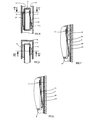
- Figure 1 is a sectional view of a roller shutter equipped with a generator according to the invention.
- Figure 4 shows the detail, in vertical section along IV-IV of Figure 5, of an exemplary embodiment of the vibrating element and the wiper.
- FIG. 5 is a sectional view along V-V of FIG. 4.
- FIGS 6 and 7 show two other embodiments of the vibrating element.
- FIG. 8 represents the diagram of the signal processing means and of the means for controlling the rolling stock shown in FIG. 1.
- FIG. 9 represents a first embodiment of the reference signal generator.
- FIG. 10 shows a simplified embodiment of the reference signal generator.
- FIG. 11 represents the main program of the control means.
- FIG. 12 represents a variant of a sub-program for controlling the shutter shutter.
- FIG. 14 represents the decoding circuit of an alternative embodiment with two sensors.
- FIG. 16 represents a variant of the main program for the case of transmission of signals with periodic variations.
- Figure 17 shows the variation counting routine.
- Figure 18 shows the alarm routine.
- FIG. 19 represents a modification of the program of FIG. 16 making it possible to obtain intermediate stop positions.
- FIG. 20 represents the counting subroutine of the variant represented in FIG. 19.
- the vibration sensor can be of the accelerometer or piezoelectric or ferroelectric shock detector type, of micro-machined silicon with integrated processing electronics, for example a sensor sold by MURATA under the trade name PKS-4A.
- the signals emitted by the sensor 7 are processed by a control device 13 controlling the motor of the winding axis 4.
- the installation is completed by a remote control 14, connected galvanically or not to the control electronics 13 and comprising keys for controlling the raising, lowering and stopping of the shutter.
- FIG. 3 represents an alternative embodiment of FIG. 2, in which the stop 6 is removed and the vibrating element 9 is shorter.
- the upper position of the shutter is reached when the wiper leaves the vibrating element 9. This execution allows the shutter to stop smoothly, without sudden pulling. She is particularly advantageous in the case of fragile roller shutters.
- FIGS 4 and 5 show, in more detail, an embodiment and mounting of the wiper 11. It is fixed by riveting, welding or clipping at a point 17 inside the last tubular blade 8 of the shutter rolling and passes through this blade through a slot 18.
- the wiper 11 has a curved end 11a in contact with the vibrating element formed here by the slide 3 itself.
- the vibrating element consists of a rough blade 19 fixed to the slide by means of an adhesive 20.
- the rough blade 19 is replaced by a blade 21 having a serrated profile 22.
- This profile could also be serrated.
- Such a profile makes it possible to obtain a periodic variation in the amplitude of the vibrations, each variation corresponding to a tooth or a niche.
- the counting of these variations makes it possible to determine the position of the wiper, that is to say the position of the roller shutter.
- the control device 13 is shown diagrammatically in FIG. 8. It consists of processing electronics 23 and control electronics 24 for controlling the motor 25.
- the comparator 28 has the function of comparing the value of the signal received from the amplifier-demodulator 26 to that received from the reference generator 27 and of delivering a logic signal (0 or 1) according to the relative level of the compared values. In the particular case, the comparator 28 delivers the signal 1 when the value of the signal picked up is greater than the reference value.
- the microprocessor 29 further includes a fourth DPI input (intermediate position request), a position counter 291 and a reaction time counter 292, a memory 294 for storing the alarm reaction time or the minimum position variation for triggering an alarm and a memory 295 for storing the value of the position counter.
- a fourth DPI input intermediate position request
- a position counter 291 for storing the alarm reaction time or the minimum position variation for triggering an alarm
- a memory 295 for storing the value of the position counter.
- the control device 13 further comprises a stabilized supply 32 for supplying various components.
- the execution mode corresponding to the program represented in FIG. 11 includes two end of travel or obstacle indicators, up and down FCM and FCD positioned high by the stop subroutines, respectively in the direction of ascent (M) and descent (D) and reset to zero when moving in the opposite direction.
- This embodiment therefore makes it possible to stop at the end of the race at a high, low stopping point and in the event of obstacles, by detection of the interruption of the vibrations, as well as the detection of an intrusion attempt by appearance. vibrations.
- the alarm subroutine could be deleted.
- the Up and Down stop subroutines of figure 11 are replaced by the subroutine according to figure 12 and the microprocessor includes a memory 293 storing the stop reaction time value and a stop reaction time counter 292.
- the instruction 33 increments the stop reaction time counter 292.
- the following instruction is a test instruction 34 which compares the counted value with the stored value. If the counted value is greater than the memorized value, then only the SM and SD outputs are set to zero by the following instruction and the program loops. Simultaneously, instruction 35 resets counter 292 to 0.
- the program loops without issuing a stop command.
- instruction 36 increments counter 292 and instruction 37 compares the counted value with the value stored in memory 294. If the counted value is greater than the stored value, the SA output goes to 1 and a alarm is triggered. Simultaneously, instruction 38 resets the counter to 292 at 0.
- This embodiment makes it possible to avoid stopping or triggering alarms resulting from false faults, such as those caused by shocks, hard points in the slide, fugitive obstacles.
- the safety-stop device which has just been described leads to stopping the descent in the non-stacked blade position (so-called "openwork” position if the wiper has been arranged on the lower blade of the closure (blade 8).
- Another interesting embodiment consists in using two vibration sensors, one per slide. This embodiment makes it possible to define an intermediate position and / or several operating zones.
- the intermediate position here corresponds to the "openwork" position described above.
- a first wiper A is disposed on the lower blade 8 of the shutter, on the side of a first slide 3A (or of the corresponding vibration element).
- the second wiper B is placed on the side of the slide 3B (or of the corresponding vibration element) and it is placed on the blade penetrating the slide 3B (or coming into contact with the corresponding vibration element) when the flap arrives in the intermediate position.
- FIG. 14 represents the decoding of the four usable zones.
- SLA and SLB represent the signals delivered by each of the sensors in the presence of vibrations. The algorithms for exploiting this information are within the reach of those skilled in the art.
- FIG. 15 represents a particularly simple embodiment of the logic of the control device 13 indicated by the control algorithms of FIGS. 11 and 12 (alarm function excluded).
- This embodiment uses wired logic and requires only three current integrated circuits (for example TL 084, MC 14538 B, 74 C 74) possibly replaceable by a single circuit of the ASIC type.
- a unipolar established power supply 71 supplies a supply voltage + Vcc to the entire assembly. This voltage is divided by two to allow, at the output of a follower 72, a potential reference used as virtual ground for the analog part of the circuit.
- the piezoelectric detector 7 sees its output signal amplified by two operational amplifiers 74 and 75, with elimination of any continuous components.
- the amplified signal is applied to the input (+) of an operational amplifier 76 which is used in comparator mode.
- the output levels of comparator 76 then correspond to the saturation voltages of the operational amplifier and are close enough to + Vcc and 0 to attack CMOS type logic.
- Each vibration detected and amplified causes the output of the comparator 76 (equivalent to the signal SL of the programmed execution) to go to the "high" state as long as the amplified level is greater than a reference voltage applied to the input ( -) of comparator 76 by a resistive divider bridge.
- Amplifiers 72, 73, 74, 75, 76 belong to the same integrated circuit (for example TL084).
- the output of comparator 76 is applied to a monostable 77 (retriggerable one shot, for example MC 14538 B) whose output Q * goes to the low state for a fixed duration T when the input A undergoes a transition from the "low” state to the "high” state.
- This duration T is always counted from the last upward transition of the input if several pulses are applied to it.
- the duration T is chosen so as to be greater than the maximum time separating two pulses during the movement of the wiper on the vibration element.
- the output Q * therefore returns to the high state only if the vibrations disappear for a duration greater than T.
- two flip-flops 78 and 79 record the state present on the Data input. This state is taken from the collectors of two transistors 80 and 81. One or the other of the transistors is conductive in the event of movement. In the Up SM direction, the transistor 80 is conductive. In the SD down direction, transistor 81 is conductive. The collector of the conducting transistor is in the "low” state while the collector of the blocked transistor is in the "high” state.
- the circuit further comprises a switch 84 with three positions: DD, STOP (intermediate position) and DM controlled by the remote control 14.
- transil diodes 85 and 86 designate transil diodes or other protection devices intended to avoid induced variations in potential of high amplitude on the emitter of a transistor not connected to ground by the switch 84.
- the senor 7 is designed to emit at least one signal of higher value on the passage of each tooth or slot and the reference value supplied by the reference generator 27 of the processing electronics 23 is fixed so as to that the processing electronics does not deliver a 0 or 1 signal on the SL output until each reception of this higher value signal.
- These signals are counted by the position counter 291 of the microprocessor 29 and the number of signals transmitted is stored in memory 295.
- the program according to FIG. 16 comprises the following instructions: a request and initialization (DI) instruction 39, an instruction 40 for scanning the DD input (descent request), an instruction 41 for resetting the position counter 291 to zero, a instruction 42 for initializing a counting subroutine, an instruction 43 for copying the value counted by the counter 291 into the position memory 295, an instruction 44 for reading the position counter 291, an instruction 45 for comparing from the counted value to the value stored in 295, an instruction 46 for initializing the counting subroutine, an instruction 47 for comparing the counted value with the stored value, an instruction 48 for initializing a subroutine ascent, an instruction 49 for testing the value counted by the position counter 291 and an instruction 50 for initializing the counting subroutine. Instructions 42, 46 and 50 initialize the same counting routine.
- DI request and initialization
- Instruction 45 tests whether the value counted is greater than or equal to the value stored in the position memory 295.
- Instruction 48 allows the shutter to be raised if it has encountered an obstacle.
- Instruction 49 tests whether the counted value is less than or equal to 0.
- This embodiment makes it possible, in the case of the descent of the roller shutter, to distinguish the arrival in the low position (closed position) from the arrival on an obstacle and, in this case, to activate the subroutine of ascent 48 to clear the obstacle.
- the counting and alarm subroutines may or may not include instructions intended to prevent the sending of a stop or alarm order, respectively, before the reception of a certain number of signals.
- the counting and alarm subroutines are developed in Figures 17 and 18 respectively.
- the alarm subroutine is optional.
- the alarm subroutine represented in FIG. 18 includes an instruction 55 for incrementing an alarm reaction time counter, an instruction 56 testing whether the reaction time counted is greater than the stored time, an instruction 57 for resetting the alarm reaction time counter, an instruction 58 for incrementing a counter for variation of the minimum alarm position, an instruction 59 testing whether the value counted by the mini alarm position variation counter is greater than or equal to a value stored in memory 294 and an instruction 60 for resetting the mini alarm position variation counter to zero.
- Instructions 55 and 56 can be deleted if the introduction of a reaction time is dispensed with.
- This embodiment makes it possible, as in the initial embodiment, to avoid stops or alarms resulting from false faults.
- the characteristic position signals obtained by means of a toothed or grooved vibrating element, as described in the previous embodiment, can be used to determine intermediate positions of the roller shutter.
- the program represented in FIG. 16 is supplemented by the subroutines represented in FIGS. 19 and 20.
- the subroutine shown in Figure 19 is an intermediate position request subroutine. It includes an instruction 61 for testing the state of the DPI input (intermediate position request), a test instruction 62 testing whether the value of counted signals is greater than the value stored in the memory for storing the signal number corresponding to an intermediate position, a test instruction 63 testing whether the counted value is less than the stored value and an instruction 64 initializing a DPI counting subroutine (request for intermediate position). Instructions 65 and 66 can be deleted if the introduction of a reaction time is dispensed with.
- DPI 1 (intermediate position request)
- the program continues with the test instruction 62 which tests whether the number of signals counted is greater than the stored number counted from the high position. If the counted value is not greater than the memorized value, the program continues with the test instruction 63. If 63 tests that the counted value is less than the memorized value, which means that the wiper is above from the desired intermediate position, the SD output then changes to 1 and the program continues with the DPI counting routine, as shown in Figure 20.
- instruction 62 tests that the counted value is greater than the stored signal number, this means that the wiper is below the intermediate position.
- the output SM is set to 1 and the instruction 64 ′ calls a DPI counting subroutine analogous to the subroutine represented in FIG. 20, but without the ascent subroutine 67 since there is (already) an order climb.
- This embodiment allows the closure to be automatically stopped in a position located between the extreme positions and is particularly advantageous, for example, for stopping a rolling shutter in the open position, that is to say in a low position in which the shutter blades are not stacked on top of each other.
Landscapes
- Engineering & Computer Science (AREA)
- Structural Engineering (AREA)
- Architecture (AREA)
- Civil Engineering (AREA)
- Operating, Guiding And Securing Of Roll- Type Closing Members (AREA)
- Paper (AREA)
- Fuel-Injection Apparatus (AREA)
- Portable Nailing Machines And Staplers (AREA)
- Input Circuits Of Receivers And Coupling Of Receivers And Audio Equipment (AREA)
- Eye Examination Apparatus (AREA)
- Power-Operated Mechanisms For Wings (AREA)
- Preliminary Treatment Of Fibers (AREA)
- Shutters For Cameras (AREA)
- Measurement Of Mechanical Vibrations Or Ultrasonic Waves (AREA)
Claims (19)
- Vorrichtung zum Erzeugen von charakteristischen Signalen der Verschiebung eines Verschlussmittels, wie Fensterläden, Markisen oder Türen, dadurch gekennzeichnet, dass sie ein Schleiforgan (11), welches zur Befestigung an dem Verschlussmittel geeignet ist, und ein festes, starres Element (3; 16, 19; 21) aufweist, das dazu geeignet ist, durch das Schleiforgan in Vibrationen versetzt zu werden, und das sich über wenigstens die Länge des Verschiebungsweges des Verschlussmittels erstreckt, derart, dass das Schleiforgan während der Verschiebung des Verschlussmittels an dem starren Element schleift, und dass ein Vibrationsmessfühler (7) vorgesehen ist, welcher starr an dem erwähnten vibrierenden starren Element montiert ist und ein charakteristisches Signal dieser Vibrationen liefert.
- Vorrichtung nach Anspruch 1, dadurch gekennzeichnet, dass die Oberfläche des festen starren Elements, das sich in Kontakt mit dem Schleiforgan befindet, gezahnt (21) oder gerippt ist, derart, dass Vibrationen entstehen, deren Stärke sich periodisch ändert.
- Vorrichtung nach Anspruch 1 oder 2, dadurch gekennzeichnet, dass das vibrierende starre Element aus einer Gleitschiene oder einer Führungsschiene des Verschlussmittels besteht.
- Vorrichtung nach Anspruch 1 oder 2, dadurch gekennzeichnet, dass das vibrierende starre Element (16, 19; 21) an einer Gleitschiene oder Führungsschiene des Verschlussmittels befestigt ist.
- Motorisierte Schliessvorrichtung, dadurch gekennzeichnet, dass sie eine Vorrichtung zur Erzeugung von Signalen gemäss einem der Ansprüche 1 bis 4 und ausserdem elektronische Mittel (23) zur Verarbeitung des vom Vibrationsmessfühler (7) abgegebenen Signals sowie Mittel zur Steuerung (24) des oder der Motoren (25) zum Antrieb des Verschlussmittels als Funktion der von den Signalverarbeitungsmitteln erhaltenen Befehle aufweist.
- Schliessvorrichtung nach Anspruch 5, mit einem zwei Wicklungen aufweisenden Motor (25) zum Antrieb des Verschlussmittels im Sinne des Schliessens und des Oeffnens, dadurch gekennzeichnet, dass die Signalverarbeitungsmittel (23) einen Signal-Verstärker/Modulator (26), einen Bezugsgenerator (27), der einen Bezugswert liefert, und ein Vergleichsglied (28) aufweisen, auf welches das demodulierte Signal und der Bezugswert gegeben werden, dass dieses Vergleichsglied ein logisches Signal (0,1) entsprechend der relativen Lage der verglichenen Werte liefert, und dass die Mittel zur Steuerung einen Mikroprozessor (29) aufweisen, der ein Hauptprogramm (Figur 11), Eingänge für Aufwärts (DM), für Abwärts (DD), für Stop (DS), Ausgänge für Aufwärts (SM) und für Abwärts (SD) sowie einen Eingang (SL) aufweist, der an den Ausgang des Vergleichsglieds angeschlossen ist und dessen Hauptfunktion darin besteht, die Ausgänge für Aufwärts (SM) und für Abwärts (SD) auf 0 zu bringen, wenn das vom Vergleichsglied empfangene Signal gleich 0 ist, und dass ein Leistungsumschaltorgan (30) vorgesehen ist, das an jede der Motorwicklungen über die Aufwärts- und Abwärts-Ausgänge und an die Aufwärts- und Abwärts-Ausgänge des Mikroprozessors angeschlossen ist und dessen Funktion darin besteht, die Speisung an den Aufwärts- und Abwärts-Ausgängen (M, D) des Umschaltorgans zu unterbrechen, wenn die Aufwärts- und Abwärts-Ausgänge des Mikroprozessors gleich 0 sind.
- Schliessvorrichtung nach Anspruch 6, dadurch gekennzeichnet, dass der Mikroprozessor (29) ausserdem einen Speicher zur Speicherung der Reaktionszeit und einen Zähler zum Zählen der Reaktionszeit aufweist und dass das Hauptprogramm durch ein Unterprogramm (Figuren 12 und 13) vervollständigt ist, welches zu prüfen erlaubt, ob die Aenderung des logischen Werts am Ausgang (SL) des Vergleichsglieds (28) vor der Abgabe eines Befehls zum Anhalten des Motors und/oder eines Alarms eine bestimmte Zeitlang bestehen bleibt.
- Schliessvorrichtung nach Anspruch 6, dadurch gekennzeichnet, dass die Oberfläche (22) des vibrierenden starren Elements, das sich in Kontakt mit dem Schleiforgan befindet, geriffelt oder gezahnt ist, derart, dass eine Vibration entsteht, deren Amplitude beim Vorbeigang jeder Rille oder jedes Zahns variiert, dass der Messfühler (7) dazu eingerichtet ist, ein Signal abzugeben, dessen Amplitude als Funktion der Vibrationsamplitude variiert, dass der erwähnte Bezugswert derart festgesetzt ist, dass das Vergleichsglied (28) nur bei jeder Aenderung der Amplitude des vom Messglied ausgesandten Signals ein logisches Signal (0,1) liefert, und dass der Mikroprozessor (29) ausserdem einen Zähler, der die Zustandsänderungen am Ausgang des Vergleichsgliedes zählt, und einen Speicher aufweist, der die Anzahl der Zustandsänderungen speichert, die gezählt werden, während das Verschlussmittel seine gesamte Verschiebungslänge durchläuft, und dass Mittel zum Vergleich der Anzahl der gezählten Zustandsänderungen während der Verschiebung des Verschlussmittels mit der im Speicher gespeicherten Anzahl vorgesehen sind, derart, dass eine Unterscheidung zwischen der Ankunft in der Schliessstellung und dem Auftreffen auf ein Hindernis (7, 6) gemacht wird und dass im letzten Falle eventuell ein Unterprogramm der teilweisen Wiederaufwärtsbewegung aktiviert wird.
- Schliessvorrichtung nach Anspruch 8, dadurch gekennzeichnet, dass der Mikroprozessor (29) ausserdem einen Zähler (292) zum Zählen der Reaktionszeit und einen Speicher (294) zum Speichern eines Werts der Reaktionszeit aufweist und dass das Hauptprogramm durch ein Unterprogramm (Figur 17) vervollständigt ist, das zu prüfen erlaubt, ob die Aenderung des logischen Werts am Ausgang (SL) des Vergleichsglieds vor dem Aussenden eines Befehls zum Anhalten eine bestimmte Zeitlang bestehen bleibt.
- Schliessvorrichtung nach Anspruch 8 oder 9, dadurch gekennzeichnet, dass sie ein Alarmglied (31) aufweist und dass der Mikroprozessor ausserdem einen Speicher zum Speichern einer bestimmten Anzahl von Signalen (SL) und einen Alarmsignalzähler aufweist und dass das Programm (Figur 16) durch ein Alarm-Unterprogramm (Figur 18) vervollständigt ist, das gewährleistet, dass der Alarm nur dann ausgelöst wird, wenn der gezählte Wert grösser als der gespeicherte Wert ist.
- Schliessvorrichtung nach einem der Ansprüche 8, 9 oder 10, dadurch gekennzeichnet, dass die Mittel zum Steuern (24) ausserdem einen Speicher zum Speichern einer Signalnummer, die dem Zustand des Zählers entspricht, wenn die Schliessvorrichtung eine Zwischenposition einnimmt, und einen Eingang zum Abfragen der Zwischenposition (DPI) aufweisen und dass das Programm ausserdem ein Unterprogramm der Zwischenpositionsabfragung (Figur 19) und ein Unterprogramm der Signalzählung (Figur 20) umfasst, derart, dass das Anhalten der Schliessvorrichtung in der Zwischenposition ermöglicht wird.
- Schliessvorrichtung nach Anspruch 11, dadurch gekennzeichnet, dass das Unterprogramm der Zählung der Zwischenpositionsabfrage (Figur 20) ausserdem ein Unterprogramm für die Wiederaufwärtsbewegung (67) aufweist.
- Vorrichtung zum Steuern einer motorisierten Schliessvorrichtung mit geführter Bewegung, die Positionsmarkierungen (22), Mittel zum Erfassen (21, 11 (7, 13) dieser Positionsmarkierungen, einen Zähler (291) zum Zählen der von der Schliessvorrichtung bei ihrer Verschiebung passierten Positionsmarkierungen, einen Speicher (295), in welchem bestimmte Positionen gespeichert werden, und eine logische Verarbeitungseinheit (24) zum Adressieren von Befehlen an den Motor (25) als Funktion der gezählten Positionsmarkierungen und der gespeicherten Positionen aufweist, dadurch gekennzeichnet, dass die Mittel zum Erfassen ein zur Befestigung an dem Verschlussmittel geeignetes Schleiforgan (11) und ein festes starres Element (3; 9, 19; 21) aufweisen, das dazu geeignet ist, durch das Schleiforgan in Vibrationen versetzt zu werden und welches sich über wenigstens die Länge des Verschiebungswegs des Schliessmittels erstreckt, derart, dass das Schleiforgan an dem starren Element während der Verschiebung des Schliessmittels reibt, und dass ein Vibrationsmessfühler (7) vorgesehen ist, der starr an dem erwähnten vibrierenden starren Element montiert ist und ein für diese Vibrationen charakteristisches Signal liefert, und dass elektronische Mittel zur Verarbeitung (23) des vom Messfühler abgegebenen Signals vorhanden sind.
- Motorisierte Schliessvorrichtung nach einem der Ansprüche 5, 6 oder 7, deren Verschlussmittel aus einem Rolladen besteht, dessen Lamellen in Schliessstellung aneinander gelegt oder im Abstand voneinander angeordnet werden können, dadurch gekennzeichnet, dass sie ein erstes Schleiforgan, das fest mit der unteren Lamelle (8) verbunden ist, und ein zweites Schleiforgan aufweist, das fest mit einer oberen Lamelle verbunden ist, welche in die Gleitschiene (3) eingreift und mit dem vibrierenden Element (3; 9; 19) gerade, bevor die untere Lamelle (8) am Anschlag für die Schliessstellung anlangt, in Kontakt kommt, derart, dass der Motor erst gestoppt wird, nachdem sich alle in der Gleitschiene befindlichen Lamellen aneinandergelegt haben.
- Motorisierte Schliessvorrichtung nach einem der Ansprüche 5, 6 oder 7, deren Verschlussmittel ein Rolladen ist, dessen Lamellen in zwei Gleitschienen geführt sind, dadurch gekennzeichnet, dass sie ein vibrierendes Element und einen Messfühler in jeder der Gleitschienen, sowie ein erstes, fest mit der unteren Lamelle (8) verbundenes Schleiforgan, welches an einem der vibrierenden Elemente derart schleift, dass ein erstes Signal (SLA) geliefert wird, und ein zweites Schleiforgan aufweist, das mit einer Zwischenlamelle fest verbunden ist, die in die Gleitschienen eingreift und mit dem anderen vibrierenden Element in dem Augenblick in Berührung kommt, an welchem die untere Lamelle (8) in eine Zwischenposition gelangt, wobei ein zweites Signal (SLB) geliefert wird, und dass die elektronischen Steuermittel eine Dekodierungsschaltung (Figur 14) mit vier Ausgängen aufweisen, die es erlauben, vier Zustände zu unterscheiden, welche den vier Kombinationen der Zustände der Ausgänge der Messfühler entsprechen.
- Schliessvorrichtung nach Anspruch 15 mit einem zwei Wicklungen aufweisenden Motor (25) für die beiden Drehrichtungen, die der Abwärts- und der Aufwärtsbewegung des Rolladens entsprechen, und mit einer Steuerung, die einen Aufwärtsbefehl (SM=1) oder einen Abwärtsbefehl (SD=1) liefern kann, dadurch gekennzeichnet, dass die elektronischen Mittel zur Steuerung ausserdem Mittel zum Speichern des vorangehenden Zustands der Ausgänge der Dekodierungsschaltung aufweisen, derart, dass bei der Abwärtsbewegung zwischen einem Halt infolge eines Hindernisses und einem Halt in der völlig geschlossenen Stellung, in der die Lamellen aneinander liegen, unterschieden werden kann.
- Motorisierte Schliessvorrichtung nach Anspruch 5, mit einem zwei Wicklungen aufweisenden Motor (25) für den Antrieb des Schliessmittels in Oeffnungs- und Schliess-Richtung, dadurch gekennzeichnet, dass die Mittel zur Verarbeitung des Signals des Messfühlers (7) eine Schaltung (71, 72), die eine Bezugsspannung liefert, eine Verstärkerschaltung (74, 75) und ein Vergleichsglied (76) aufweisen, welches das verstärkte Signal mit der Bezugsspannung vergleicht und dessen Ausgang, der einen Zustand "oben" und einen Zustand "unten" einnehmen kann, auf eine wiedereinschaltbare monostabile Kippstufe (22) gegeben wird, und dass der Ausgang Q* dieser monostabilen Kippstufe während einer festen Dauer (T), welche grösser als die maximale Zeit ist, die zwei Impulse während der Bewegung des Schleiforgans auf dem vibrierenden Element trennt, in den Zustand "unten" geschaltet wird, und erst wieder in den Zustand "oben" zurückkehrt, wenn die Vibrationen während einer Dauer, die grösser als die erwähnte feste Dauer (T) ist, verschwinden.
- Schliessvorrichtung nach Anspruch 17, dadurch gekennzeichnet, dass die Mittel zur Verarbeitung ausserdem zwei Kippstufen (78, 79) aufweisen, auf welche der Ausgang Q* der wiedereinschaltbaren monostabilen Kippstufe (77) gegeben wird, dass eine der Kippstufen (78) an eine Schaltung (80, 82, 84) angeschlossen ist, die eine Aufwärtsbewegung (SM) erfasst, und die andere Kippstufe (79) an eine Schaltung (81, 83, 84) angeschlossen ist, die eine Abwärtsbewegung erfasst, um einen Fehler in den Kippstufen durch einen bestimmten Zustand zu registrieren, d.h., wenn die Vibration aufhört, während der Motor in Aufwärts- oder Abwärtsbewegung aktiviert ist, wobei die erwähnten Schaltungen ausserdem derart ausgebildet sind, dass die Registrierung des Fehlers so lange aufrechterhalten bleibt, wie ein Befehl zur Bewegung im entgegengesetzten Sinne nicht gegeben worden ist.
- Schliessvorrichtungen nach Anspruch 18, dadurch gekennzeichnet, dass die erwähnten Schaltungen (80, 82, 84 und 81, 83, 84) jede einen Transistor (80, 81) aufweisen, deren Kollektoren an den betreffenden Eingang Data jeder der Kippstufen (78, 79) angeschlossen und deren Emitter jeweils an die beiden Klemmen (DD, DM) eines Steuerschalters (84) für die Steuerung der Aufwärts- und der Abwärtsbewegung des Fensterladens angeschlossen sind, wobei der eine oder der andere der Transistoren im Falle der Bewegungssteuerung leitend ist und ein in einer der Kippstufen registrierter Fehler bewirkt, die Leitung des entsprechenden Transistors zu sperren, und wobei dieser Sperrzustand solange aufrechterhalten bleibt, wie der andere Transistor nicht durch die Aenderung des Zustands des Schalters leitend geworden ist, d.h. durch das Auftreten eines Befehls zur Bewegung im entgegengesetzten Sinne.
Applications Claiming Priority (2)
| Application Number | Priority Date | Filing Date | Title |
|---|---|---|---|
| FR929206610A FR2691746B1 (fr) | 1992-06-01 | 1992-06-01 | Dispositif generateur de signaux caracteristiques du deplacement d'un moyen de fermeture. |
| FR9206610 | 1992-06-01 |
Publications (2)
| Publication Number | Publication Date |
|---|---|
| EP0573388A1 EP0573388A1 (de) | 1993-12-08 |
| EP0573388B1 true EP0573388B1 (de) | 1996-09-18 |
Family
ID=9430309
Family Applications (1)
| Application Number | Title | Priority Date | Filing Date |
|---|---|---|---|
| EP93810369A Expired - Lifetime EP0573388B1 (de) | 1992-06-01 | 1993-05-19 | Einrichtung zur Erzeugung charakteristischer Signale der Verschiebung eines Verschlussmittels |
Country Status (6)
| Country | Link |
|---|---|
| EP (1) | EP0573388B1 (de) |
| JP (1) | JPH0642278A (de) |
| AT (1) | ATE143093T1 (de) |
| DE (1) | DE69304799T2 (de) |
| ES (1) | ES2048723T1 (de) |
| FR (1) | FR2691746B1 (de) |
Cited By (2)
| Publication number | Priority date | Publication date | Assignee | Title |
|---|---|---|---|---|
| US7319391B2 (en) | 2001-07-11 | 2008-01-15 | Somfy Sas | Centralised security closure |
| US7504792B2 (en) | 2006-01-23 | 2009-03-17 | Somfy Sas | Method of configuring a control unit of an actuator |
Families Citing this family (12)
| Publication number | Priority date | Publication date | Assignee | Title |
|---|---|---|---|---|
| FR2712348B1 (fr) * | 1993-11-12 | 1996-02-02 | Somfy | Dispositif générateur de signaux caractéristiques du déplacement d'un moyen de fermeture. |
| DE4440449C2 (de) * | 1994-11-14 | 1997-06-12 | Elero Antrieb Sonnenschutz | Verfahren und Vorrichtung zur Stillstandssteuerung von elektromotorisch betriebenen Rolläden oder dergleichen |
| FR2735812B1 (fr) * | 1995-06-21 | 1997-08-22 | Somfy | Dispositif d'enroulement motorise pour stores venitiens |
| CA2288652A1 (en) * | 1997-04-16 | 1998-10-22 | Nergeco | Security door with sliding panel |
| FR2762354B1 (fr) * | 1997-04-16 | 1999-05-21 | Nergeco Sa | Dispositif de securite pour porte a panneau coulissant |
| FR2819545B1 (fr) * | 2001-01-18 | 2003-08-15 | Bubendorff Volet Roulant | Volet roulant pourvu d'un dispositif de detection d'obstacle |
| FR2822885B1 (fr) * | 2001-03-28 | 2004-01-30 | Bubendorff Volet Roulant | Volet roulant pourvu de moyens aptes a detecter un choc |
| FR2822887B1 (fr) * | 2001-03-28 | 2004-01-30 | Bubendorff Volet Roulant | Volet roulant motorise a commande d'arret du moteur sur obstacle |
| CA2445365A1 (en) * | 2001-05-03 | 2002-11-14 | Techniku, Inc. | Control and motorization system |
| ITRM20090288A1 (it) * | 2009-06-08 | 2010-12-09 | Lince Italia S P A | Dispositivo anti intrusione, in particolare per serrande avvolgibili |
| FR2955888B1 (fr) * | 2010-02-04 | 2012-03-23 | Somfy Sas | Outil de reglage de fin de course. |
| DE102017108757A1 (de) * | 2017-04-25 | 2017-11-23 | Meißner GmbH Toranlagen | Rollgitter-Toranlage |
Family Cites Families (2)
| Publication number | Priority date | Publication date | Assignee | Title |
|---|---|---|---|---|
| DE3806733A1 (de) * | 1988-03-02 | 1989-09-14 | Elero Antrieb Sonnenschutz | Anordnung zur ueberwachung und steuerung von rollaeden und dergleichen |
| FR2657646B1 (fr) * | 1990-01-26 | 1992-04-30 | Somfy | Dispositif de securite pour volet roulant motorise. |
-
1992
- 1992-06-01 FR FR929206610A patent/FR2691746B1/fr not_active Expired - Fee Related
-
1993
- 1993-05-19 AT AT93810369T patent/ATE143093T1/de not_active IP Right Cessation
- 1993-05-19 EP EP93810369A patent/EP0573388B1/de not_active Expired - Lifetime
- 1993-05-19 ES ES93810369T patent/ES2048723T1/es active Pending
- 1993-05-19 DE DE69304799T patent/DE69304799T2/de not_active Expired - Fee Related
- 1993-05-31 JP JP5128634A patent/JPH0642278A/ja not_active Withdrawn
Cited By (2)
| Publication number | Priority date | Publication date | Assignee | Title |
|---|---|---|---|---|
| US7319391B2 (en) | 2001-07-11 | 2008-01-15 | Somfy Sas | Centralised security closure |
| US7504792B2 (en) | 2006-01-23 | 2009-03-17 | Somfy Sas | Method of configuring a control unit of an actuator |
Also Published As
| Publication number | Publication date |
|---|---|
| DE69304799T2 (de) | 1997-04-03 |
| EP0573388A1 (de) | 1993-12-08 |
| DE69304799D1 (de) | 1996-10-24 |
| JPH0642278A (ja) | 1994-02-15 |
| FR2691746B1 (fr) | 1994-08-05 |
| ES2048723T1 (es) | 1994-04-01 |
| FR2691746A1 (fr) | 1993-12-03 |
| ATE143093T1 (de) | 1996-10-15 |
Similar Documents
| Publication | Publication Date | Title |
|---|---|---|
| EP0573388A1 (de) | Einrichtung zur Erzeugung charakteristischer Signale der Verschiebung eines Verschlussmittels | |
| EP0439422B1 (de) | Sicherheitseinrichtung für motorisierte Rolladen | |
| EP0833435B1 (de) | Steuerungsvorrichtung für einen einen Vorhang oder ein Rolladen antreibenden Asynchronmotor | |
| EP2216478B1 (de) | Anordnung zur Erkennung eines Hindernisses zwischen der Schwelle einer Gebäudeöffnung und dem Endstück einer motorisierten Abschirmung | |
| EP0784146B1 (de) | Motorbetriebene Schliess- oder Sonnenschutzeinrichtung | |
| FR2851361A1 (fr) | Actionneur de porte automatique | |
| FR2680437A1 (fr) | Montage pour surveiller des elements de fermeture entraines par un moteur electrique. | |
| EP0604289A1 (de) | Stromversorgungsverfahren und -vorrichtung für einen elektrischen Motor, insbesondere zum Antrieb eines Scheibenwischers eines Automobils | |
| FR1465742A (fr) | Appareil électrique servant à lever et à abaisser un volet roulant, tel une jalousie | |
| EP0671542B1 (de) | Mit einem elektrischen Motor angetriebenen Vorrichtung mit Mitteln zum Messen der Bewegung eines angetriebenen Körpers | |
| EP3292262B1 (de) | Verfahren zur konfigurierung und steuerung des betriebs einer motorisierten antriebsvorrichtung für eine heimautomatisierungseinheit sowie zugehörige einheit und motorisierte antriebsvorrichtung | |
| FR3115555A1 (fr) | Procédé de commande en fonctionnement d’un dispositif d’occultation et dispositif d’occultation associé | |
| FR2854192A1 (fr) | Procede pour faire fonctionner un moteur utilise pour deplacer une barriere mobile et appareil pour la commande de ce moteur | |
| CH645864A5 (fr) | Dispositif d'entrainement d'un element souple autour d'une barre d'enroulement. | |
| EP0966085A1 (de) | Steuereinrichtung zur Ausschaltung einer motorisierten Verdunkelungseinrichtung | |
| EP0552338B1 (de) | Sicherungssystem für automatische türen | |
| FR3069008A1 (fr) | Fenetre coulissante pour un batiment et installation domotique comprenant une telle fenetre coulissante, ainsi que procede de commande associe | |
| EP0819204A1 (de) | Hubtor mit sicherheitssystem | |
| EP0502773A2 (de) | Steuerungsanordnung für einen Motor, insbesondere für den Antrieb von Aufzugstüren | |
| EP3530857B1 (de) | Betriebssteuerungsverfahren einer motorisierten antriebsvorrichtung eines fensters für ein gebäude, entsprechendes fenster und entsprechende haustechnikanlage | |
| EP3470616B1 (de) | Verfahren zur automatischen regulierung einer mit einem blockiersystem ausgestatteten rollladenanlage | |
| EP0678643B1 (de) | Kraftfahrzeugfensterheber mit Einklemmschutz und verringerter Anzahl von Anschlussdrähten | |
| FR3106781A1 (fr) | Dispositif d’actionnement destiné à l’ouverture et à la fermeture assistée d’un ouvrant de véhicule | |
| EP3805503B1 (de) | Verfahren zur steuerung der funktion eines motorischen antriebs eines gebäudeschiebefensteres, in verbindung mit einem fenster und einem hausautomationssystem | |
| EP0533625B1 (de) | Sicherheitsvorrichtung für Rolltore oder Rolläden |
Legal Events
| Date | Code | Title | Description |
|---|---|---|---|
| PUAI | Public reference made under article 153(3) epc to a published international application that has entered the european phase |
Free format text: ORIGINAL CODE: 0009012 |
|
| AK | Designated contracting states |
Kind code of ref document: A1 Designated state(s): AT BE CH DE ES GB IT LI NL SE |
|
| REG | Reference to a national code |
Ref country code: ES Ref legal event code: BA2A Ref document number: 2048723 Country of ref document: ES Kind code of ref document: T1 |
|
| 17P | Request for examination filed |
Effective date: 19940310 |
|
| 17Q | First examination report despatched |
Effective date: 19951114 |
|
| GRAH | Despatch of communication of intention to grant a patent |
Free format text: ORIGINAL CODE: EPIDOS IGRA |
|
| GRAH | Despatch of communication of intention to grant a patent |
Free format text: ORIGINAL CODE: EPIDOS IGRA |
|
| GRAA | (expected) grant |
Free format text: ORIGINAL CODE: 0009210 |
|
| AK | Designated contracting states |
Kind code of ref document: B1 Designated state(s): AT BE CH DE ES GB IT LI NL SE |
|
| PG25 | Lapsed in a contracting state [announced via postgrant information from national office to epo] |
Ref country code: NL Free format text: LAPSE BECAUSE OF FAILURE TO SUBMIT A TRANSLATION OF THE DESCRIPTION OR TO PAY THE FEE WITHIN THE PRESCRIBED TIME-LIMIT Effective date: 19960918 Ref country code: GB Effective date: 19960918 Ref country code: AT Effective date: 19960918 |
|
| REF | Corresponds to: |
Ref document number: 143093 Country of ref document: AT Date of ref document: 19961015 Kind code of ref document: T |
|
| REF | Corresponds to: |
Ref document number: 69304799 Country of ref document: DE Date of ref document: 19961024 |
|
| ITF | It: translation for a ep patent filed | ||
| PG25 | Lapsed in a contracting state [announced via postgrant information from national office to epo] |
Ref country code: SE Effective date: 19961218 |
|
| PG25 | Lapsed in a contracting state [announced via postgrant information from national office to epo] |
Ref country code: ES Free format text: LAPSE BECAUSE OF FAILURE TO SUBMIT A TRANSLATION OF THE DESCRIPTION OR TO PAY THE FEE WITHIN THE PRESCRIBED TIME-LIMIT Effective date: 19961229 |
|
| NLV1 | Nl: lapsed or annulled due to failure to fulfill the requirements of art. 29p and 29m of the patents act | ||
| GBV | Gb: ep patent (uk) treated as always having been void in accordance with gb section 77(7)/1977 [no translation filed] |
Effective date: 19960918 |
|
| PG25 | Lapsed in a contracting state [announced via postgrant information from national office to epo] |
Ref country code: LI Free format text: LAPSE BECAUSE OF NON-PAYMENT OF DUE FEES Effective date: 19970531 Ref country code: CH Free format text: LAPSE BECAUSE OF NON-PAYMENT OF DUE FEES Effective date: 19970531 |
|
| PGFP | Annual fee paid to national office [announced via postgrant information from national office to epo] |
Ref country code: BE Payment date: 19970711 Year of fee payment: 5 |
|
| PLBE | No opposition filed within time limit |
Free format text: ORIGINAL CODE: 0009261 |
|
| STAA | Information on the status of an ep patent application or granted ep patent |
Free format text: STATUS: NO OPPOSITION FILED WITHIN TIME LIMIT |
|
| 26N | No opposition filed | ||
| REG | Reference to a national code |
Ref country code: CH Ref legal event code: PL |
|
| PGFP | Annual fee paid to national office [announced via postgrant information from national office to epo] |
Ref country code: DE Payment date: 19980326 Year of fee payment: 6 |
|
| PG25 | Lapsed in a contracting state [announced via postgrant information from national office to epo] |
Ref country code: BE Free format text: LAPSE BECAUSE OF NON-PAYMENT OF DUE FEES Effective date: 19980531 |
|
| BERE | Be: lapsed |
Owner name: SOMFY Effective date: 19980531 |
|
| PG25 | Lapsed in a contracting state [announced via postgrant information from national office to epo] |
Ref country code: DE Free format text: LAPSE BECAUSE OF NON-PAYMENT OF DUE FEES Effective date: 20000301 |
|
| PG25 | Lapsed in a contracting state [announced via postgrant information from national office to epo] |
Ref country code: IT Free format text: LAPSE BECAUSE OF NON-PAYMENT OF DUE FEES;WARNING: LAPSES OF ITALIAN PATENTS WITH EFFECTIVE DATE BEFORE 2007 MAY HAVE OCCURRED AT ANY TIME BEFORE 2007. THE CORRECT EFFECTIVE DATE MAY BE DIFFERENT FROM THE ONE RECORDED. Effective date: 20050519 |