EP0573653A1 - Chalumeau coupeur a plasma - Google Patents
Chalumeau coupeur a plasma Download PDFInfo
- Publication number
- EP0573653A1 EP0573653A1 EP92906228A EP92906228A EP0573653A1 EP 0573653 A1 EP0573653 A1 EP 0573653A1 EP 92906228 A EP92906228 A EP 92906228A EP 92906228 A EP92906228 A EP 92906228A EP 0573653 A1 EP0573653 A1 EP 0573653A1
- Authority
- EP
- European Patent Office
- Prior art keywords
- nozzle
- end portion
- protection cap
- plasma
- passage
- Prior art date
- Legal status (The legal status is an assumption and is not a legal conclusion. Google has not performed a legal analysis and makes no representation as to the accuracy of the status listed.)
- Granted
Links
Images





Classifications
-
- H—ELECTRICITY
- H05—ELECTRIC TECHNIQUES NOT OTHERWISE PROVIDED FOR
- H05H—PLASMA TECHNIQUE; PRODUCTION OF ACCELERATED ELECTRICALLY-CHARGED PARTICLES OR OF NEUTRONS; PRODUCTION OR ACCELERATION OF NEUTRAL MOLECULAR OR ATOMIC BEAMS
- H05H1/00—Generating plasma; Handling plasma
- H05H1/24—Generating plasma
- H05H1/26—Plasma torches
- H05H1/32—Plasma torches using an arc
- H05H1/34—Details, e.g. electrodes, nozzles
-
- H—ELECTRICITY
- H05—ELECTRIC TECHNIQUES NOT OTHERWISE PROVIDED FOR
- H05H—PLASMA TECHNIQUE; PRODUCTION OF ACCELERATED ELECTRICALLY-CHARGED PARTICLES OR OF NEUTRONS; PRODUCTION OR ACCELERATION OF NEUTRAL MOLECULAR OR ATOMIC BEAMS
- H05H1/00—Generating plasma; Handling plasma
- H05H1/24—Generating plasma
- H05H1/26—Plasma torches
- H05H1/32—Plasma torches using an arc
- H05H1/34—Details, e.g. electrodes, nozzles
- H05H1/3436—Hollow cathodes with internal coolant flow
-
- H—ELECTRICITY
- H05—ELECTRIC TECHNIQUES NOT OTHERWISE PROVIDED FOR
- H05H—PLASMA TECHNIQUE; PRODUCTION OF ACCELERATED ELECTRICALLY-CHARGED PARTICLES OR OF NEUTRONS; PRODUCTION OR ACCELERATION OF NEUTRAL MOLECULAR OR ATOMIC BEAMS
- H05H1/00—Generating plasma; Handling plasma
- H05H1/24—Generating plasma
- H05H1/26—Plasma torches
- H05H1/32—Plasma torches using an arc
- H05H1/34—Details, e.g. electrodes, nozzles
- H05H1/3457—Nozzle protection devices
-
- H—ELECTRICITY
- H05—ELECTRIC TECHNIQUES NOT OTHERWISE PROVIDED FOR
- H05H—PLASMA TECHNIQUE; PRODUCTION OF ACCELERATED ELECTRICALLY-CHARGED PARTICLES OR OF NEUTRONS; PRODUCTION OR ACCELERATION OF NEUTRAL MOLECULAR OR ATOMIC BEAMS
- H05H1/00—Generating plasma; Handling plasma
- H05H1/24—Generating plasma
- H05H1/26—Plasma torches
- H05H1/32—Plasma torches using an arc
- H05H1/34—Details, e.g. electrodes, nozzles
- H05H1/3468—Vortex generators
-
- H—ELECTRICITY
- H05—ELECTRIC TECHNIQUES NOT OTHERWISE PROVIDED FOR
- H05H—PLASMA TECHNIQUE; PRODUCTION OF ACCELERATED ELECTRICALLY-CHARGED PARTICLES OR OF NEUTRONS; PRODUCTION OR ACCELERATION OF NEUTRAL MOLECULAR OR ATOMIC BEAMS
- H05H1/00—Generating plasma; Handling plasma
- H05H1/24—Generating plasma
- H05H1/26—Plasma torches
- H05H1/32—Plasma torches using an arc
- H05H1/34—Details, e.g. electrodes, nozzles
- H05H1/3478—Geometrical details
Definitions
- the present invention relates to a plasma torch utilized for a plasma cutting machine.
- the electrode is attached to a body of the torch, to which the nozzle is attached through a gas jetting port for jetting an operation gas by gyrating about a periphery of axes of an insulating member and the electrode.
- Portions of the nozzle, except for the front end including a nozzle orifice of the nozzle, are covered, and a nozzle cap for fixing the nozzle to the torch body is screwed with the torch body.
- the cooling water after cooling the electrode passes an cooling water passage formed inside the torch body, then through a space defined by the torch body, the nozzle and the nozzle cap to cool the nozzle and then returns again to the cooling water passage formed to the torch body.
- a metallic nozzle protection cap electrically insulated from the nozzle is provided for protecting the nozzle front end portion, and also, the gas cooling the nozzle passes, as it is, the space between the nozzle and the nozzle cap to thereby blow off the blown-up fused metal.
- This nozzle protection method is disclosed in U.S. Patent No. 4861962 (Hiper: Filed on August 29, 1989).
- Japanese Patent Laid-open Publication No. 53-119753 discloses a plasma welding torch having a structure in which a metallic nozzle cap electrically insulated from the nozzle is mounted to the periphery of the nozzle and a secondary gas is flown between the nozzle and the nozzle protection cap.
- a front side of a cut groove is wide and a rear side thereof is narrow, and for this reason, the cut surface does not provide a perpendicular surface and has an inclination.
- a workpiece to be cut may be blown up by thermal deformation or in accordance with its supported condition, and it is difficult to avoid these phenomenon.
- the nozzle contacts the workpiece to be cut, the double-arc is generated, thus being difficult to avoid causing of danger for damaging the nozzle.
- a protection cap is adapted to the water-cooled nozzle.
- this function has a function for preventing the nozzle from contacting the workpiece to be cut, but this function is for shutting out a welding portion from atmosphere by the secondary gas, and since an opening of the protection cap is widely opened, there has no function for protecting the nozzle from the blow-up of the fused metal at the piercing time.
- a plasma arc of high temperature and high velocity is obtained by finely throttling the arc less than the nozzle diameter. If a more large amount of current passes to a nozzle having a small nozzle diameter, it becomes possible to cut the workpiece at a high cutting speed with a narrow cut groove width. However, as the electric current increases, there causes a double-arc generation phenomenon in which the current passes a metallic portion of the nozzle without passing the nozzle orifice, thus lowering the cutting ability and damaging the nozzle.
- the operation gas is forcibly gyrated and jetted around the electrode to finely throttle the arc, and the nozzle is water-cooled to thereby hardly cause the double-arc.
- the restriction of the plasma arc jetted from the nozzle is released and hence the plasma arc is swelled after the jetting-out from the nozzle, the cut groove width may be widened, thus providing a problem.
- the nozzle since the nozzle is not water-cooled, the cooling of the nozzle is insufficient and the double-arc is hence hardly caused and it is difficult to remarkably increase the electric current. Furthermore, although it is possible to further throttle the arc jetted from the nozzle by utilizing the secondary gas supplied so as to enclose the plasma arc by the nozzle protection cap, in the technology of the Second Prior Art, an opening is formed, other than the central opening for passing the secondary gas to enclose the plasma gas, for increasing the gas flow rate to cool the nozzle. Accordingly, it is impossible to independently control only the secondary gas surrounding the arc, and it is therefore difficult to achieve flow velocity or pressure sufficient for further throttling the plasma arc.
- the temperature of the nozzle protection cap rises due to the radiation from the plasma arc or the cut surface of the workpiece. Accordingly, in a case of exchanging consumable parts such as nozzle and electrode, it is required to effect the cooling for a time being by passing the secondary gas after the stopping of the arc or to exchange the consumable parts manually by utilizing such as hand gloves, thus being inconvenient and reducing workability at the time of exchanging the consumable parts.
- the electrode and the nozzle abut, in the fixed state, against respectively insulated metallic portions of the torch body, and power from a D.C. power source is supplied to the metallic portions, respectively.
- a cooling water passage connecting the metallic portion of the electrode side and the metallic portion of the nozzle side is formed for cooling the electrode and the nozzle.
- the torch body is constructed in a condition that the respective metallic portions are electrically insulated, but the respective metallic portions are connected with each other through the cooling water passage and the cooling water passes therethrough, so that a minute electric current passes through the cooling water.
- This minute electric current hardly affects on the generation of the arc, but corrosion on the metallic portion of the torch body gradually progresses by an electrochemical function due to this electric current.
- the electrode and the nozzle are water-cooled, there will be provided such a problem as that the torch becomes unusable before long.
- the present invention was conceived in view of the above matters and aims to provide a plasma arc capable of: achieving a function for effectively protecting a nozzle in a torch structure in which the nozzle is water-cooled to remarkably improve the life time of the nozzle; reducing a loss in time caused by the exchange of the nozzle and the running cost; performing a precise cutting operation with a fine cut groove width by rectifying the secondary gas by an insulator interposed in the secondary gas passage and then again throttling the plasma arc jetted from the nozzle 2; changing an inclination of a cut surface of the workpiece to a perpendicular direction by gyrating a gyration flow of the secondary gas in the same direction as the gyrating direction of the plasma arc; exchanging only the front end portion of the nozzle protection cap as a consumable part, thus being economical, because the nozzle protection cap can be separated into the front end portion and the base end portion; handing the base end portion of the nozzle protection cap without paying any specific attention to that portion
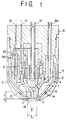
- the plasma torch according to the present invention has a structure in which a water-cooled electrode 1 is utilized and a plasma arc is generated between the electrode 1 and a workpiece 24 to be cut through an orifice 16 of a nozzle arranged so as to cover the electrode 1 through a plasma gas passage formed therebetween and the plasma torch is characterized in that a nozzle protection cap 5, 5a, 5b, 5c or 5d having, on its front end side, an opening opposing to the orifice 16 of the nozzle 2 is secured, in an electrically insulated state from the electrode 1 and the nozzle 2, to a portion outside a nozzle cap 4 so as to form an annular secondary gas passage 8 communicating with the opening between the nozzle protection cap and the nozzle cap 4, and an insulator 14 having an annular structure of an electrically insulating material and having a rectifying passage for rectifying a gas flow passing the secondary gas passage 8 is interposed in the secondary gas passage 8.
- the nozzle protection cap 5 is formed of a metal material having a good thermal conductivity.
- the insulator 14 has a rectangular section and the insulator 14 is fixedly engaged with stepped portions formed to an outer peripheral surface of the nozzle cap 4 and an inner peripheral surface of the nozzle protection cap.
- the nozzle protection cap 5b is composed of a front end portion 20 for protecting a front end portion of the nozzle 2 and a base end portion 19 secured to a torch body side, the front end portion 20 and the base end portion 19 being coupled detachably.
- flanged portions are provided for the front end portion 20 and the base end portion 19 constituting the nozzle protection cap 5b so as to be fitted to each other, or screws are formed to portions of the front end portion 20 and the base end portion 19 coupled with each other so that the front end portion 20 and the base end portion 19 are fitted to or screwed with each other in an easily detachable manner.
- the front end portion 20 among the front end portion 20 and the base end portion 19 constituting the nozzle protection cap 5b is formed of a metal material having a good thermal conductivity and the base end portion 19 thereamong is formed of a metal material being excellent in a mechanical strength.
- a gap 17 between the front end surface of the nozzle 2 and an inside surface of the opening of the nozzle protection cap 5, 5a or 5b has a dimension h of 0.5 - 1.5mm.
- a ratio ⁇ 2/ ⁇ 1 between an orifice diameter ⁇ 1 of the nozzle 2 and an opening diameter ⁇ 2 of the nozzle protection cap 5, 5a or 5b is set to 1.0 - 5.0.
- annular cooling water chamber 21 is formed inside the base end portion of the nozzle protection cap 5c so that the cooling water chamber 21 is communicated with a cooling water chamber 9 formed inside the electrode 1.
- the nozzle protection cap 5d is formed so as to have a bag-shape double wall structure having a space formed as a cooling water chamber 21a.
- a plasma gas flow-in passage 6a for introducing the plasma gas into a plasma gas passage 6 formed around the electrode 1 is formed, in an inclined manner with respect to an axis of the torch, for imparting a gyrating flow to the plasma gas
- the rectifying passage of the insulator 14 or 14a is formed to provide a spiral shape for imparting a gyrating flow to the secondary gas passing the rectifying passage in the same direction as the gyrating flow of the plasma gas, and a relationship between an orifice length L and the orifice diameter ⁇ 1 is satisfied with L/ ⁇ 1 ⁇ 2.
- a flow-in passage 25 communicating the cooling water chamber 9 on the side of the electrode 1 with the cooling water passage 10 on the side of the nozzle 2 is composed of a tube 26 formed of an electrically insulating material.
- the plasma torch having the embodiments described above attains the following functions and effects.
- the plasma arc jetted from the nozzle together with the plasma gas is jetted through the nozzle 2 and the nozzle orifice 16. At this moment, the secondary gas is jetted in a direction towards the plasma arc from the gap 17 and then the secondary gas is rectified by the insulator 14.
- the nozzle cap 4 and the nozzle protection cap 5 are axially aligned by the insulator and then coupled together.
- the nozzle protection cap can be cooled by providing the cooling water chamber to the base end portion 19a of the nozzle protection cap.
- the plasma gas is gyrated in the plasma gas passage 6 and the secondary gas is also gyrated in the plasma gas flow-in passage 6a in the same direction as that of the plasma gas.
- the electrochemical corrosion can be prevented by fitting the tube 26 formed of an electrically insulating material into a cooling water flow passage.
- the nozzle protection function can be effectively achieved also with respect to a torch structure in which the nozzle 2 is water-cooled, and accordingly, the life time of the nozzle 2 can be remarkably improved and the loss in time in the nozzle exchanging operation and the running cost can be reduced. Furthermore, by interposing the insulator in the secondary gas passage, the secondary gas is rectified by the insulator and the plasma arc jetted from the nozzle 2 is again throttled, thereby performing the precise cutting operation with a fine cut groove.
- the secondary gas can be gyrated in the same direction as the gyrating direction of the plasma arc by the rectifying passage of the insulator 14 or 14a, the inclination of the cut surface of the workpiece 24 can be changed to the perpendicular direction.
- the nozzle protection cap is separated into the front end portion and the base end portion, only the front end portion can be exchanged as a consumable part, thus being economical.
- reference numeral 1 denotes an electrode
- numeral 2 is a nozzle supported by a nozzle support member 3 at a portion opposing to the front end of the electrode 1
- numeral 4 denotes a nozzle cap covering the nozzle 1 except for the lower end portion thereof
- numeral 5 denotes a nozzle protection cap covering an outside of the nozzle cap 4.
- a plasma gas passage 6 communicated with the nozzle 2 from this periphery, and a cooling water passage 7 is formed between the nozzle 2 and the nozzle cap 4.
- a secondary gas passage 8 is formed between the nozzle cap 4 and the nozzle protection cap 5 so as to open to the front end side of the nozzle 2.
- the nozzle protection cap 5 is electrically insulated from the nozzle cap 4, and the nozzle 2 is supported also by the front end portion of the nozzle cap 4.
- a cooling water chamber 9 is formed inside the electrode 1 and this cooling water chamber 9 is, in one hand, communicated with the cooling water passage 7.
- a cooling water flow-in passage 10 is communicated with the cooling water chamber 9 and a cooling water flow-out passage 10a is, on the other hand, connected with the cooling water passage 7.
- a plasma gas flow-in passage 11 and a secondary gas flow-in passage 12 are connected respectively to the plasma gas passage 6 and the secondary gas passage 8.
- Reference numeral 13 denotes a torch body, which is electrically insulated from the electrode 1 and the nozzle 2.
- the nozzle protection cap 5 is screwed with this torch body 13.
- the secondary gas passage 8 formed between the nozzle cap 4 and the nozzle protection cap 5 provides a tapered annular shape, and an insulator 14 formed of an insulating material, also acting as a spacer, is mounted in the secondary gas passage 8 in an air-tight manner with respect to walls of the nozzle cap 4 and the nozzle protection cap 5.
- the insulator 14 is provided with a plurality of small openings 15 in the circumferential direction of the insulator so as to constitute rectifying passages communicating the downstream side and the upstream side of the insulator with each other.
- These small openings forming the rectifying passage may be formed as axial grooves 15a formed inner (or outer) surface of the insulator 14 as shown in Fig. 2(b) in place of small openings 15 shown in Fig. 2(a).
- the small openings 15 and the grooves 15a forming the rectifying passage may be formed so as to provide spiral shapes with respect to the axis of the insulator.
- the insulators 14 shown in Figs. 2(a) and 2(b) are formed with the tapered annular shapes in conformity with the tapered annular shape of the secondary gas passage 8 , but the shape of the insulator 14 is not limited to those shown in Figs. 2(a) and 2(b) and the insulator 14 may be formed so as to provide a rectangular shape in section as shown in Fig. 2(c), 2(d) or 2(e) for passing the rectified secondary gas along the axial direction.
- a ratio ( ⁇ 2/ ⁇ 1) between a diameter ⁇ 1 of an orifice 16 of the nozzle 2 and a diameter ⁇ 2 of an opening of the nozzle protection cap 5 is 1.0 to 5.0, and preferably 2.0 to 4.0, wherein in the case of ⁇ 2/ ⁇ 1 ⁇ 1.0, the front end of the nozzle protection cap 5 is deformed and damaged by the heat of the plasma arc and, moreover, the flow of the secondary gas is disturbed, and in the case of ⁇ 2/ ⁇ 1 > 5.0, the blow-up of the fused metal adheres to the nozzle 2 and the gap 17 between the lower surface of the nozzle 2 and the nozzle protection cap 5, causing the double-arc.
- the gap 17 has a gap dimension h of 0.5 to 1.5mm, wherein in the case of h ⁇ 0.5mm, the flow velocity of the secondary gas jet makes too fast to disturb the arc.
- the insulators 14 described above are formed of a synthetic resin such as fluoride series resin or ceramics material.
- the plasma arc generated from the electrode 1 is jetted, together with the plasma gas supplied to the plasma gas passage 6 formed around the electrode 1, through the nozzle 2 and the opening of the nozzle protection cap 5.
- the nozzle 2 is cooled by the cooling water passing through the cooling water passage 7.
- the secondary gas is jetted through the secondary gas passage 8 so as to enclose the periphery of the plasma from the gap 17, and in this time, the secondary gas is rectified during the passing through the insulator 14.
- the secondary gas passing through the annular secondary gas passage 8 is rectified during the passing through the rectifying passage constituted by the small holes 15 or grooves 15a formed to the insulator 14.
- the nozzle 2 can be protected from the blow-up of the fused metal at the time of the piercing operation by setting the opening diameter ⁇ 2 of the nozzle protection cap 5.
- Fig. 3 shows an alternation of the insulator, in which the insulator 14a is formed annularly from a material having a rectangular section, and this insulator 14a is fitted to stepped portions formed to opposing portions of the nozzle cap 4a and the nozzle protection cap 5a and fixed thereto.
- a rectifying passage 18 is formed to an outer peripheral side of the insulator 14a.
- the nozzle cap 4a and the nozzle protection cap 5a are axially aligned by the insulator 14a, thus performing the positioning of these members.
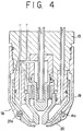
- Fig. 4 shows a further embodiment in which the nozzle protection cap is provided with a front end side portion and a base end side portion which are formed of different materials.
- the nozzle protection cap 5b has the base end portion 19 screwed with the nozzle body 13 and the front end portion 20 on the side of the nozzle 2, these portions 19 and 20 being formed by the different members, and the insulator 14a is supported on the side of this front end portion 20.
- the coupling of the base end portion 19 and the front end portion 20 will be performed by providing a flange portion 20a on the side of the front end portion and a flange portion, which is engaged with the flange portion 20a, formed to the base end portion 19.
- the flange portion of the base end portion 19 is fixedly fitted to this flange portion 20a or both end portions are fixedly screwed with each other by means of screw.
- the front end portion of the nozzle protection cap 5b is damaged, but according to this embodiment, only the front end portion 20 thereof can be exchanged, thus being economical in comparison with a full change of the nozzle protection cap.
- the nozzle protection cap 5b is provided with the divided base end portion 19 and front end portion 20, it is possible that both the portions can be formed with different materials, and by forming the front end portion 20 with a material having a good thermal conductive property, even if high temperature fused metal adheres, the fused metal can be cooled for a short time and then easily peeled off. Further, the torch cannot be deformed even in contact with the workpiece to be cut by forming the base end portion 19 with a material having good mechanical strength.
- Fig. 5 shows a further embodiment capable of cooling the nozzle protection cap.
- annular cooling water chamber 21 is formed inside a base end portion 19a of a nozzle protection cap 5c and the annular cooling water chamber 21 communicated with a cooling water chamber 9 inside the electrode 1 on the side of the electrode 1.
- the base end portion of the nozzle protection cap 5c is cooled by the cooling water in the cooling water chamber 21 to thereby suppress the temperature rising of the nozzle protection cap.
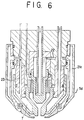
- Fig. 6 shows a further embodiment having a structure for cooling the nozzle protection cap, in which the cooling water chamber 21a of the nozzle protection cap 5d is formed to provide a vertically widened annular structure to thereby improve a cooling capacity to that portion.
- this cooling water chamber 21a other than the passage 22 on the flow-in side communicated with the cooling water chamber 9 on the side of the electrode 1, there is communicated a passage on a flow-out side communicated with the cooling water passage 7 provided around the nozzle 2.
- the secondary gas flow jetted from the gap of the nozzle protection cap can be made as a gyrating flow by forming spirally, with respect to the central portion of the torch, the rectifying passage formed to the insulator 14a.
- a plurality of plasma gas flow-in passages 6a for introducing the plasma gas into the plasma gas passage 6 provided around the electrode 1 are formed as shown in Fig. 8 with inclined state with respect to the axis of the torch so as to thereby impart the gyrating flow to the plasma gas flown into the plasma gas passage 6.
- the length L of the orifice of the nozzle 2 is determined to have relation of L/ ⁇ 1 ⁇ 2 with respect to the orifice diameter ⁇ 1.
- the gyrating direction of the secondary gas is made to accord with the gyrating direction of the plasma gas.
- the wall 24a to be cut on the upstream side of the gyrating flow of the secondary gas is made perpendicular and another wall 24b is cut with inclination so as to open at its front end side.
- the right side cut wall 24a is made perpendicular.
- a tube 26 formed of an electrically insulating material is fitted into the flow-in passage 25 communicating the cooling water chamber 9 on the side of the electrode 1 with the cooling water passage 10 on the side of the nozzle 2.
Landscapes
- Physics & Mathematics (AREA)
- Engineering & Computer Science (AREA)
- Plasma & Fusion (AREA)
- Spectroscopy & Molecular Physics (AREA)
- Geometry (AREA)
- Plasma Technology (AREA)
- Arc Welding In General (AREA)
Abstract
Applications Claiming Priority (5)
| Application Number | Priority Date | Filing Date | Title |
|---|---|---|---|
| JP17154/91U | 1991-02-28 | ||
| JP1715491 | 1991-02-28 | ||
| JP33399/91U | 1991-04-12 | ||
| JP3339991 | 1991-04-12 | ||
| PCT/JP1992/000239 WO1992015421A1 (fr) | 1991-02-28 | 1992-02-28 | Chalumeau coupeur a plasma |
Publications (3)
| Publication Number | Publication Date |
|---|---|
| EP0573653A1 true EP0573653A1 (fr) | 1993-12-15 |
| EP0573653A4 EP0573653A4 (fr) | 1994-03-17 |
| EP0573653B1 EP0573653B1 (fr) | 1998-01-21 |
Family
ID=26353640
Family Applications (1)
| Application Number | Title | Priority Date | Filing Date |
|---|---|---|---|
| EP92906228A Expired - Lifetime EP0573653B1 (fr) | 1991-02-28 | 1992-02-28 | Chalumeau coupeur a plasma |
Country Status (4)
| Country | Link |
|---|---|
| US (1) | US5393952A (fr) |
| EP (1) | EP0573653B1 (fr) |
| DE (1) | DE69224183T2 (fr) |
| WO (1) | WO1992015421A1 (fr) |
Cited By (7)
| Publication number | Priority date | Publication date | Assignee | Title |
|---|---|---|---|---|
| EP0710054A1 (fr) * | 1994-10-26 | 1996-05-01 | Matsushita Electric Industrial Co., Ltd. | Torche à plasma micro-ondes et procédé de formation du plasma |
| EP0872300A4 (fr) * | 1995-01-31 | 1998-10-21 | ||
| FR2779316A1 (fr) * | 1998-05-29 | 1999-12-03 | Aerospatiale | Dispositif de melange de gaz froid en sortie de torche a plasma |
| EP1061782A3 (fr) * | 1999-06-16 | 2004-01-07 | Gerrard Thomas Hughen | Tête de torche à plasma d'arc |
| WO2011018070A1 (fr) * | 2009-08-11 | 2011-02-17 | Kjellberg Finsterwalde Plasma Und Maschinen Gmbh | Capot de protection de buse et porte-capot de protection de buse ainsi que torche à plasma équipée de l'un et/ou de l'autre |
| CN104470187A (zh) * | 2014-11-13 | 2015-03-25 | 周开根 | 一种用于热解水的双级电弧等离子体喷枪 |
| US11178746B2 (en) | 2016-10-06 | 2021-11-16 | Kjellberg-Stiftung | Protective nozzle cap, plasma arc torch comprising said protective nozzle cap, and use of the plasma arc torch |
Families Citing this family (57)
| Publication number | Priority date | Publication date | Assignee | Title |
|---|---|---|---|---|
| US5695662A (en) * | 1988-06-07 | 1997-12-09 | Hypertherm, Inc. | Plasma arc cutting process and apparatus using an oxygen-rich gas shield |
| US5278388A (en) * | 1993-06-07 | 1994-01-11 | Huang Huang Nan | Plasma welding and cutting gun for discharging plasma gas with constant outlet pressure |
| US5518443A (en) * | 1994-05-13 | 1996-05-21 | Norton Company | Superabrasive tool |
| EP0747161A1 (fr) * | 1995-06-07 | 1996-12-11 | Daido Tokushuko Kabushiki Kaisha | Méthode et appareil de découpe plasma pour structures en béton |
| US5771818A (en) * | 1996-05-20 | 1998-06-30 | Prometron Technics Co., Ltd. | Cooling system for waste disposal device |
| US5760363A (en) * | 1996-09-03 | 1998-06-02 | Hypertherm, Inc. | Apparatus and method for starting and stopping a plasma arc torch used for mechanized cutting and marking applications |
| US5841095A (en) * | 1996-10-28 | 1998-11-24 | Hypertherm, Inc. | Apparatus and method for improved assembly concentricity in a plasma arc torch |
| US5856647A (en) * | 1997-03-14 | 1999-01-05 | The Lincoln Electric Company | Drag cup for plasma arc torch |
| DE19716235C2 (de) * | 1997-04-18 | 2001-11-29 | Deutsch Zentr Luft & Raumfahrt | Plasmabrenner mit einer fluidgekühlten Anode |
| US5906758A (en) * | 1997-09-30 | 1999-05-25 | The Esab Group, Inc. | Plasma arc torch |
| US6054669A (en) * | 1998-05-20 | 2000-04-25 | The Esab Group, Inc. | Plasma marking torch and method of operating same |
| US6677551B2 (en) | 1998-10-23 | 2004-01-13 | Innerlogic, Inc. | Process for operating a plasma arc torch |
| US6326583B1 (en) | 2000-03-31 | 2001-12-04 | Innerlogic, Inc. | Gas control system for a plasma arc torch |
| US6498317B2 (en) | 1998-10-23 | 2002-12-24 | Innerlogic, Inc. | Process for operating a plasma arc torch |
| US6163009A (en) * | 1998-10-23 | 2000-12-19 | Innerlogic, Inc. | Process for operating a plasma arc torch |
| US6156995A (en) * | 1998-12-02 | 2000-12-05 | The Esab Group, Inc. | Water-injection nozzle assembly with insulated front end |
| US6096992A (en) * | 1999-01-29 | 2000-08-01 | The Esab Group, Inc. | Low current water injection nozzle and associated method |
| JP2000317639A (ja) * | 1999-05-12 | 2000-11-21 | Komatsu Ltd | プラズマ切断方法及び装置 |
| US6337460B2 (en) | 2000-02-08 | 2002-01-08 | Thermal Dynamics Corporation | Plasma arc torch and method for cutting a workpiece |
| RU2192338C2 (ru) * | 2000-08-10 | 2002-11-10 | Акционерное общество открытого типа "Научно-исследовательский технологический институт" | Плазмотрон для воздушно-плазменной резки |
| US6667459B1 (en) | 2000-11-21 | 2003-12-23 | Hypertherm, Inc. | Configurable nozzle baffle apparatus and method |
| US6703581B2 (en) | 2001-02-27 | 2004-03-09 | Thermal Dynamics Corporation | Contact start plasma torch |
| RU2212773C2 (ru) * | 2001-11-16 | 2003-09-20 | Авдеев Аркадий Игоревич | Дуговой плазмотрон авдеевых |
| CZ301297B6 (cs) * | 2002-04-19 | 2010-01-06 | Thermal Dynamics Corporation | Plazmový obloukový horák, elektroda tohoto horáku a zpusob provozování tohoto horáku |
| ITBO20030016A1 (it) * | 2003-01-14 | 2004-07-15 | Cebora Spa | Torcia al plasma ad accensione per contatto. |
| DE202004021663U1 (de) | 2004-10-08 | 2010-05-12 | Kjellberg Finsterwalde Plasma Und Maschinen Gmbh | Plasmabrenner |
| US10098217B2 (en) | 2012-07-19 | 2018-10-09 | Hypertherm, Inc. | Composite consumables for a plasma arc torch |
| US9560732B2 (en) | 2006-09-13 | 2017-01-31 | Hypertherm, Inc. | High access consumables for a plasma arc cutting system |
| US10194516B2 (en) | 2006-09-13 | 2019-01-29 | Hypertherm, Inc. | High access consumables for a plasma arc cutting system |
| US9662747B2 (en) | 2006-09-13 | 2017-05-30 | Hypertherm, Inc. | Composite consumables for a plasma arc torch |
| EP2022299B1 (fr) * | 2007-02-16 | 2014-04-30 | Hypertherm, Inc | Torche de découpe à plasma d'arc refroidie au gaz |
| CN101483968B (zh) * | 2008-01-08 | 2012-01-11 | 财团法人工业技术研究院 | 喷射式等离子枪与应用其的等离子处理设备 |
| US8389887B2 (en) | 2008-03-12 | 2013-03-05 | Hypertherm, Inc. | Apparatus and method for a liquid cooled shield for improved piercing performance |
| US8212173B2 (en) * | 2008-03-12 | 2012-07-03 | Hypertherm, Inc. | Liquid cooled shield for improved piercing performance |
| US20100276397A1 (en) * | 2009-05-01 | 2010-11-04 | Baker Hughes Incorporated | Electrically isolated gas cups for plasma transfer arc welding torches, and related methods |
| US8853589B2 (en) | 2009-07-03 | 2014-10-07 | Kjellberg Finsterwalde Plasma Und Maschinen Gmbh | Nozzle for a liquid-cooled plasma torch and plasma torch head having the same |
| DE102009031857C5 (de) * | 2009-07-03 | 2017-05-11 | Kjellberg Finsterwalde Plasma Und Maschinen Gmbh | Düse für einen flüssigkeitsgekühlten Plasmabrenner sowie Plasmabrennerkopf mit derselben |
| US11783138B2 (en) | 2012-04-04 | 2023-10-10 | Hypertherm, Inc. | Configuring signal devices in thermal processing systems |
| US9949356B2 (en) | 2012-07-11 | 2018-04-17 | Lincoln Global, Inc. | Electrode for a plasma arc cutting torch |
| ES2923761T3 (es) * | 2013-05-16 | 2022-09-30 | Kjellberg Stiftung | Pieza aislante de varias partes para un soplete de arco de plasma, soplete y conjuntos asociados que utilizan la misma y procedimientos asociados |
| US10716199B2 (en) * | 2013-07-25 | 2020-07-14 | Hypertherm, Inc. | Devices for gas cooling plasma arc torches and related systems and methods |
| US12521905B2 (en) | 2014-03-07 | 2026-01-13 | Hypertherm, Inc. | Liquid pressurization pump and systems with data storage |
| EP2942144B1 (fr) * | 2014-05-07 | 2024-07-03 | Kjellberg-Stiftung | Système de brûleur pour découpage au jet plasma et utilisation de pièces d'usure pour un système de brûleur pour découpage au jet de plasma |
| DE202015002334U1 (de) * | 2014-10-14 | 2015-06-17 | Hypertherm, Inc. | Verbrauchsteile mit hoher Zugänglichkeit für ein Plasmalichtbogenschneidsystem |
| WO2016060840A1 (fr) * | 2014-10-14 | 2016-04-21 | Hypertherm, Inc. | Consommables à grand accès pour système de coupage à l'arc plasma |
| EP3307030B1 (fr) * | 2015-06-02 | 2020-04-29 | FUJI Corporation | Dispositif générateur de plasma |
| AU2016301372B2 (en) | 2015-08-04 | 2021-07-29 | Hypertherm, Inc. | Cartridge for a liquid-cooled plasma ARC torch |
| CN107249803B (zh) * | 2015-08-04 | 2020-01-31 | 海别得公司 | 改进的等离子弧切割系统、消耗品和操作方法 |
| CN107454730B (zh) * | 2016-04-11 | 2020-03-03 | 海别得公司 | 包括回旋环的等离子体电弧切割系统和有关运行方法 |
| EP3527049B1 (fr) * | 2016-10-12 | 2023-05-24 | The ESAB Group Inc. | Ensemble consommable ayant des éléments internes d'élimination de chaleur et procédé de refroidissement associé |
| KR102518327B1 (ko) | 2017-02-09 | 2023-04-04 | 하이퍼썸, 인크. | 플라즈마 아크 토치 카트리지를 위한 선회 링 및 콘택 요소 |
| CN108127236B (zh) * | 2018-02-05 | 2024-06-21 | 常州九圣焊割设备股份有限公司 | 高效散热式等离子弧割炬 |
| CN110315177B (zh) * | 2019-08-06 | 2024-09-13 | 河北瓦尔丁科技有限公司 | 等离子电源割炬头加速气路装置 |
| CN111590175A (zh) * | 2020-06-01 | 2020-08-28 | 中国石油大学(华东) | 一种石油套管切割等离子喷头 |
| US12103105B2 (en) * | 2021-01-28 | 2024-10-01 | Ii-Vi Delaware, Inc. | Nozzle adapter for laser cutting head |
| CN114453715A (zh) * | 2021-09-06 | 2022-05-10 | 中海油能源发展股份有限公司 | 一种海洋石油套管等离子熔融开窗工具头及其使用方法 |
| CN119407295A (zh) * | 2025-01-07 | 2025-02-11 | 山东伊诺维森焊割科技有限公司 | 一种可改变电弧形态的多气体等离子电弧气刨刨炬 |
Family Cites Families (12)
| Publication number | Priority date | Publication date | Assignee | Title |
|---|---|---|---|---|
| US3204076A (en) * | 1962-10-04 | 1965-08-31 | Thermal Dynamics Corp | Electric arc torch |
| CH593754A5 (fr) * | 1976-01-15 | 1977-12-15 | Castolin Sa | |
| JPS54105342A (en) * | 1978-02-07 | 1979-08-18 | Mitsubishi Electric Corp | Glow-discharge heating device |
| JPS53119753A (en) * | 1977-03-30 | 1978-10-19 | Hitachi Seiko Kk | Arc torch |
| US4389559A (en) * | 1981-01-28 | 1983-06-21 | Eutectic Corporation | Plasma-transferred-arc torch construction |
| JPS57165370A (en) * | 1981-03-18 | 1982-10-12 | Ici Ltd | Triazole or imidazole compounds, manufacture and fungicidal or plant growth regulant agent |
| JPS57165370U (fr) * | 1981-04-09 | 1982-10-18 | ||
| US4521666A (en) * | 1982-12-23 | 1985-06-04 | Union Carbide Corporation | Plasma arc torch |
| JPS63154272A (ja) * | 1986-12-17 | 1988-06-27 | Mitsubishi Heavy Ind Ltd | プラズマト−チ |
| US4861962B1 (en) * | 1988-06-07 | 1996-07-16 | Hypertherm Inc | Nozzle shield for a plasma arc torch |
| JPH0220667A (ja) * | 1988-07-06 | 1990-01-24 | Origin Electric Co Ltd | プラズマトーチ |
| US4954688A (en) * | 1989-11-01 | 1990-09-04 | Esab Welding Products, Inc. | Plasma arc cutting torch having extended lower nozzle member |
-
1992
- 1992-02-28 EP EP92906228A patent/EP0573653B1/fr not_active Expired - Lifetime
- 1992-02-28 WO PCT/JP1992/000239 patent/WO1992015421A1/fr not_active Ceased
- 1992-02-28 DE DE69224183T patent/DE69224183T2/de not_active Expired - Fee Related
- 1992-02-28 US US08/107,815 patent/US5393952A/en not_active Expired - Lifetime
Cited By (14)
| Publication number | Priority date | Publication date | Assignee | Title |
|---|---|---|---|---|
| EP0710054A1 (fr) * | 1994-10-26 | 1996-05-01 | Matsushita Electric Industrial Co., Ltd. | Torche à plasma micro-ondes et procédé de formation du plasma |
| US5734143A (en) * | 1994-10-26 | 1998-03-31 | Matsushita Electric Industrial Co., Ltd. | Microwave plasma torch having discretely positioned gas injection holes and method for generating plasma |
| EP0872300A4 (fr) * | 1995-01-31 | 1998-10-21 | ||
| US5874707A (en) * | 1995-01-31 | 1999-02-23 | Komatsu Ltd. | Processing torch having a separably assembled torch base and torch head |
| FR2779316A1 (fr) * | 1998-05-29 | 1999-12-03 | Aerospatiale | Dispositif de melange de gaz froid en sortie de torche a plasma |
| EP1061782A3 (fr) * | 1999-06-16 | 2004-01-07 | Gerrard Thomas Hughen | Tête de torche à plasma d'arc |
| WO2011018070A1 (fr) * | 2009-08-11 | 2011-02-17 | Kjellberg Finsterwalde Plasma Und Maschinen Gmbh | Capot de protection de buse et porte-capot de protection de buse ainsi que torche à plasma équipée de l'un et/ou de l'autre |
| CN102474970A (zh) * | 2009-08-11 | 2012-05-23 | 谢尔贝格芬斯特瓦德电子及机械有限公司 | 喷嘴保护罩和喷嘴保护罩保持架以及具有喷嘴保护罩和/或喷嘴保护罩保持架的电弧等离子燃烧器 |
| US8921731B2 (en) | 2009-08-11 | 2014-12-30 | Kjellberg Finsterwalde Plasma Und Maschinen Gmbh | Protective nozzle cap, protective nozzle cap retainer, and arc plasma torch having said protective nozzle cap and or said protective nozzle cap retainer |
| CN102474970B (zh) * | 2009-08-11 | 2015-05-27 | 谢尔贝格芬斯特瓦德电子及机械有限公司 | 喷嘴保护罩和喷嘴保护罩保持架以及具有喷嘴保护罩和/或喷嘴保护罩保持架的电弧等离子燃烧器 |
| CN104470187A (zh) * | 2014-11-13 | 2015-03-25 | 周开根 | 一种用于热解水的双级电弧等离子体喷枪 |
| CN104470187B (zh) * | 2014-11-13 | 2016-10-05 | 衢州昀睿工业设计有限公司 | 一种用于热解水的双级电弧等离子体喷枪 |
| US11178746B2 (en) | 2016-10-06 | 2021-11-16 | Kjellberg-Stiftung | Protective nozzle cap, plasma arc torch comprising said protective nozzle cap, and use of the plasma arc torch |
| EP3524038B1 (fr) * | 2016-10-06 | 2023-06-07 | Kjellberg-Stiftung | Capot de protection de buse, torche à plasma équipée de l'un ainsi qu'utilisation de la torche à plasma |
Also Published As
| Publication number | Publication date |
|---|---|
| US5393952A (en) | 1995-02-28 |
| WO1992015421A1 (fr) | 1992-09-17 |
| EP0573653A4 (fr) | 1994-03-17 |
| EP0573653B1 (fr) | 1998-01-21 |
| DE69224183D1 (de) | 1998-02-26 |
| DE69224183T2 (de) | 1998-06-18 |
Similar Documents
| Publication | Publication Date | Title |
|---|---|---|
| US5393952A (en) | Plasma torch for cutting use with nozzle protection cap having annular secondary GPS passage and insulator disposed in the secondary gas passage | |
| US5756959A (en) | Coolant tube for use in a liquid-cooled electrode disposed in a plasma arc torch | |
| JP3157164B2 (ja) | プラズマアークトーチのための改良ノズル及び改良運転方法 | |
| US4777343A (en) | Plasma arc apparatus | |
| JP2640707B2 (ja) | 切断用プラズマトーチ | |
| CA1234689A (fr) | Pistolet au plasma | |
| JP3172532B2 (ja) | プラズマアーク切断方法及び装置 | |
| US6946617B2 (en) | Method and apparatus for alignment of components of a plasma arc torch | |
| US4055741A (en) | Plasma arc torch | |
| KR101696872B1 (ko) | 플라즈마 용사 시스템의 플라즈마건 장치 및 이를 구비한 플라즈마 용사 시스템 | |
| EP0339563B1 (fr) | Torche à plasma à arc transféré | |
| US20080116179A1 (en) | Method and apparatus for alignment of components of a plasma arc torch | |
| US3858072A (en) | Plasma torch with axial supply of the stabilizing gas | |
| CN101541465A (zh) | 具有优化水冷却的等离子弧切割焊炬部件 | |
| WO1993023193A1 (fr) | Electrode amelioree pour un chalumeau a arc de plasma a haute densite de courant | |
| KR100272917B1 (ko) | 플라즈마 절단 방법 | |
| EP0072409B1 (fr) | Buse pour un pistolet à plasma | |
| JP2689310B2 (ja) | 切断用プラズマトーチ及びプラズマ切断方法 | |
| JP2997224B2 (ja) | プラズマ切断機 | |
| CN223185722U (zh) | 用于激光加工装置的节流喷嘴及激光加工头 | |
| WO1993016835A1 (fr) | Torche a plasma destinee au decoupage | |
| JP2689310C (fr) | ||
| CN209953979U (zh) | 用于等离子弧割炬的外固定罩 | |
| KR970004755Y1 (ko) | 플라즈마 아아크 토오치의 냉각구조 | |
| KR100232280B1 (ko) | 플라즈마 아크 토치 |
Legal Events
| Date | Code | Title | Description |
|---|---|---|---|
| PUAI | Public reference made under article 153(3) epc to a published international application that has entered the european phase |
Free format text: ORIGINAL CODE: 0009012 |
|
| 17P | Request for examination filed |
Effective date: 19930826 |
|
| AK | Designated contracting states |
Kind code of ref document: A1 Designated state(s): DE GB IT |
|
| 17Q | First examination report despatched |
Effective date: 19950510 |
|
| GRAG | Despatch of communication of intention to grant |
Free format text: ORIGINAL CODE: EPIDOS AGRA |
|
| GRAG | Despatch of communication of intention to grant |
Free format text: ORIGINAL CODE: EPIDOS AGRA |
|
| GRAH | Despatch of communication of intention to grant a patent |
Free format text: ORIGINAL CODE: EPIDOS IGRA |
|
| GRAH | Despatch of communication of intention to grant a patent |
Free format text: ORIGINAL CODE: EPIDOS IGRA |
|
| GRAA | (expected) grant |
Free format text: ORIGINAL CODE: 0009210 |
|
| AK | Designated contracting states |
Kind code of ref document: B1 Designated state(s): DE GB IT |
|
| ITF | It: translation for a ep patent filed | ||
| PGFP | Annual fee paid to national office [announced via postgrant information from national office to epo] |
Ref country code: GB Payment date: 19980219 Year of fee payment: 7 |
|
| REF | Corresponds to: |
Ref document number: 69224183 Country of ref document: DE Date of ref document: 19980226 |
|
| PLBE | No opposition filed within time limit |
Free format text: ORIGINAL CODE: 0009261 |
|
| STAA | Information on the status of an ep patent application or granted ep patent |
Free format text: STATUS: NO OPPOSITION FILED WITHIN TIME LIMIT |
|
| 26N | No opposition filed | ||
| PG25 | Lapsed in a contracting state [announced via postgrant information from national office to epo] |
Ref country code: GB Free format text: LAPSE BECAUSE OF NON-PAYMENT OF DUE FEES Effective date: 19990228 |
|
| GBPC | Gb: european patent ceased through non-payment of renewal fee |
Effective date: 19990228 |
|
| PGFP | Annual fee paid to national office [announced via postgrant information from national office to epo] |
Ref country code: DE Payment date: 20030313 Year of fee payment: 12 |
|
| PG25 | Lapsed in a contracting state [announced via postgrant information from national office to epo] |
Ref country code: DE Free format text: LAPSE BECAUSE OF NON-PAYMENT OF DUE FEES Effective date: 20040901 |
|
| PG25 | Lapsed in a contracting state [announced via postgrant information from national office to epo] |
Ref country code: IT Free format text: LAPSE BECAUSE OF NON-PAYMENT OF DUE FEES;WARNING: LAPSES OF ITALIAN PATENTS WITH EFFECTIVE DATE BEFORE 2007 MAY HAVE OCCURRED AT ANY TIME BEFORE 2007. THE CORRECT EFFECTIVE DATE MAY BE DIFFERENT FROM THE ONE RECORDED. Effective date: 20050228 |