EP0573678A1 - Tour multibroche - Google Patents
Tour multibroche Download PDFInfo
- Publication number
- EP0573678A1 EP0573678A1 EP92109141A EP92109141A EP0573678A1 EP 0573678 A1 EP0573678 A1 EP 0573678A1 EP 92109141 A EP92109141 A EP 92109141A EP 92109141 A EP92109141 A EP 92109141A EP 0573678 A1 EP0573678 A1 EP 0573678A1
- Authority
- EP
- European Patent Office
- Prior art keywords
- spindle
- tool
- workpiece
- machining
- assigned
- Prior art date
- Legal status (The legal status is an assumption and is not a legal conclusion. Google has not performed a legal analysis and makes no representation as to the accuracy of the status listed.)
- Granted
Links
- 238000003754 machining Methods 0.000 claims abstract description 41
- 239000000969 carrier Substances 0.000 claims abstract description 18
- 150000001875 compounds Chemical class 0.000 abstract 1
- 238000000034 method Methods 0.000 description 1
Images


Classifications
-
- B—PERFORMING OPERATIONS; TRANSPORTING
- B23—MACHINE TOOLS; METAL-WORKING NOT OTHERWISE PROVIDED FOR
- B23B—TURNING; BORING
- B23B3/00—General-purpose turning-machines or devices, e.g. centre lathes with feed rod and lead screw; Sets of turning-machines
- B23B3/30—Turning-machines with two or more working-spindles, e.g. in fixed arrangement
-
- B—PERFORMING OPERATIONS; TRANSPORTING
- B23—MACHINE TOOLS; METAL-WORKING NOT OTHERWISE PROVIDED FOR
- B23Q—DETAILS, COMPONENTS, OR ACCESSORIES FOR MACHINE TOOLS, e.g. ARRANGEMENTS FOR COPYING OR CONTROLLING; MACHINE TOOLS IN GENERAL CHARACTERISED BY THE CONSTRUCTION OF PARTICULAR DETAILS OR COMPONENTS; COMBINATIONS OR ASSOCIATIONS OF METAL-WORKING MACHINES, NOT DIRECTED TO A PARTICULAR RESULT
- B23Q39/00—Metal-working machines incorporating a plurality of sub-assemblies, each capable of performing a metal-working operation
- B23Q39/04—Metal-working machines incorporating a plurality of sub-assemblies, each capable of performing a metal-working operation the sub-assemblies being arranged to operate simultaneously at different stations, e.g. with an annular work-table moved in steps
- B23Q39/042—Metal-working machines incorporating a plurality of sub-assemblies, each capable of performing a metal-working operation the sub-assemblies being arranged to operate simultaneously at different stations, e.g. with an annular work-table moved in steps with circular arrangement of the sub-assemblies
- B23Q39/044—Metal-working machines incorporating a plurality of sub-assemblies, each capable of performing a metal-working operation the sub-assemblies being arranged to operate simultaneously at different stations, e.g. with an annular work-table moved in steps with circular arrangement of the sub-assemblies having at least one tool station cooperating with each work holder, e.g. multi-spindle lathes
-
- B—PERFORMING OPERATIONS; TRANSPORTING
- B23—MACHINE TOOLS; METAL-WORKING NOT OTHERWISE PROVIDED FOR
- B23Q—DETAILS, COMPONENTS, OR ACCESSORIES FOR MACHINE TOOLS, e.g. ARRANGEMENTS FOR COPYING OR CONTROLLING; MACHINE TOOLS IN GENERAL CHARACTERISED BY THE CONSTRUCTION OF PARTICULAR DETAILS OR COMPONENTS; COMBINATIONS OR ASSOCIATIONS OF METAL-WORKING MACHINES, NOT DIRECTED TO A PARTICULAR RESULT
- B23Q39/00—Metal-working machines incorporating a plurality of sub-assemblies, each capable of performing a metal-working operation
- B23Q39/04—Metal-working machines incorporating a plurality of sub-assemblies, each capable of performing a metal-working operation the sub-assemblies being arranged to operate simultaneously at different stations, e.g. with an annular work-table moved in steps
- B23Q39/048—Metal-working machines incorporating a plurality of sub-assemblies, each capable of performing a metal-working operation the sub-assemblies being arranged to operate simultaneously at different stations, e.g. with an annular work-table moved in steps the work holder of a work station transfers directly its workpiece to the work holder of a following work station
Definitions
- the invention relates to a multi-spindle lathe with three workpiece spindles, which are mounted in a spindle drum that can be pivoted about a horizontal axis and switchable in three spindle positions, and have clamping devices for the workpieces to be machined, each spindle position being associated with tool carriers with tools that can be moved relative to the workpieces and that the tool carriers assigned to the first and second spindle positions are turret heads arranged on cross slides.
- a known lathe of this type (DE-A-17 52 738) two spindle positions are each assigned cross slides with tool turrets, while the third spindle position corresponds to a tool carrier that can only be moved in the direction of the spindle axis and has driven machining tools.
- the tool turrets assigned to the first two spindle positions carry both the internal and external machining tools. Processing with these tools can therefore only take place one after the other.
- the third spindle position of the known lathe is turned, it is used for loading and unloading as well as for additional internal machining with driven tools. Since only two spindle positions are available for the external machining of the workpieces, a division of the machining processes between the various spindle positions or workpiece spindles, which is aimed for as economically as possible, is excluded.
- a multi-spindle lathe with three tool spindles is also known (DE-A-16 52 670), in which a spindle position is blocked only for the loading and unloading process.
- a cross slide with tools for external machining is assigned to a second spindle position and a switchable drill head carrier for driven internal machining tools is provided in the third spindle position.
- the drill heads take over the feed movement in the direction of the spindle axis.
- the inner machining and the outer machining are strictly separated from one another on two different spindle positions. Since the duration of the external machining generally differs greatly from the machining duration of the internal machining, good utilization of the known machine tool is therefore impossible. This disadvantage is exacerbated by the reservation of the third spindle position exclusively for loading and unloading.
- a multi-spindle machine with significantly more than three spindles is known (EP-A-298 672), in which a plurality of workpiece spindles is assigned an external machining tool on a cross slide and an internal machining tool on a central tool block.
- a counter spindle is provided on a cross slide, which can grip the workpiece machined on one side from the opposing main spindle and feed it to further machining by a tool turret.
- the tool turret is exclusively assigned to the counter spindle, while the main spindles are not assigned any switchable tool carriers.
- the cycle frequency of the drum circuit in multi-spindle lathes is determined by the longest machining time on one spindle position.
- the machining times must therefore be distributed as evenly as possible over the workpiece spindles in order to achieve the best possible utilization.
- the invention is therefore based on the object of creating a multi-spindle lathe with only three workpiece spindles in a spindle drum, which is particularly well suited for flexible use with as uniform a distribution of the machining times as possible over the different spindle positions, these spindle positions temporally corresponding to the loading and unloading operations and the rear processing operations should be harmonized.
- first and second spindle positions are additionally assigned tool carriers which can be displaced in the spindle axis direction and the third spindle position is coaxially opposite a counter spindle which can be moved in the spindle axis direction and which takes over the workpiece from the respective one opposite main spindle and for holding the workpiece during a rear turning machining is formed
- the tool carrier assigned to the third spindle position carries a plurality of non-driven tools, at least one of which is designed and arranged for machining on the main spindle and at least one for machining on the counter spindle.
- first and second spindle positions are each assigned two tool carriers, one of which can be moved in the x direction and z direction and the other of which can be moved at least in the z direction, any operations can be distributed over the first two spindle positions.
- Such a distribution over the spindle positions 1 and 2 is necessary since the machining on these first two spindle positions must take at least the time longer than the time required for the workpiece feed and workpiece removal in the third spindle position. Since the workpiece feed and workpiece removal or workpiece transfer always takes place in the third spindle position, it is sufficient to provide only a single tool carrier in the third spindle position, with which time-limited machining on the main spindle and residual machining on the opposite counter spindle can take place.
- This tool holder which is assigned both to the third spindle position and to the opposing counter spindle, therefore serves, because of the oppositely directed tools, for machining workpieces clamped on both opposing spindles.
- the multi-spindle lathe according to the invention allows evenly distributed and collision-free machining two tools in the first two spindle positions if external machining tools are preferably arranged on the tool carriers assigned to these spindle positions and internal machining tools are preferably arranged on the additional tool carriers.
- the adjustment of the additional tool carriers serves both to compensate for cutting edge wear and to compensate for deviations in the tool diameter from the machining diameter and the tool change.
- a multi-spindle automatic lathe equipped in this way can be used for both chuck processing and bar processing.
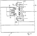
- the machine frame 1 has a spindle drum stand 1a, in which a spindle drum 2 can be switched about a horizontal axis in three pivot positions offset from one another by 120 °.
- a spindle drum 2 In the spindle drum 2, three workpiece spindles 3, 4 and 5 are each offset by 120 ° to one another, which have clamping devices for the workpieces 13, 14 and 15 to be machined.
- the position of the workpiece spindle 3 in Figure 2 is the first spindle position 3 '
- the position of the workpiece spindle 4 in Figure 2 is the second spindle position 4'
- the position of the workpiece spindle 5 in Figure 2 is the third spindle position 5 '.
- a cross slide 8 which has a turret 8a as a tool carrier, interacts with the first spindle position 3 'according to the spindle 3.
- the cross slide 8 can be moved in the x direction and z direction.
- the first and second spindle positions are assigned additional tool slides 9 and 10 which can be displaced in the direction of the spindle axis.
- the third spindle position 5 'according to the workpiece spindle 5 is opposed by a counter spindle 16 with a fixed axis of rotation, which can be moved in the z-axis direction.
- the counter spindle 16 can remove the workpiece 15 from the opposite workpiece spindle 5, so that this workpiece can be machined on the rear side.
- a cross slide 7 which can be moved in the x and z directions and which has a turret head 7a as a tool carrier works together with the workpiece spindle 5 and the counter spindle 16.
- a tool 7c is directed towards the counter spindle 16, a tool 7b is used to machine the workpiece 15 in the workpiece spindle 5.
- Cross slides 9a and 10a according to FIG. 2 can be attached to the additional tool slides 9 and 10, which enable the exchange of several internal machining tools.
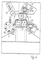
- FIG. 3 shows the multi-spindle lathe with a view of the workpiece spindles 3 and 4, to which the additional longitudinal slides 9 and 10 with crown turrets 9b and 10b for the internal machining tools are assigned.
- additional tool slides 9 and 10 are designed as cross slides, external machining tools can alternatively be arranged thereon.
Landscapes
- Engineering & Computer Science (AREA)
- Mechanical Engineering (AREA)
- Turning (AREA)
Priority Applications (2)
| Application Number | Priority Date | Filing Date | Title |
|---|---|---|---|
| EP19920109141 EP0573678B1 (fr) | 1992-05-29 | 1992-05-29 | Tour multibroche |
| DE59201551T DE59201551D1 (de) | 1992-05-29 | 1992-05-29 | Mehrspindel-Drehmaschine. |
Applications Claiming Priority (1)
| Application Number | Priority Date | Filing Date | Title |
|---|---|---|---|
| EP19920109141 EP0573678B1 (fr) | 1992-05-29 | 1992-05-29 | Tour multibroche |
Publications (2)
| Publication Number | Publication Date |
|---|---|
| EP0573678A1 true EP0573678A1 (fr) | 1993-12-15 |
| EP0573678B1 EP0573678B1 (fr) | 1995-03-01 |
Family
ID=8209662
Family Applications (1)
| Application Number | Title | Priority Date | Filing Date |
|---|---|---|---|
| EP19920109141 Expired - Lifetime EP0573678B1 (fr) | 1992-05-29 | 1992-05-29 | Tour multibroche |
Country Status (2)
| Country | Link |
|---|---|
| EP (1) | EP0573678B1 (fr) |
| DE (1) | DE59201551D1 (fr) |
Cited By (12)
| Publication number | Priority date | Publication date | Assignee | Title |
|---|---|---|---|---|
| EP0681881A1 (fr) * | 1994-05-13 | 1995-11-15 | TECNOMECCANICA G.R.W. S.r.l. | Machines de transfert multibroches pour cycles d'usinage |
| EP0800893A3 (fr) * | 1996-04-10 | 1998-01-28 | Chiron-Werke GmbH & Co. KG | Machine-outil avec une espace de travail |
| WO2002102545A1 (fr) * | 2001-06-19 | 2002-12-27 | Ex-Cell-O Gmbh | Machine-outil a plusieurs broches porte-pieces |
| WO2003084711A3 (fr) * | 2002-03-18 | 2004-03-04 | Miyano Machinery Japan Inc | Ensemble machine-outil |
| CH694269A5 (de) * | 1999-12-21 | 2004-10-29 | K R Pfiffner Ag | Mehrspindel-Werkzeugmaschine. |
| EP1632309A1 (fr) * | 2004-09-06 | 2006-03-08 | Tornos SA | Dispositif d'usinage en contre-opération dans un tour multibroches |
| EP1721701A1 (fr) * | 2005-05-10 | 2006-11-15 | Kummer Frères SA, Fabrique de machines | Procédé et machine-outil d'usinage avec un plateau tournant portant plusieurs pièces et un autre portant plusieurs outils |
| US20130104705A1 (en) * | 2010-04-09 | 2013-05-02 | Danieli & C. Officine Meccaniche Spa | Machine and method for the threading of sleeves |
| WO2015128210A1 (fr) * | 2014-02-25 | 2015-09-03 | Erwin Junker Maschinenfabrik Gmbh | Meuleuse et procédé de meulage de pièces comportant des alésages axiaux et des surfaces extérieures planes à usiner des deux côtés |
| CN108817423A (zh) * | 2018-07-26 | 2018-11-16 | 长沙航空职业技术学院 | 一种六轴车床 |
| WO2020075490A1 (fr) * | 2018-10-10 | 2020-04-16 | シチズン時計株式会社 | Machine-outil |
| WO2021047913A1 (fr) * | 2019-09-12 | 2021-03-18 | Index-Werke Gmbh & Co. Kg Hahn & Tessky | Machine-outil |
Citations (2)
| Publication number | Priority date | Publication date | Assignee | Title |
|---|---|---|---|---|
| DE1752738A1 (de) * | 1968-07-09 | 1971-07-01 | K Martin Fa | Werkzeugautomat |
| EP0356389A1 (fr) * | 1988-08-16 | 1990-02-28 | Tornos-Bechler SA Fabrique de Machines Moutier | Dispositif d'entraînement destiné à une machine d'usinage multibroches |
-
1992
- 1992-05-29 DE DE59201551T patent/DE59201551D1/de not_active Expired - Fee Related
- 1992-05-29 EP EP19920109141 patent/EP0573678B1/fr not_active Expired - Lifetime
Patent Citations (2)
| Publication number | Priority date | Publication date | Assignee | Title |
|---|---|---|---|---|
| DE1752738A1 (de) * | 1968-07-09 | 1971-07-01 | K Martin Fa | Werkzeugautomat |
| EP0356389A1 (fr) * | 1988-08-16 | 1990-02-28 | Tornos-Bechler SA Fabrique de Machines Moutier | Dispositif d'entraînement destiné à une machine d'usinage multibroches |
Cited By (20)
| Publication number | Priority date | Publication date | Assignee | Title |
|---|---|---|---|---|
| EP0681881A1 (fr) * | 1994-05-13 | 1995-11-15 | TECNOMECCANICA G.R.W. S.r.l. | Machines de transfert multibroches pour cycles d'usinage |
| EP0800893A3 (fr) * | 1996-04-10 | 1998-01-28 | Chiron-Werke GmbH & Co. KG | Machine-outil avec une espace de travail |
| US5927930A (en) * | 1996-04-10 | 1999-07-27 | Chiron Werke Gmbh | Machine tool having a working space |
| CH694269A5 (de) * | 1999-12-21 | 2004-10-29 | K R Pfiffner Ag | Mehrspindel-Werkzeugmaschine. |
| WO2002102545A1 (fr) * | 2001-06-19 | 2002-12-27 | Ex-Cell-O Gmbh | Machine-outil a plusieurs broches porte-pieces |
| WO2003084711A3 (fr) * | 2002-03-18 | 2004-03-04 | Miyano Machinery Japan Inc | Ensemble machine-outil |
| US7032484B2 (en) | 2002-03-18 | 2006-04-25 | Miyano Machinery Japan, Inc. | Machine tool assembly |
| EP1632309A1 (fr) * | 2004-09-06 | 2006-03-08 | Tornos SA | Dispositif d'usinage en contre-opération dans un tour multibroches |
| EP1721701A1 (fr) * | 2005-05-10 | 2006-11-15 | Kummer Frères SA, Fabrique de machines | Procédé et machine-outil d'usinage avec un plateau tournant portant plusieurs pièces et un autre portant plusieurs outils |
| US20130104705A1 (en) * | 2010-04-09 | 2013-05-02 | Danieli & C. Officine Meccaniche Spa | Machine and method for the threading of sleeves |
| WO2015128210A1 (fr) * | 2014-02-25 | 2015-09-03 | Erwin Junker Maschinenfabrik Gmbh | Meuleuse et procédé de meulage de pièces comportant des alésages axiaux et des surfaces extérieures planes à usiner des deux côtés |
| CN106061676A (zh) * | 2014-02-25 | 2016-10-26 | 埃尔温容克尔机械制造有限公司 | 磨削机以及用于磨削具有轴向孔以及具有在两侧需要加工的平坦的外部面的工件的方法 |
| US20170252886A1 (en) * | 2014-02-25 | 2017-09-07 | Erwin Junker Maschinenfabrik Gmbh | Grinding machine and method for grinding workpieces that have axial bores and planar external surfaces to be machined on both sides |
| US10058968B2 (en) * | 2014-02-25 | 2018-08-28 | Erwin Junker Maschinenfabrik Gmbh | Grinding machine and method for grinding workpieces that have axial bores and planar external surfaces to be machined on both sides |
| CN106061676B (zh) * | 2014-02-25 | 2019-03-15 | 埃尔温容克尔机械制造有限公司 | 磨削机以及用于磨削具有轴向孔以及具有在两侧需要加工的平坦的外部面的工件的方法 |
| CN108817423A (zh) * | 2018-07-26 | 2018-11-16 | 长沙航空职业技术学院 | 一种六轴车床 |
| CN108817423B (zh) * | 2018-07-26 | 2023-06-09 | 长沙航空职业技术学院 | 一种六轴车床 |
| WO2020075490A1 (fr) * | 2018-10-10 | 2020-04-16 | シチズン時計株式会社 | Machine-outil |
| US11919093B2 (en) | 2018-10-10 | 2024-03-05 | Citizen Watch Co., Ltd. | Machine tool |
| WO2021047913A1 (fr) * | 2019-09-12 | 2021-03-18 | Index-Werke Gmbh & Co. Kg Hahn & Tessky | Machine-outil |
Also Published As
| Publication number | Publication date |
|---|---|
| DE59201551D1 (de) | 1995-04-06 |
| EP0573678B1 (fr) | 1995-03-01 |
Similar Documents
| Publication | Publication Date | Title |
|---|---|---|
| EP0144306B1 (fr) | Tour | |
| EP1418019B2 (fr) | Machine-outil avec au moins deux tourettes revolver à outils, comprenant chacune un dispositif porte-pièce | |
| DE3420531C2 (de) | Drehautomat | |
| DE19521846A1 (de) | Numerisch gesteuerte Bearbeitungsmaschine | |
| DE3320940C2 (fr) | ||
| DE4316166C5 (de) | Vertikal-Drehmaschine | |
| EP0573678B1 (fr) | Tour multibroche | |
| EP1180407A1 (fr) | Machine-outil | |
| DE19904860C2 (de) | Vertikaldrehmaschine | |
| DE2409773B2 (de) | Kurvenlos programmgesteuerter mehrspindel-drehautomat | |
| DE10226272A1 (de) | Mehrspindelwerkzeugmaschine | |
| DE3146429A1 (de) | "bearbeitungszentrum" | |
| DE102006042006B4 (de) | Drehmaschine | |
| DE10235518B4 (de) | Verfahren und Vorrichtung zur Werkstück-Bearbeitung | |
| EP0949029B1 (fr) | Machine outil pour l'usinage des barres | |
| DE19515044C2 (de) | Drehmaschine für vorder- und rückseitige Werkstückbearbeitung | |
| EP0941790A1 (fr) | Tour | |
| DE4015554A1 (de) | Schleifmaschine mit einer auf dem maschinenbett angeordneten schleifeinheit fuer eine oder mehrere schleifspindeln | |
| EP0410044B1 (fr) | Tour avec trois broches porte-pièce | |
| DE3826985C1 (fr) | ||
| DE19835868B4 (de) | Vorrichtung aus vertikal angeordneten Drehmaschinen | |
| DE3530982A1 (de) | Zweispindlige, numerisch gesteuerte drehmaschine | |
| DE1777465B1 (de) | Mehrspindeldrehautomat | |
| EP0356759B1 (fr) | Machine à tourner muni de broches concentriques et opposées | |
| DE3727684C2 (fr) |
Legal Events
| Date | Code | Title | Description |
|---|---|---|---|
| PUAI | Public reference made under article 153(3) epc to a published international application that has entered the european phase |
Free format text: ORIGINAL CODE: 0009012 |
|
| 17P | Request for examination filed |
Effective date: 19930505 |
|
| AK | Designated contracting states |
Kind code of ref document: A1 Designated state(s): CH DE FR GB IT LI |
|
| GRAA | (expected) grant |
Free format text: ORIGINAL CODE: 0009210 |
|
| AK | Designated contracting states |
Kind code of ref document: B1 Designated state(s): CH DE FR GB IT LI |
|
| GBT | Gb: translation of ep patent filed (gb section 77(6)(a)/1977) |
Effective date: 19950302 |
|
| REF | Corresponds to: |
Ref document number: 59201551 Country of ref document: DE Date of ref document: 19950406 |
|
| ET | Fr: translation filed | ||
| ITF | It: translation for a ep patent filed | ||
| PLBE | No opposition filed within time limit |
Free format text: ORIGINAL CODE: 0009261 |
|
| STAA | Information on the status of an ep patent application or granted ep patent |
Free format text: STATUS: NO OPPOSITION FILED WITHIN TIME LIMIT |
|
| 26N | No opposition filed | ||
| REG | Reference to a national code |
Ref country code: GB Ref legal event code: IF02 |
|
| PGFP | Annual fee paid to national office [announced via postgrant information from national office to epo] |
Ref country code: IT Payment date: 20090522 Year of fee payment: 18 Ref country code: FR Payment date: 20090519 Year of fee payment: 18 Ref country code: DE Payment date: 20090526 Year of fee payment: 18 |
|
| PGFP | Annual fee paid to national office [announced via postgrant information from national office to epo] |
Ref country code: CH Payment date: 20090525 Year of fee payment: 18 |
|
| PGFP | Annual fee paid to national office [announced via postgrant information from national office to epo] |
Ref country code: GB Payment date: 20090521 Year of fee payment: 18 |
|
| REG | Reference to a national code |
Ref country code: CH Ref legal event code: PL |
|
| GBPC | Gb: european patent ceased through non-payment of renewal fee |
Effective date: 20100529 |
|
| REG | Reference to a national code |
Ref country code: FR Ref legal event code: ST Effective date: 20110131 |
|
| PG25 | Lapsed in a contracting state [announced via postgrant information from national office to epo] |
Ref country code: LI Free format text: LAPSE BECAUSE OF NON-PAYMENT OF DUE FEES Effective date: 20100531 Ref country code: CH Free format text: LAPSE BECAUSE OF NON-PAYMENT OF DUE FEES Effective date: 20100531 |
|
| PG25 | Lapsed in a contracting state [announced via postgrant information from national office to epo] |
Ref country code: IT Free format text: LAPSE BECAUSE OF NON-PAYMENT OF DUE FEES Effective date: 20100529 |
|
| PG25 | Lapsed in a contracting state [announced via postgrant information from national office to epo] |
Ref country code: DE Free format text: LAPSE BECAUSE OF NON-PAYMENT OF DUE FEES Effective date: 20101201 |
|
| PG25 | Lapsed in a contracting state [announced via postgrant information from national office to epo] |
Ref country code: FR Free format text: LAPSE BECAUSE OF NON-PAYMENT OF DUE FEES Effective date: 20100531 |
|
| PG25 | Lapsed in a contracting state [announced via postgrant information from national office to epo] |
Ref country code: GB Free format text: LAPSE BECAUSE OF NON-PAYMENT OF DUE FEES Effective date: 20100529 |