EP0573764A1 - Joint articulé d'éléments de tube, notamment dans des conduits d'échappement de véhicules automobiles - Google Patents
Joint articulé d'éléments de tube, notamment dans des conduits d'échappement de véhicules automobiles Download PDFInfo
- Publication number
- EP0573764A1 EP0573764A1 EP93106728A EP93106728A EP0573764A1 EP 0573764 A1 EP0573764 A1 EP 0573764A1 EP 93106728 A EP93106728 A EP 93106728A EP 93106728 A EP93106728 A EP 93106728A EP 0573764 A1 EP0573764 A1 EP 0573764A1
- Authority
- EP
- European Patent Office
- Prior art keywords
- protective tube
- projections
- support
- inner protective
- pipe
- Prior art date
- Legal status (The legal status is an assumption and is not a legal conclusion. Google has not performed a legal analysis and makes no representation as to the accuracy of the status listed.)
- Granted
Links
Images


Classifications
-
- F—MECHANICAL ENGINEERING; LIGHTING; HEATING; WEAPONS; BLASTING
- F01—MACHINES OR ENGINES IN GENERAL; ENGINE PLANTS IN GENERAL; STEAM ENGINES
- F01N—GAS-FLOW SILENCERS OR EXHAUST APPARATUS FOR MACHINES OR ENGINES IN GENERAL; GAS-FLOW SILENCERS OR EXHAUST APPARATUS FOR INTERNAL-COMBUSTION ENGINES
- F01N13/00—Exhaust or silencing apparatus characterised by constructional features
- F01N13/18—Construction facilitating manufacture, assembly, or disassembly
- F01N13/1805—Fixing exhaust manifolds, exhaust pipes or pipe sections to each other, to engine or to vehicle body
- F01N13/1811—Fixing exhaust manifolds, exhaust pipes or pipe sections to each other, to engine or to vehicle body with means permitting relative movement, e.g. compensation of thermal expansion or vibration
-
- F—MECHANICAL ENGINEERING; LIGHTING; HEATING; WEAPONS; BLASTING
- F16—ENGINEERING ELEMENTS AND UNITS; GENERAL MEASURES FOR PRODUCING AND MAINTAINING EFFECTIVE FUNCTIONING OF MACHINES OR INSTALLATIONS; THERMAL INSULATION IN GENERAL
- F16L—PIPES; JOINTS OR FITTINGS FOR PIPES; SUPPORTS FOR PIPES, CABLES OR PROTECTIVE TUBING; MEANS FOR THERMAL INSULATION IN GENERAL
- F16L27/00—Adjustable joints; Joints allowing movement
- F16L27/10—Adjustable joints; Joints allowing movement comprising a flexible connection only
- F16L27/1021—Adjustable joints; Joints allowing movement comprising a flexible connection only comprising an intermediate resilient element, e.g. a ring
Definitions
- the invention relates to an articulated connection of pipe parts, in particular in exhaust gas lines from motor vehicles, consisting of at least one flexible line element in the form of a corrugated tube, metal bellows, metal hose or the like connected at least indirectly to the tube parts and one arranged within the line element with one end there Pipe part, if necessary, together with the conduit element, the inner protective tube, the other, free end of which is at least one ring-shaped circumferential support cushion with damped resilient properties with a support part surrounding it and fastened to the other pipe part in a mutually moveable, mutually supporting connection, the support cushion being on both sides in Axial and radial direction against the inner protective tube and / or the support member is in contact.
- connections of this type are known from DE-OS 35 24 931 and DE-OS 36 10 684.
- the line element is connected to both pipe parts and the support part is located together with the support pad within the line element.
- the arrangement is such that the Pipe element is connected to the end of the support part facing away from the other pipe part, and that the length of the inner protective tube protrudes beyond that of the pipe element with its free end to form the movably guided connection into the support part.
- the invention is intended to extend to both of these basic designs.
- connection in question serves, in particular in motor vehicles with transverse engines, to permit relative movements between these and the exhaust system by connecting the pipe parts connected to them in a damped, springy, articulated and load-bearing manner and decoupling one another in terms of vibration technology.
- the known connection solves the task of avoiding connecting links between the pipe parts, which are mounted in a protruding manner outside the pipe element, and largely shielding the pipe element from the gas flow.
- the sealing and damping resilient mechanical connection serving support pads these are made of temperature-resistant, corrosion-resistant and heat-resistant ceramic or metal material in the form of a fiber or wire fleece, mesh, woven, knitted or the like and optionally pressed with a material coated or offset with plain bearing properties.
- the shape and design of the support pads are based on the required force-displacement characteristics, mobility, operating temperature, damping and service life.
- connection can dampen torsional movements between the pipe parts only slightly or not at all, so that they can penetrate completely onto the line element.
- torsion loads are poorly tolerated by line elements in the form of the corrugated pipes, metal bellows, etc. mentioned at the outset, so that the connection may fail prematurely due to damage to the line element.
- the object of the invention is to further develop a connection of the type mentioned in such a way that the line element is protected against torsional stress.
- the task should be accomplished in a simple manner, if possible, using the existing components.
- this object is achieved according to the invention in that the free end of the inner protective tube and the supporting part are supported against mutual torsional movements by at least indirect mutual positive engagement.
- the wall of the inner protective tube has projections projecting radially outwards and the wall of the support part projecting radially inwards, and that the projections protrude into the cross section of the support cushion.
- the support pad becomes the mediator for the positive connection between the inner protective tube and the support part, whereby the strength of the support pad can also be used to set or determine the strength of the support against torsional movements, in which case hard torsional shocks are dampened somewhat without the line element being impermissible would be loaded, which can be advantageous for the life of the components involved.
- the projections may be expedient for the projections to have the shape of ribs which are axially parallel to the pipe connection.
- the support pad can be prefabricated with grooves in its outer and inner sheath.
- the projections of the inner protective tube are arranged offset in relation to the projections of the support part, in particular in the circumferential direction, in order not to locally reduce the cross-section of the support pad too much.
- the protrusions one can expediently proceed in such a way that the protrusions by radial forms of the Inner protective tube and / or radial impressions of the supporting part are formed. In all cases, it has proven to be sufficient if at least three projections are arranged uniformly distributed over the circumference both on the part of the inner protective tube and on the part of the support part.
- the free end of the inner protective tube outside the support cushion has a bellows shaft which is pushed radially outwards, that the bellows shaft is provided with axially parallel, axially open, groove-shaped recesses, and that the support part has projections projecting radially inwards the recesses is engaged.
- the procedure can also be carried out in such a way that the support part has a bellows shaft which is pushed radially inwards outside the support cushion, that the bellows shaft is provided with axially parallel, axially open, groove-shaped recesses, and that the inner protective tube also has projections projecting radially outwards the recesses is engaged.
- the projections can be formed by a ring connected to the support part or the inner protective tube, from which they protrude, for example in the form of lugs.
- the groove-shaped recesses can be produced by indenting or milling out the respective bellows shaft.
- the ring mentioned can be inserted into the supporting part or placed on the inner protective tube.
- the support part or inner protective tube along are divided on a radial plane, that the parts are connected to one another by a substantially tubular ring, and that the projections are formed by indenting or stamping out the ring.
- Figure 1 shows in the side half-section two pipe parts 1, 2 facing each other.
- a line element 3 in the form of a ring-corrugated bellows and an inner protective tube 4 arranged in the interior thereof, which exceeds that of the line element 3 in its length and thus projects into a cylindrical support part 5, which is firmly connected to the tube part 2.
- the free end 6 of the support part 5 the end of the line element 3 facing away from the pipe part 1 is connected via an inclined intermediate ring 7, which at the same time closes off a chamber formed by the support part 5 by means of an essentially radially directed flank 8 in the axial direction.
- annular support pads 9 are arranged from the inside against the support part 5 as well as in the axial direction against the flank 8 and the intermediate ring 7, which are supported radially inwards against the inner protective tube 4 and there in the axial direction against a bellows shaft 10 which is pushed radially outwards of the inner protection tube.
- the tube parts 1 and 2 are connected in an angularly damped and mutually supporting manner to each other via the coupling of the inner protective tube 4 by means of the support pads 9 to the support part 5, the medium flowing in the line via the Support pad 9 has practically no access to the outside or inside of the line element 3.
- the articulated connection in the radial direction practically does not exceed the usual dimension given by the line element 3 and the inner protective tube 4, with a smooth cylindrical end without projecting parts being provided on the outside.
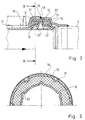
- FIGS. 2 and 3 a first design is used, as shown in FIGS. 2 and 3.
- a pipe part 2 can again be seen, to which a support part 12 connects and is firmly connected to the pipe part 2.
- the support part 12 between flanks 13 and 14 forms a chamber for two support pads 15 and 16.
- the chamber receiving the support pads is closed radially inward by the free end of an inner protective tube 17 which is connected to the bellows shaft 18 between the two support rings 15 and 16 protrudes.
- the end of the line element 18 in the form of an annular corrugated tube facing the support part 12 is welded to the support part 12 at 19 where the support part 12 has a circumferential seam along which it is joined after assembly.
- inner protective pipe 17 and Support part 12 is supported against each other by indirect mutual positive engagement in the circumferential direction.
- the support part 12 has radially inward and axially parallel indentations 20, 21, while on the other hand the inner protective tube 17 is provided with radially outward, axially parallel indentations 22, 23.
- the embossments 20, 21 are offset in relation to the embossments 22, 23 in the circumferential direction, so that the support pads 15, 16 do not experience too great a local weakening.
- the support pads 15, 16 have groove-shaped recesses which correspond to the impressions 20, 21 and the expressions 22, 23.
- FIGS. 4 and 5 show a tube part 1, a support part 25, an inner protective tube 26, a line element 27 with a bellows shaft 28 directed radially outwards, which goes between two support pads 29, 30.
- the support part 25 is composed of two parts 31, 32 which are connected to one another by a ring 33 which is welded to the parts 31, 32. This welding also simultaneously fixes the end of the line element 27 on the part 32.
- the ring 33 has a plurality of indentations 34 distributed over the circumference, which engage in groove-shaped, axially parallel recesses or cutouts 35 of the bellows shaft 28 and thus prevent the two tubular parts which are articulated from one another from rotating.
- FIG. 6 shows another variant in a partial representation.
- the support member 36 is provided on its circumferential weld 37, with which the end 38 of a line element is also gripped, on the inside with a ring 39, which is provided with projections 40 in the form of teeth or which are arranged around the circumference and project radially inwards the like is provided.
Landscapes
- Engineering & Computer Science (AREA)
- General Engineering & Computer Science (AREA)
- Mechanical Engineering (AREA)
- Chemical & Material Sciences (AREA)
- Combustion & Propulsion (AREA)
- Joints Allowing Movement (AREA)
Applications Claiming Priority (2)
| Application Number | Priority Date | Filing Date | Title |
|---|---|---|---|
| DE4219241A DE4219241A1 (de) | 1992-06-12 | 1992-06-12 | Gelenkige verbindung von rohrteilen, insbesondere bei abgasleitungen von kraftfahrzeugen |
| DE4219241 | 1992-06-12 |
Publications (2)
| Publication Number | Publication Date |
|---|---|
| EP0573764A1 true EP0573764A1 (fr) | 1993-12-15 |
| EP0573764B1 EP0573764B1 (fr) | 1995-09-13 |
Family
ID=6460863
Family Applications (1)
| Application Number | Title | Priority Date | Filing Date |
|---|---|---|---|
| EP93106728A Expired - Lifetime EP0573764B1 (fr) | 1992-06-12 | 1993-04-26 | Joint articulé d'éléments de tube, notamment dans des conduits d'échappement de véhicules automobiles |
Country Status (2)
| Country | Link |
|---|---|
| EP (1) | EP0573764B1 (fr) |
| DE (2) | DE4219241A1 (fr) |
Cited By (9)
| Publication number | Priority date | Publication date | Assignee | Title |
|---|---|---|---|---|
| GB2277969A (en) * | 1993-04-09 | 1994-11-16 | Iwk Regler Kompensatoren | Articulated coupling for internal combustion engine |
| US5957504A (en) * | 1997-04-10 | 1999-09-28 | Senior Engineering Investments Ag | Exhaust manifold attachment apparatus |
| US5984372A (en) * | 1997-04-10 | 1999-11-16 | Senior Engineering Investments Ag | Integrated flange-mesh ring assembly for decoupler apparatus |
| US6086110A (en) * | 1997-04-10 | 2000-07-11 | Senior Engineering Investments Ag | Vibration decoupling connector for exhaust systems |
| US6311736B2 (en) | 1998-05-28 | 2001-11-06 | Donaldson Company, Inc. | Flexible hose and method for manufacturing |
| US6464257B1 (en) | 1997-04-10 | 2002-10-15 | Senior Investments Ag | Vibration decoupler apparatus |
| EP1045118A3 (fr) * | 1999-04-16 | 2003-04-02 | Senior Investments AG | Dispositif de couplage flexible |
| US6568715B2 (en) | 2001-05-17 | 2003-05-27 | Senior Investments Ag | Vibration decoupling exhaust connector |
| EP1647754A3 (fr) * | 2004-10-15 | 2007-03-28 | Rasmussen GmbH | Raccordement de deux conduits et bague d'étanchéité pour le raccordement |
Families Citing this family (5)
| Publication number | Priority date | Publication date | Assignee | Title |
|---|---|---|---|---|
| DE4219241A1 (de) * | 1992-06-12 | 1992-10-22 | Witzenmann Metallschlauchfab | Gelenkige verbindung von rohrteilen, insbesondere bei abgasleitungen von kraftfahrzeugen |
| DE9301772U1 (de) * | 1993-02-09 | 1993-03-25 | IWK Regler und Kompensatoren GmbH, 76297 Stutensee | Gelenkige Verbindung von Rohrteilen |
| DE19630222C1 (de) * | 1996-07-26 | 1998-02-19 | Daimler Benz Ag | Vorrichtung zum Abkoppeln von Torsionsschwingungen |
| DE19758574A1 (de) * | 1997-08-11 | 1999-09-30 | Daimler Chrysler Ag | Vorrichtung zum Verbinden von zwei rohrförmigen Leitungsteilen in der Abgasanlage eines Kraftfahrzeuges |
| KR100281630B1 (ko) * | 1998-01-20 | 2001-02-15 | 김용호 | 자동차 배기관용 디커플러 |
Citations (2)
| Publication number | Priority date | Publication date | Assignee | Title |
|---|---|---|---|---|
| DE3610684A1 (de) * | 1986-03-29 | 1987-01-02 | Witzenmann Metallschlauchfab | Gelenkige verbindung von rohrteilen, insbesondere bei abgasleitungen von kraftfahrzeugen |
| DE4219241A1 (de) * | 1992-06-12 | 1992-10-22 | Witzenmann Metallschlauchfab | Gelenkige verbindung von rohrteilen, insbesondere bei abgasleitungen von kraftfahrzeugen |
Family Cites Families (1)
| Publication number | Priority date | Publication date | Assignee | Title |
|---|---|---|---|---|
| DE3524931A1 (de) * | 1985-07-12 | 1986-02-20 | Witzenmann GmbH, Metallschlauch-Fabrik Pforzheim, 7530 Pforzheim | Gelenkige verbindung von rohrteilen, insbesondere bei abgasleitungen von kraftfahrzeugen |
-
1992
- 1992-06-12 DE DE4219241A patent/DE4219241A1/de not_active Withdrawn
-
1993
- 1993-04-26 DE DE59300581T patent/DE59300581D1/de not_active Expired - Fee Related
- 1993-04-26 EP EP93106728A patent/EP0573764B1/fr not_active Expired - Lifetime
Patent Citations (2)
| Publication number | Priority date | Publication date | Assignee | Title |
|---|---|---|---|---|
| DE3610684A1 (de) * | 1986-03-29 | 1987-01-02 | Witzenmann Metallschlauchfab | Gelenkige verbindung von rohrteilen, insbesondere bei abgasleitungen von kraftfahrzeugen |
| DE4219241A1 (de) * | 1992-06-12 | 1992-10-22 | Witzenmann Metallschlauchfab | Gelenkige verbindung von rohrteilen, insbesondere bei abgasleitungen von kraftfahrzeugen |
Cited By (13)
| Publication number | Priority date | Publication date | Assignee | Title |
|---|---|---|---|---|
| GB2277969B (en) * | 1993-04-09 | 1996-01-24 | Iwk Regler Kompensatoren | Exhaust gas pipe particularly for motor vehicles |
| GB2277969A (en) * | 1993-04-09 | 1994-11-16 | Iwk Regler Kompensatoren | Articulated coupling for internal combustion engine |
| US5957504A (en) * | 1997-04-10 | 1999-09-28 | Senior Engineering Investments Ag | Exhaust manifold attachment apparatus |
| US5984372A (en) * | 1997-04-10 | 1999-11-16 | Senior Engineering Investments Ag | Integrated flange-mesh ring assembly for decoupler apparatus |
| US6086110A (en) * | 1997-04-10 | 2000-07-11 | Senior Engineering Investments Ag | Vibration decoupling connector for exhaust systems |
| US6167622B1 (en) | 1997-04-10 | 2001-01-02 | Senior Investments Ag | Exhaust manifold attachment apparatus and method for fabricating same |
| US6464257B1 (en) | 1997-04-10 | 2002-10-15 | Senior Investments Ag | Vibration decoupler apparatus |
| EP0921283A3 (fr) * | 1997-12-05 | 2003-03-26 | Senior Engineering Investments AG | Dispositif de découplage de vibrations |
| US6311736B2 (en) | 1998-05-28 | 2001-11-06 | Donaldson Company, Inc. | Flexible hose and method for manufacturing |
| EP1045118A3 (fr) * | 1999-04-16 | 2003-04-02 | Senior Investments AG | Dispositif de couplage flexible |
| US6568715B2 (en) | 2001-05-17 | 2003-05-27 | Senior Investments Ag | Vibration decoupling exhaust connector |
| EP1647754A3 (fr) * | 2004-10-15 | 2007-03-28 | Rasmussen GmbH | Raccordement de deux conduits et bague d'étanchéité pour le raccordement |
| US7393020B2 (en) | 2004-10-15 | 2008-07-01 | Norma Germany Gmbh | Connection of two pipes and sealing ring for the connection |
Also Published As
| Publication number | Publication date |
|---|---|
| EP0573764B1 (fr) | 1995-09-13 |
| DE59300581D1 (de) | 1995-10-19 |
| DE4219241A1 (de) | 1992-10-22 |
Similar Documents
| Publication | Publication Date | Title |
|---|---|---|
| EP0208128B1 (fr) | Connexion articulée d'éléments de tube, notamment dans des conduits d'échappement de véhicules automobiles | |
| DE69404406T2 (de) | Biegsame Verbindung für ein Autoauspuffrohr | |
| EP0573764B1 (fr) | Joint articulé d'éléments de tube, notamment dans des conduits d'échappement de véhicules automobiles | |
| DE4412132C2 (de) | Abdichtung für eine Gelenkkreuzbüchse | |
| EP0580963B1 (fr) | Conduite articulée | |
| DE3610684A1 (de) | Gelenkige verbindung von rohrteilen, insbesondere bei abgasleitungen von kraftfahrzeugen | |
| DE29907590U1 (de) | Abkoppelelement zur Abkopplung von Schwingungen | |
| EP0508145B1 (fr) | Conduit d'échappement isolé par une couche d'air | |
| DE29701625U1 (de) | Flexibles Leitungselement für Abgasleitungen | |
| EP1270987A2 (fr) | Support pour un agrégat en forme de manchon | |
| DE69504469T2 (de) | Verbesserungen in vibrationsdämpfenden hydraulischen Stützen | |
| EP0681097B1 (fr) | Elément de connexion flexible pour éléments tubulaires | |
| DE4307514C2 (de) | Verbinder für dünne Rohre | |
| DE29509434U1 (de) | Entkopplungselement für Schwingungen in Rohrleitungen | |
| DE2810942A1 (de) | Dichtungsanordnung | |
| EP0398086A1 (fr) | Raccordement pour deux tuyaux d'un conduit pour médium chaud | |
| DE102013106075B4 (de) | Vorrichtung zum schwingungsentkoppelten Verbinden zweier Einrichtungen einer Abgasanlage | |
| EP0575727A1 (fr) | Joint de tuyau | |
| DE69703856T2 (de) | Kupplung für zwei Metallrohre | |
| EP0295444B1 (fr) | Connexion de deux tuyaux d'une conduite pour fluides chauds | |
| DE102013210982A1 (de) | Dehnkörper zur Verbindung von zwei Rohrstücken insbesondere eines Abgaskanals eines Kraftfahrzeugs sowie Abgasturboladereinheit mit einem derartigen Dehnkörper | |
| EP0250901B1 (fr) | Dispositif pour désaccoupler les mouvements de torsion entre des éléments de tuyau | |
| DE19755563C1 (de) | Mittellager für eine Welle | |
| EP1531242B1 (fr) | Elément de découplage pour systèmes d'échappement | |
| EP1298403A2 (fr) | Dispositif de fixation d'un échangeur de chaleur pour gaz d'échappement |
Legal Events
| Date | Code | Title | Description |
|---|---|---|---|
| PUAI | Public reference made under article 153(3) epc to a published international application that has entered the european phase |
Free format text: ORIGINAL CODE: 0009012 |
|
| AK | Designated contracting states |
Kind code of ref document: A1 Designated state(s): DE FR GB IT |
|
| 17P | Request for examination filed |
Effective date: 19931125 |
|
| 17Q | First examination report despatched |
Effective date: 19950213 |
|
| GRAA | (expected) grant |
Free format text: ORIGINAL CODE: 0009210 |
|
| ITF | It: translation for a ep patent filed | ||
| AK | Designated contracting states |
Kind code of ref document: B1 Designated state(s): DE FR GB IT |
|
| GBT | Gb: translation of ep patent filed (gb section 77(6)(a)/1977) |
Effective date: 19950920 |
|
| REF | Corresponds to: |
Ref document number: 59300581 Country of ref document: DE Date of ref document: 19951019 |
|
| ET | Fr: translation filed | ||
| PGFP | Annual fee paid to national office [announced via postgrant information from national office to epo] |
Ref country code: FR Payment date: 19960415 Year of fee payment: 4 |
|
| PGFP | Annual fee paid to national office [announced via postgrant information from national office to epo] |
Ref country code: DE Payment date: 19960426 Year of fee payment: 4 |
|
| PLBE | No opposition filed within time limit |
Free format text: ORIGINAL CODE: 0009261 |
|
| 26N | No opposition filed | ||
| PG25 | Lapsed in a contracting state [announced via postgrant information from national office to epo] |
Ref country code: GB Effective date: 19970426 |
|
| GBPC | Gb: european patent ceased through non-payment of renewal fee |
Effective date: 19970426 |
|
| PG25 | Lapsed in a contracting state [announced via postgrant information from national office to epo] |
Ref country code: FR Free format text: LAPSE BECAUSE OF NON-PAYMENT OF DUE FEES Effective date: 19971231 |
|
| PG25 | Lapsed in a contracting state [announced via postgrant information from national office to epo] |
Ref country code: DE Free format text: LAPSE BECAUSE OF NON-PAYMENT OF DUE FEES Effective date: 19980101 |
|
| REG | Reference to a national code |
Ref country code: FR Ref legal event code: ST |
|
| PG25 | Lapsed in a contracting state [announced via postgrant information from national office to epo] |
Ref country code: IT Free format text: LAPSE BECAUSE OF NON-PAYMENT OF DUE FEES;WARNING: LAPSES OF ITALIAN PATENTS WITH EFFECTIVE DATE BEFORE 2007 MAY HAVE OCCURRED AT ANY TIME BEFORE 2007. THE CORRECT EFFECTIVE DATE MAY BE DIFFERENT FROM THE ONE RECORDED. Effective date: 20050426 |