EP0573779A1 - Freilaufsicherung für metallurgische Gefässe mit Bodenverschluss - Google Patents
Freilaufsicherung für metallurgische Gefässe mit Bodenverschluss Download PDFInfo
- Publication number
- EP0573779A1 EP0573779A1 EP93107293A EP93107293A EP0573779A1 EP 0573779 A1 EP0573779 A1 EP 0573779A1 EP 93107293 A EP93107293 A EP 93107293A EP 93107293 A EP93107293 A EP 93107293A EP 0573779 A1 EP0573779 A1 EP 0573779A1
- Authority
- EP
- European Patent Office
- Prior art keywords
- bottom closure
- base body
- pouring channel
- plugging means
- metallurgical vessels
- Prior art date
- Legal status (The legal status is an assumption and is not a legal conclusion. Google has not performed a legal analysis and makes no representation as to the accuracy of the status listed.)
- Granted
Links
Images
Classifications
-
- C—CHEMISTRY; METALLURGY
- C21—METALLURGY OF IRON
- C21C—PROCESSING OF PIG-IRON, e.g. REFINING, MANUFACTURE OF WROUGHT-IRON OR STEEL; TREATMENT IN MOLTEN STATE OF FERROUS ALLOYS
- C21C5/00—Manufacture of carbon-steel, e.g. plain mild steel, medium carbon steel or cast steel or stainless steel
- C21C5/28—Manufacture of steel in the converter
- C21C5/42—Constructional features of converters
- C21C5/46—Details or accessories
- C21C5/4653—Tapholes; Opening or plugging thereof
-
- B—PERFORMING OPERATIONS; TRANSPORTING
- B22—CASTING; POWDER METALLURGY
- B22D—CASTING OF METALS; CASTING OF OTHER SUBSTANCES BY THE SAME PROCESSES OR DEVICES
- B22D41/00—Casting melt-holding vessels, e.g. ladles, tundishes, cups or the like
- B22D41/14—Closures
- B22D41/44—Consumable closure means, i.e. closure means being used only once
- B22D41/46—Refractory plugging masses
Definitions
- the invention relates to a freewheel device for metallurgical vessels with a bottom closure for the safe release of the pouring channel after opening the bottom closure.
- the object of the invention is to find a freewheel lock for metallurgical vessels with a bottom closure, which can be used regardless of the state of wear of a pouring channel, enables safe filling of the pouring channel and is characterized by simple handling and economically advantageous production.
- the object is achieved by a freewheel lock, which consists of a shell-shaped to tubular base body which adapts to a changing wear channel cross-section and has bending folds on its two end faces which are angled by approximately 90 ° to the inside of the lateral surface.
- the base body which is preferably made of sheet steel material, is dimensioned such that its outer surface is at least equal to or greater than half the inner surface of a pouring channel to be filled with heat-resistant pusher sand or other filling material and expediently protrudes into the interior of a casting vessel to accommodate a sufficient amount of filling material.
- the freewheel device according to the invention consists, in addition to the shell-shaped to tubular base body, of a flexible hose filled with the required amount of pusher sand.
- the flexible hose is expediently made of material which melts or burns after a short time under the influence of the temperature prevailing in the pouring channel. It is inserted into the base body and thus introduced into the pouring channel with the ladle lying flat and the bottom closure open.
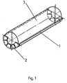
- the freewheel lock consists of a base body 1, which has a half-shell-shaped cross section and is made of sheet metal material.
- the end faces of the base body 1 are provided with bending folds 2, which are angled at an angle of 90 ° to the inner lateral surface of the base body 1.
- sheet material sheet steel is preferably used in order to ensure a sufficient service life of the base body 1 until the casting vessel is erected.
- the length of the base body 1 is such that it protrudes beyond the pouring channel of a casting vessel with a bottom closure into the interior of the vessel, thereby ensuring a sufficient possibility of receiving a necessary amount of pusher sand.
- the required amount of pusher sand is contained in a flexible hose 3, which consists of an easily flammable or heat-resistant material (plastic film).
- the film tube 3 with the metered amount of pusher sand is inserted into the half-shell-shaped base body 1 and, in this position, inserted into the pouring channel with the casting vessel lying down and the bottom closure open. Immediately afterwards, the bottom closure is closed and the pouring vessel is erected, the sliding sand being released by burning the film tube 3 completely filling the pouring channel.
- the lateral surface can be pre-bent beyond the half-shell-shaped cross section. All that is required to insert the hose 3 is a brief bending of the base body 1.
Landscapes
- Engineering & Computer Science (AREA)
- Chemical & Material Sciences (AREA)
- Manufacturing & Machinery (AREA)
- Materials Engineering (AREA)
- Metallurgy (AREA)
- Organic Chemistry (AREA)
- Mechanical Engineering (AREA)
- Casting Support Devices, Ladles, And Melt Control Thereby (AREA)
- Packages (AREA)
- Furnace Charging Or Discharging (AREA)
- Vertical, Hearth, Or Arc Furnaces (AREA)
Abstract
Description
- Die Erfindung betrifft eine Freilaufsicherung für metallurgische Gefäße mit Bodenverschluß zur sicheren Freigabe des Gießkanals nach dem Öffnen des Bodenverschlusses.
- Zur Verhinderung der Erstarrung von Metallschmelze in einem Gießkanal eines metallurgischen Gefäßes mit Bodenverschluß während ihrer Verweilzeit in dem Gefäß bis zum Öffnen des Bodenverschlusses ist es bekannt, in den Gießkanal ein hitzebeständiges Füllmaterial einzubringen. Als Füllmaterial wird dabei in der Regel Schiebersand verwendet, welcher bei Öffnung des Bodenverschlusses zuerst aus dem Gießkanal fließt und damit den Ausfluß für die nachströmende Metallschmelze frei gibt. Das Füllmaterial wird dabei entweder von oben bei stehendem Gefäß oder von unten bei liegendem Gefäß und geöffneten Bodenverschluß dem Gießkanal zugeführt. Zum Einbringen einer Schiebersandmenge durch den Bodenverschluß ist es bekannt, geschlossene Hülsenkörper zu verwenden. Derartige Lösungen sind z. B. in der DD-PS 117379 und DD-PS 280270 veröffentlicht. Die Herstellung derartiger Hülsenkörper ist in der Regel aufwendig und erfordert eine gewisse Sorgfalt, um eine hohe Öffnungsrate bei ihrem Einsatz zu erzielen.
- Aufgabe der Erfindung ist es, eine Freilaufsicherung für metallurgische Gefäße mit Bodenverschluß zu finden, welche unabhängig vom Verschleißzustand eines Gießkanals einsetzbar ist, ein sicheres Verfüllen des Gießkanals ermöglicht und sich durch eine einfache Handhabung und wirtschaftlich günstige Fertigung auszeichnet.
Erfindungsgemäß wird die Aufgabe durch eine Freilaufsicherung gelöst, welche aus einem schalenförmig bis rohrförmig ausgebildeten Grundkörper besteht, der sich einem durch Verschleiß verändernden Gießkanalquerschnitt anpaßt und an seinen beiden Stirnseiten Biegefalze aufweist, die um ca. 90 ° zur Innenseite der Mantelfläche abgewinkelt sind. - Der vorzugsweise aus Stahlblechmaterial gefertigte Grundkörper ist so bemessen, daß seine Mantelfläche mindestens gleich oder größer der halben Innenfläche eines mit einem hitzbeständigen Schiebersand oder anderem Füllmaterial zu verfüllenden Gießkanals ist und zweckmäßigerweise zur Aufnahme einer ausreichenden Menge an Füllmaterial in das Innere eines Gießgefäßes hineinragt.
Die erfindungsgemäße Freilaufsicherung besteht neben dem schalenförmig bis rohrförmig ausgebildeten Grundkörper aus einem mit der erforderlichen Menge Schiebersand gefüllten flexiblen Schlauch. Der flexible Schlauch ist zweckmäßigerweise aus Material gefertigt, welches unter der Einwirkung der im Gießkanal vorherrschenden Temperatur nach kurzer Zeit aufschmilzt bzw. verbrennt. Er wird in den Grundkörper eingebracht und so bei liegender Gießpfanne und geöffneten Bodenverschluß in den Gießkanal eingeführt. Unmittelbar danach erfolgt , nachdem der Bodenverschluß geschlossen wurde, das Aufrichten der Gießpfanne, wobei der Schiebersand den Gießkanal voll ausfüllt. Aufgrund der einfachen Gestaltung des schalenförmigen bis rohrförmigen Grundkörpers und der dosierten Zugabe einer erforderlichen Menge Schiebersand mittels eines flexiblen Schlauches wurde eine äußerst praktische Lösung für das Verfüllen eines Ausgußkanals eines metallurgischen Gefäßes mit Bodenverschluß gefunden. - Die erfindungsgemäße Lösung soll nachfolgend an einem Ausführungsbeispiel näher erläutert werden. In der dazugehörenden Zeichnung zeigt
- Fig. 1 eine Perspektivansicht der Freilaufsicherung.
- Die Freilaufsicherung besteht aus einem Grundkörper 1, der einen halbschalenförmigen Querschnitt aufweist und aus Blechmaterial gefertigt ist. Die Stirnseiten des Grundkörpers 1 sind mit Biegefalzen 2 versehen, welche in einem Winkel von 90 ° zur inneren Mantelfläche des Grundkörpers 1 abgewinkelt sind. Als Blechmaterial wird vorzugsweise Stahlblech verwendet, um eine ausreichende Standzeit des Grundkörpers 1 bis zum Aufrichten des Gießgefäßes zu gewährleisten. Der Grundkörper 1 ist in seiner Länge so bemessen, daß er über den Ausgußkanal eines Gießgefäßes mit Bodenverschluß hinaus in das Innere des Gefäßes hineinragt, wodurch eine ausreichende Aufnahmemöglichkeit für eine notwendige Menge Schiebersand gewährleistet ist. Die erforderliche Schiebersandmenge ist in einem flexiblen Schlauch 3 enthalten, der aus einem leicht brennbaren bzw. hitzeunbeständigen Material (Kunststoffolie) besteht. In den halbschalenförmigen Grundkörper 1 wird der Folienschlauch 3 mit der dosierten Menge Schiebersand eingelegt und in dieser Lage bei liegendem Gießgefäß und geöffnetem Bodenverschluß in den Gießkanal eingeführt. Unmittelbar danach erfolgt das Verschließen des Bodenverschlusses und das Aufrichten des Gießgefäßes, wobei der durch Verbrennen des Folienschlauches 3 freiwerdende Schiebersand den Gießkanal vollständig ausfüllt.
Bei einer weiteren Ausführungsform der erfindungsgemäßen Freilaufsicherung kann die Mantelfläche über den halbschalenförmigen Querschnitt hinaus vorgebogen sein. Zum Einlegen des Schlauches 3 bedarf es dabei lediglich eines kurzzeitigen Aufbiegens des Grundkörpers 1.
Claims (2)
- Freilaufsicherung für metallurgische Gefäße mit Bodenverschluß, dadurch gekennzeichnet, daß die Freilaufsicherung aus einem schalenförmig bis rohrförmig ausgebildeten Grundkörper (1) besteht, der an seinen beiden Stirnseiten um ca. 90 Grad zur Innenseite der Mantelfläche abgewinkelte Biegefalze (2) aufweist und in diesem Grundkörper (1) ein mit der erforderlichen Schiebersandmenge oder anderem geeigneten Füllmaterial gefüllter Schlauch (3) eingelagert ist.
- Freilaufsicherung nach Anspruch 1, dadurch gekennzeichnet, daß die Mantelfläche des Grundkörpers (1) mindestens gleich oder größer der halben Innenfläche eines Gießkanals ist.
Applications Claiming Priority (2)
| Application Number | Priority Date | Filing Date | Title |
|---|---|---|---|
| DE4218512 | 1992-06-02 | ||
| DE4218512A DE4218512C2 (de) | 1992-06-02 | 1992-06-02 | Freilaufsicherung für metallurgische Gefäße mit Bodenverschluß |
Publications (2)
| Publication Number | Publication Date |
|---|---|
| EP0573779A1 true EP0573779A1 (de) | 1993-12-15 |
| EP0573779B1 EP0573779B1 (de) | 1995-10-11 |
Family
ID=6460430
Family Applications (1)
| Application Number | Title | Priority Date | Filing Date |
|---|---|---|---|
| EP93107293A Expired - Lifetime EP0573779B1 (de) | 1992-06-02 | 1993-05-05 | Freilaufsicherung für metallurgische Gefässe mit Bodenverschluss |
Country Status (6)
| Country | Link |
|---|---|
| EP (1) | EP0573779B1 (de) |
| AT (1) | ATE128892T1 (de) |
| DE (2) | DE4218512C2 (de) |
| ES (1) | ES2081656T3 (de) |
| RU (1) | RU2086353C1 (de) |
| UA (1) | UA26259C2 (de) |
Families Citing this family (1)
| Publication number | Priority date | Publication date | Assignee | Title |
|---|---|---|---|---|
| CN113523261A (zh) * | 2020-04-21 | 2021-10-22 | 宝山钢铁股份有限公司 | 一种钢包自开用引流砂及其钢包自开方法 |
Citations (3)
| Publication number | Priority date | Publication date | Assignee | Title |
|---|---|---|---|---|
| WO1980001659A1 (en) * | 1979-02-17 | 1980-08-21 | Foseco Int | Metallurgical pouring vessels |
| US4795066A (en) * | 1982-09-23 | 1989-01-03 | Kaiser Steel Corporation | Ladle nozzle insert |
| DE9106699U1 (de) * | 1990-08-24 | 1991-08-29 | EKO Stahl AG, O-1220 Eisenhüttenstadt | Freilaufsicherung für metallurgische Gefäße mit Bodenverschluß |
Family Cites Families (2)
| Publication number | Priority date | Publication date | Assignee | Title |
|---|---|---|---|---|
| SE7412784L (de) * | 1973-10-12 | 1975-04-14 | Uss Eng & Consult | |
| DD280270A1 (de) * | 1989-03-08 | 1990-07-04 | Veb Bandstahlkombinat "Hermann Matern",Dd | Schieberhuelse fuer metallurgische gefaesse |
-
1992
- 1992-06-02 DE DE4218512A patent/DE4218512C2/de not_active Expired - Fee Related
-
1993
- 1993-05-05 AT AT93107293T patent/ATE128892T1/de not_active IP Right Cessation
- 1993-05-05 ES ES93107293T patent/ES2081656T3/es not_active Expired - Lifetime
- 1993-05-05 DE DE59300738T patent/DE59300738D1/de not_active Expired - Fee Related
- 1993-05-05 EP EP93107293A patent/EP0573779B1/de not_active Expired - Lifetime
- 1993-06-01 RU RU9393028442A patent/RU2086353C1/ru not_active IP Right Cessation
- 1993-06-17 UA UA93002959A patent/UA26259C2/uk unknown
Patent Citations (3)
| Publication number | Priority date | Publication date | Assignee | Title |
|---|---|---|---|---|
| WO1980001659A1 (en) * | 1979-02-17 | 1980-08-21 | Foseco Int | Metallurgical pouring vessels |
| US4795066A (en) * | 1982-09-23 | 1989-01-03 | Kaiser Steel Corporation | Ladle nozzle insert |
| DE9106699U1 (de) * | 1990-08-24 | 1991-08-29 | EKO Stahl AG, O-1220 Eisenhüttenstadt | Freilaufsicherung für metallurgische Gefäße mit Bodenverschluß |
Also Published As
| Publication number | Publication date |
|---|---|
| EP0573779B1 (de) | 1995-10-11 |
| DE4218512A1 (de) | 1993-12-09 |
| DE59300738D1 (de) | 1995-11-16 |
| UA26259C2 (uk) | 1999-07-19 |
| DE4218512C2 (de) | 1994-03-24 |
| ATE128892T1 (de) | 1995-10-15 |
| RU2086353C1 (ru) | 1997-08-10 |
| ES2081656T3 (es) | 1996-03-16 |
Similar Documents
| Publication | Publication Date | Title |
|---|---|---|
| DE2709727C3 (de) | Einrichtung zum Auswechseln von Gießrohren an Gießgefäßen beim Stranggießen | |
| DE1608094C (de) | ||
| DE1608094B1 (de) | Anlage zur vollkontinuierlichen Versorgung einer Stranggiessanlage mit Metallschmelze | |
| DE1458093B2 (de) | Gießvorrichtung, insbesondere für Aluminium-Kokillenguß | |
| DE2933989A1 (de) | Vorrichtung zum ablassen von in einem zwischenbehaelter verbliebener metallschmelze und schlacke | |
| DE2746265A1 (de) | Schieberventil fuer ein giessgefaess | |
| DE1773164A1 (de) | Vorrichtung zur Entnahme von Proben aus einem Bad | |
| EP0573779B1 (de) | Freilaufsicherung für metallurgische Gefässe mit Bodenverschluss | |
| DD301654A5 (de) | Freilaufsicherung fuer metallurgische gefaesse mit bodenverschluss | |
| DE2317663A1 (de) | Vorrichtung zur steuerung des ausflusses der metallschmelze aus einem schmelzgutbehaelter | |
| DE3151533C2 (de) | Verlängerte Ausgußdüse für Zwischenbehälter | |
| DE3605536C2 (de) | ||
| EP0392168B1 (de) | Schliess- und/oder Regelorgan für ein metallurgisches Gefäss | |
| DE1949995A1 (de) | Zwischenbehaelter (Tundish) fuer Stranggiessanlagen | |
| DE3509571C1 (de) | Kammerwand | |
| DD258952A5 (de) | Verfahren und vorrichtung zum eindruecken von substanzen in hochtemperatur-fluessigkeiten | |
| DE2442109C2 (de) | Verfahren und Vorrichtung zum Bandagieren von Gegenständen, vorzugsweise von feuerfest bewehrten Ausgußstutzen von Gießpfannen | |
| DE2217726C3 (de) | Vorrichtung zum Verstopfen des Abstich loches von rotierenden Konvertern | |
| DE2755738A1 (de) | Vorrichtung zur lanzenfuehrung | |
| EP1160030B1 (de) | Vergiesseinrichtung für flüssiges Metall | |
| EP0000466A1 (de) | Verfahren zum Einbringen von körnigen Stoffen in eine Metallschmelze und Vorrichtung zur Durchführung des Verfahrens | |
| DE2929613A1 (de) | Einrichtung an einer stranggiessanlage | |
| AT407056B (de) | Verfahren zum verschliessen und öffnen eines stichloches eines kippbaren metallurgischen gefässes | |
| DE672416C (de) | Vorrichtung zum Giessen langgestreckter, voller Metallteile | |
| DE2816204C2 (de) | Transportbehälter fur schmelzflüssiges Metall |
Legal Events
| Date | Code | Title | Description |
|---|---|---|---|
| PUAI | Public reference made under article 153(3) epc to a published international application that has entered the european phase |
Free format text: ORIGINAL CODE: 0009012 |
|
| AK | Designated contracting states |
Kind code of ref document: A1 Designated state(s): AT BE DE ES FR GB IT LU NL SE |
|
| 17P | Request for examination filed |
Effective date: 19931209 |
|
| 17Q | First examination report despatched |
Effective date: 19940114 |
|
| RAP1 | Party data changed (applicant data changed or rights of an application transferred) |
Owner name: EKO STAHL GMBH |
|
| GRAA | (expected) grant |
Free format text: ORIGINAL CODE: 0009210 |
|
| ITF | It: translation for a ep patent filed | ||
| AK | Designated contracting states |
Kind code of ref document: B1 Designated state(s): AT BE DE ES FR GB IT LU NL SE |
|
| REF | Corresponds to: |
Ref document number: 128892 Country of ref document: AT Date of ref document: 19951015 Kind code of ref document: T |
|
| REF | Corresponds to: |
Ref document number: 59300738 Country of ref document: DE Date of ref document: 19951116 |
|
| GBT | Gb: translation of ep patent filed (gb section 77(6)(a)/1977) |
Effective date: 19951220 |
|
| ET | Fr: translation filed | ||
| REG | Reference to a national code |
Ref country code: ES Ref legal event code: FG2A Ref document number: 2081656 Country of ref document: ES Kind code of ref document: T3 |
|
| PGFP | Annual fee paid to national office [announced via postgrant information from national office to epo] |
Ref country code: DE Payment date: 19960621 Year of fee payment: 4 |
|
| PLBE | No opposition filed within time limit |
Free format text: ORIGINAL CODE: 0009261 |
|
| 26N | No opposition filed | ||
| PG25 | Lapsed in a contracting state [announced via postgrant information from national office to epo] |
Ref country code: DE Free format text: LAPSE BECAUSE OF NON-PAYMENT OF DUE FEES Effective date: 19980203 |
|
| PGFP | Annual fee paid to national office [announced via postgrant information from national office to epo] |
Ref country code: SE Payment date: 19990507 Year of fee payment: 7 Ref country code: ES Payment date: 19990507 Year of fee payment: 7 |
|
| PG25 | Lapsed in a contracting state [announced via postgrant information from national office to epo] |
Ref country code: SE Free format text: LAPSE BECAUSE OF NON-PAYMENT OF DUE FEES Effective date: 20000506 Ref country code: ES Free format text: THE PATENT HAS BEEN ANNULLED BY A DECISION OF A NATIONAL AUTHORITY Effective date: 20000506 |
|
| EUG | Se: european patent has lapsed |
Ref document number: 93107293.8 |
|
| PGFP | Annual fee paid to national office [announced via postgrant information from national office to epo] |
Ref country code: GB Payment date: 20010514 Year of fee payment: 9 |
|
| PGFP | Annual fee paid to national office [announced via postgrant information from national office to epo] |
Ref country code: BE Payment date: 20010518 Year of fee payment: 9 |
|
| PGFP | Annual fee paid to national office [announced via postgrant information from national office to epo] |
Ref country code: FR Payment date: 20010529 Year of fee payment: 9 |
|
| PGFP | Annual fee paid to national office [announced via postgrant information from national office to epo] |
Ref country code: AT Payment date: 20010530 Year of fee payment: 9 |
|
| PGFP | Annual fee paid to national office [announced via postgrant information from national office to epo] |
Ref country code: NL Payment date: 20010531 Year of fee payment: 9 Ref country code: LU Payment date: 20010531 Year of fee payment: 9 |
|
| REG | Reference to a national code |
Ref country code: GB Ref legal event code: IF02 |
|
| REG | Reference to a national code |
Ref country code: ES Ref legal event code: FD2A Effective date: 20020204 |
|
| PG25 | Lapsed in a contracting state [announced via postgrant information from national office to epo] |
Ref country code: LU Free format text: LAPSE BECAUSE OF NON-PAYMENT OF DUE FEES Effective date: 20020505 Ref country code: GB Free format text: LAPSE BECAUSE OF NON-PAYMENT OF DUE FEES Effective date: 20020505 Ref country code: AT Free format text: LAPSE BECAUSE OF NON-PAYMENT OF DUE FEES Effective date: 20020505 |
|
| PG25 | Lapsed in a contracting state [announced via postgrant information from national office to epo] |
Ref country code: BE Free format text: LAPSE BECAUSE OF NON-PAYMENT OF DUE FEES Effective date: 20020531 |
|
| PG25 | Lapsed in a contracting state [announced via postgrant information from national office to epo] |
Ref country code: NL Free format text: LAPSE BECAUSE OF NON-PAYMENT OF DUE FEES Effective date: 20021201 |
|
| GBPC | Gb: european patent ceased through non-payment of renewal fee |
Effective date: 20020505 |
|
| PG25 | Lapsed in a contracting state [announced via postgrant information from national office to epo] |
Ref country code: FR Free format text: LAPSE BECAUSE OF NON-PAYMENT OF DUE FEES Effective date: 20030131 |
|
| NLV4 | Nl: lapsed or anulled due to non-payment of the annual fee |
Effective date: 20021201 |
|
| REG | Reference to a national code |
Ref country code: FR Ref legal event code: ST |
|
| PG25 | Lapsed in a contracting state [announced via postgrant information from national office to epo] |
Ref country code: IT Free format text: LAPSE BECAUSE OF NON-PAYMENT OF DUE FEES;WARNING: LAPSES OF ITALIAN PATENTS WITH EFFECTIVE DATE BEFORE 2007 MAY HAVE OCCURRED AT ANY TIME BEFORE 2007. THE CORRECT EFFECTIVE DATE MAY BE DIFFERENT FROM THE ONE RECORDED. Effective date: 20050505 |